Loop Protection for Spanning-Tree Protocols
Understanding Loop Protection for Spanning-Tree Instance Interfaces
Loop protection increases the efficiency of STP, RSTP, and MSTP by preventing ports from moving into a forwarding state that would result in a loop opening up in the network. Spanning-tree protocol loop protection enhances the normal checks that spanning-tree protocols perform on interfaces. Loop protection performs a specified action when BPDUs are not received on a nondesignated port interface. You can choose to block the interface or issue an alarm when bridge protocol data units (BPDUs) are not received on the port.
- How Does Loop Protection Work?
- Benefits of Loop Protection on STP Protocols
- What Action Causes a Loop?
- What Can Loop Protection Do When BPDUs Don’t Arrive?
- When Should I Use Loop Protection?
- What Happens if I Do Not Use Loop Protection?
How Does Loop Protection Work?
A loop-free network in spanning-tree topologies is supported through the exchange of a special type of frame called bridge protocol data unit (BPDU). Peer STP applications running on the switch interfaces use BPDUs to communicate. Ultimately, the exchange of BPDUs determines which interfaces block traffic (preventing loops) and which interfaces become root ports and forward traffic.
However, a blocking interface can transition to the forwarding state in error if the interface stops receiving BPDUs from its designated port on the segment. Such a transition error can occur when there is a hardware error on the switch or software configuration error between the switch and its neighbor.
When loop protection is enabled, the spanning-tree topology detects root ports and blocked ports and makes sure both keep receiving BPDUs. If a loop-protection-enabled interface stops receiving BPDUs from its designated port, it reacts as it would react to a problem with the physical connection on this interface. It does not transition the interface to a forwarding state, but instead transitions it to a loop-inconsistent state. The interface recovers and then it transitions back to the spanning-tree blocking state as soon as it receives a BPDU.
Benefits of Loop Protection on STP Protocols
By default, a spanning-tree protocol interface that stops receiving bridge protocol data unit (BPDU) data frames will transition to the designated port (forwarding) state, creating a potential loop.
What Action Causes a Loop?
The spanning-tree protocol family is responsible for breaking loops in a network of bridges with redundant links. However, hardware failures can create forwarding loops (STP loops) and cause major network outages. Spanning-tree protocols break loops by blocking ports (interfaces). However, errors occur when a blocked port transitions erroneously to a forwarding state.
Ideally, a spanning-tree protocol bridge port remains blocked as long as a superior alternate path to the root bridge exists for a connected LAN segment. This designated port is determined by receiving superior BPDUs from a peer on that port. When other ports no longer receive BPDUs, the spanning-tree protocol considers the topology to be loop free. However, if a blocked or alternate port moves into a forwarding state, this creates a loop.
What Can Loop Protection Do When BPDUs Don’t Arrive?
To prevent a spanning-tree instance interface from interpreting a lack of received BPDUs as a “false positive” condition for assuming the designated port role, you can configure one of the following loop protection options:
Configure the router to raise an alarm condition if the spanning-tree instance interface has not received BPDUs during the timeout interval.
Configure the router to block the spanning-tree instance interface if the interface has not received BPDUs during the timeout interval.
Spanning-tree instance interface loop protection is enabled for all spanning-tree instances on the interface, but blocks or alarms only those instances that stop receiving BPDUs.
When Should I Use Loop Protection?
You can configure spanning-tree protocol loop protection to improve the stability of Layer 2 networks. We recommend you configure loop protection only on non-designated interfaces such as the root or alternate interfaces. Otherwise, if you configure loop protection on both sides of a designated link, then certain STP configuration events (such as setting the root bridge priority to an inferior value in a topology with many loops) can cause both interfaces to transition to blocking mode.
We recommend that you enable loop protection on all switch interfaces that have a chance of becoming root or alternate ports. Loop protection is most effective when enabled in the entire switched network. When you enable loop protection, you must configure at least one action (log, block, or both).
An interface can be configured for either loop protection or root protection, but not for both.
What Happens if I Do Not Use Loop Protection?
By default (that is, without spanning-tree protocol loop protection configured), an interface that stops receiving BPDUs will assume the designated port role and possibly result in a spanning-tree protocol loop.
Eliminating Bridge Loops in Ethernet LANs with Spanning Tree Protocol
The Spanning Tree Protocol (STP) is a network protocol that is used to eliminate bridge loops in Ethernet LANs. STP prevents network loops and associated network outage by blocking redundant links or paths. The redundant paths can be used to keep the network operational if the primary link fails.
The sections describe bridge loops and how STP helps eliminate them.
Understanding Bridge Loops
To understand bridge loops, consider a scenario in which four switches (or bridges) are connected to four different subsections (Subsection i, ii, iii, and iv) where each subsection is a collection of network nodes (see Figure 1). For simplicity, Subsection i and Subsection ii are combined to form Section 1. Similarly, Subsection iii and Subsection iv are combined to form Section 2.
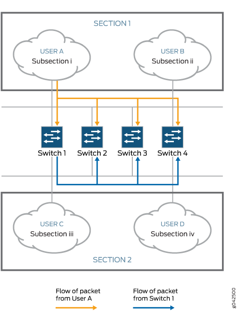
When the switches are powered on, the bridge tables are empty. If User A in Subsection i tries to send a single packet Packet 1 to User D in Subsection iv, all the switches, which are in listening mode, receive the packet. The switches make an entry in their respective bridging tables, as shown in the following table:
|
Bridge 1 ID | Port Facing Direction |
Bridge 2 ID | Port Facing Direction |
Bridge 3 ID | Port Facing Direction |
Bridge 4 ID | Port Facing Direction |
|---|---|---|---|
|
Packet 1 | Section 1 |
Packet 1 | Section 1 |
Packet 1 | Section 1 |
Packet 1 | Section 1 |
At this point, the switches do not know where Subsection iv is, and the packet is forwarded to all the ports except the source port (which results in flooding of the packet). In this example, after Subsection 1 sends the packet, the switches receive the packet on the ports facing Section 1. As a result, they start forwarding the packet through the ports facing Section 2. Which switch gets the first chance to send out the packet depends on the network configuration. In this example, suppose Switch 1 transmits the packet first. Because it received the packet from Section 1, it floods the packet toward Section 2. Similarly, Switches 2, 3, and 4, which are also in listening mode, receive the same packet from Switch 1 (originally sent from Section 1) on the ports facing Section 2. They readily update their bridging tables with incorrect information, as shown in the following table:
|
Bridge 1 ID | Port Facing Direction |
Bridge 2 ID | Port Facing Direction |
Bridge 3 ID | Port Facing Direction |
Bridge 4 ID | Port Facing Direction |
|---|---|---|---|
|
Packet 1 | Section 1 |
Packet 1 | Section 2 |
Packet 1 | Section 2 |
Packet 1 | Section 2 |
Thus, a loop is created as the same packet is received both from Section 1 and Section 2. As illustrated in Figure 1, Switch 1 has information that the packet came from Subsection i in Section 1, whereas all other switches have incorrect information that the same packet came from Section 2.
The entire process is repeated when Switch 2 gets the chance to transmit the original packet. Switch 2 receives the original packet from Section 1 and transmits the same packet to Section 2. Eventually, Switch 1, which still has no idea where Subsection iv is, updates its bridging table, as shown in the following table:
|
Bridge 1 ID | Port Facing Direction |
Bridge 2 ID | Port Facing Direction |
Bridge 3 ID | Port Facing Direction |
Bridge 4 ID | Port Facing Direction |
|---|---|---|---|
|
Packet 1 | Section 2 |
Packet 1 | Section 2 |
Packet 1 | Section 2 |
Packet 1 | Section 2 |
In complex networks, this process can quickly lead to huge packet transmission cycles as the same packet is sent repeatedly.
How STP Helps Eliminate Loops
Spanning Tree Protocol helps eliminate loops in a network by turning off additional routes that can create a loop. The blocked routes are enabled automatically if the primary path gets deactivated.
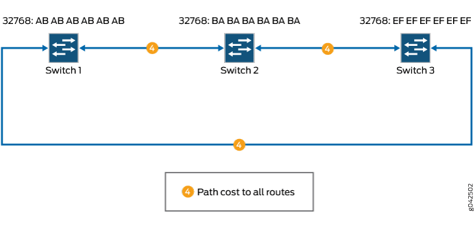
To understand the steps followed by STP in eliminating bridge loops, consider the following example where three switches are connected to form a simple network (see Figure 2). To maintain redundancy, more than one path exists between each device. The switches communicate with each other by using Bridge Protocol Data Units (BPDUs) sent every 2 seconds.
BPDUs are frames that consist of bridge ID, the bridge port where it originates, the priority of the bridge port, cost of the path and so on. BPDUs are sent as multicast MAC address 01:80:c2:00:00:00. BPDUs can be of three types: configuration BPDUs, topology change notification (TCN) BPDUs, and topology change acknowledgment (TCA) BPDUs.
To eliminate network loops, STP performs the following steps in this sample network:
-
Elects a root bridge (or switch). To elect a root switch, STP uses the bridge ID. The bridge ID is 8 bytes in length and consists of two parts. The first part is 2 bytes of information known as bridge priority. The default bridge priority is 32,768. In this example, the default value is used for all the switches. The remaining 6 bytes consist of the MAC address of the switch. In this example, Switch1 is elected as the root switch because it has the lowest MAC address.
-
Elects the root ports. Typically, root ports use the least-cost paths from one switch to the other. In this example, assume that all paths have similar costs. Therefore, the root port for Switch 2 is the port that receives packets through the direct path from Switch 1 (cost 4), because the other path is through Switch 3 (cost 4 + 4) as shown in Figure 3. Similarly, for Switch 3, the root port is the one that uses the direct path from Switch 1.
Figure 3: Electing Root Ports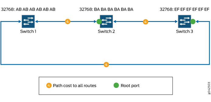
-
Selects the designated ports. Designated ports are the only ports that can receive and forward frames on switches other than the root switch. They are generally the ports that use the least-cost paths. In Figure 4, the designated ports are marked.
Figure 4: Selecting Designated Ports and Blocking Redundant Paths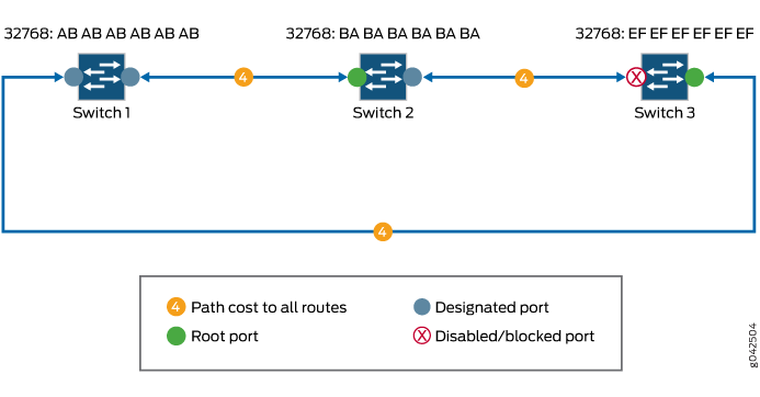
Because there is more than one path involved in the network and the root ports and designated ports are identified, STP can block the path between Switch 2 and Switch 3 temporarily, eliminating any Layer 2 loops.
Types of Spanning-Tree Protocols Supported
In a Layer 2 environment, you can configure various spanning-tree protocol versions to create a loop-free topology in Layer 2 networks.
A spanning-tree protocol is a Layer 2 control protocol (L2CP) that calculates the best path through a switched network containing redundant paths. A spanning-tree protocol uses bridge protocol data unit (BPDU) data frames to exchange information with other switches. A spanning-tree protocol uses the information provided by the BPDUs to elect a root bridge, identify root ports for each switch, identify designated ports for each physical LAN segment, and prune specific redundant links to create a loop-free tree topology. The resulting tree topology provides a single active Layer 2 data path between any two end stations.
In discussions of spanning-tree protocols, the terms bridge and switch are often used interchangeably.
The Juniper Networks MX Series 5G Universal Routing Platforms and EX Series switches support STP, RSTP, MSTP, and VSTP.
-
The original Spanning Tree Protocol (STP) is defined in the IEEE 802.1D 1998 specification. A newer version called Rapid Spanning Tree Protocol (RSTP) was originally defined in the IEEE 802.1w draft specification and later incorporated into the IEEE 802.1D-2004 specification. A recent version called Multiple Spanning Tree Protocol (MSTP) was originally defined in the IEEE 802.1s draft specification and later incorporated into the IEEE 802.1Q-2003 specification. The VLAN Spanning Tree Protocol (VSTP) is compatible with the Per-VLAN Spanning Tree Plus (PVST+) and Rapid-PVST+ protocols supported on Cisco Systems routers and switches.
-
RSTP provides faster reconvergence time than the original STP by identifying certain links as point to point and by using protocol handshake messages rather than fixed timeouts. When a point-to-point link fails, the alternate link can transition to the forwarding state without waiting for any protocol timers to expire.
-
MSTP provides the capability to logically divide a Layer 2 network into regions. Every region has a unique identifier and can contain multiple instances of spanning trees. All regions are bound together using a Common Instance Spanning Tree (CIST), which is responsible for creating a loop-free topology across regions, whereas the Multiple Spanning-Tree Instance (MSTI) controls topology within regions. MSTP uses RSTP as a converging algorithm and is fully interoperable with earlier versions of STP.
-
VSTP maintains a separate spanning-tree instance for each VLAN. Different VLANs can use different spanning-tree paths. When different VLANs use different spanning-tree paths, the CPU processing resources being consumed increase as more VLANs are configured. VSTP BPDU packets are tagged with the corresponding VLAN identifier and are transmitted to the multicast destination media access control (MAC) address 01-00-0c-cc-cc-cd with a protocol type of 0x010b. VSTP BPDUs are tunneled by pure IEEE 802.1q bridges.
All virtual switch routing instances configured on an MX Series router are supported using only one spanning-tree process. The Layer 2 control protocol process is named l2cpd.
Example: Enabling Loop Protection for Spanning-Tree Protocols
This example blocks and logs the non-designated RSTP port ge-1/2/0 after the BPDU timeout interval expires:
[edit]
protocols {
    rstp {
        interface ge-1/2/0 {
            bpdu-timeout-action block;
        }
    }
}
This is not a complete configuration. You must also fully configure RSTP, including the ge-1/2/0 interface.
Configuring Loop Protection for a Spanning-Tree Instance Interface
Before you begin, you must fully configure the spanning-tree protocol, including instance interfaces. You can configure RSTP, MSTP, or VSTP at the following hierarchy levels:
[edit protocols][edit routing-instances routing-instance-name protocols]
To configure enhanced loop protection:
Example: Configuring Loop Protection to Prevent Interfaces from Transitioning from Blocking to Forwarding in a Spanning Tree on non-ELS EX Series Switches
EX Series switches provide Layer 2 loop prevention through Spanning Tree Protocol (STP), Rapid Spanning Tree protocol (RSTP), and Multiple Spanning Tree Protocol (MSTP). Loop protection increases the efficiency of STP, RSTP, and MSTP by preventing interfaces from moving into a forwarding state that would result in a loop opening up in the network.
This example describes how to configure loop protection for an interface on an EX Series switch in an RSTP topology:
Requirements
This example uses the following hardware and software components:
Junos OS Release 9.1 or later for EX Series switches
Three EX Series switches in an RSTP topology
Before you configure the interface for loop protection, be sure you have:
RSTP operating on the switches.
By default, RSTP is enabled on all EX Series switches.
Overview and Topology
A loop-free network in spanning-tree topologies is supported through the exchange of a special type of frame called bridge protocol data unit (BPDU). Peer STP applications running on the switch interfaces use BPDUs to communicate. Ultimately, the exchange of BPDUs determines which interfaces block traffic (preventing loops) and which interfaces become root ports and forward traffic.
A blocking interface can transition to the forwarding state in error if the interface stops receiving BPDUs from its designated port on the segment. Such a transition error can occur when there is a hardware error on the switch or software configuration error between the switch and its neighbor. When this happens, a loop opens up in the spanning tree. Loops in a Layer 2 topology cause broadcast, unicast, and multicast frames to continuously circle the looped network. As a switch processes a flood of frames in a looped network, its resources become depleted and the ultimate result is a network outage.
An interface can be configured for either loop protection or root protection, but not for both.
Three EX Series switches are displayed in Figure 5. In this example, they are configured for RSTP and create a loop-free topology. Interface ge-0/0/6 is blocking traffic between Switch 3 and Switch 1; thus, traffic is forwarded through interface ge-0/0/7 on Switch 2. BPDUs are being sent from the root bridge on Switch 1 to both of these interfaces.
This example shows how to configure loop protection on interface ge-0/0/6 to prevent it from transitioning from a blocking state to a forwarding state and creating a loop in the spanning-tree topology.
Topology
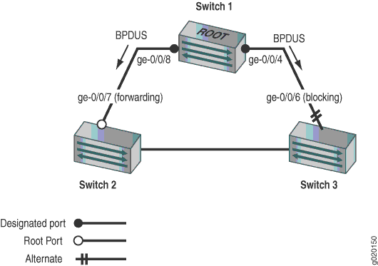
Table 4 shows the components that will be configured for loop protection.
Property |
Settings |
|---|---|
Switch 1 |
Switch 1 is the root bridge. |
Switch 2 |
Switch 2 has the root port ge-0/0/7. |
Switch 3 |
Switch 3 is connected to Switch 1 through interface ge-0/0/6. |
A spanning-tree topology contains ports that have specific roles:
The root port is responsible for forwarding data to the root bridge.
The alternate port is a standby port for the root port. When a root port goes down, the alternate port becomes the active root port.
The designated port forwards data to the downstream network segment or device.
This configuration example uses an RSTP topology. However, you also can configure loop protection for STP or MSTP topologies at the [edit protocols (mstp | stp)] hierarchy level.
Configuration
To configure loop protection on an interface:
Procedure
CLI Quick Configuration
To quickly configure loop protection on interface ge-0/0/6:
[edit]
                         set protocols rstp interface ge-0/0/6 bpdu-timeout-action block
Step-by-Step Procedure
To configure loop protection:
Configure interface ge-0/0/6 on Switch 3:
[edit protocols rstp]
user@switch# set interface ge-0/0/6 bpdu-timeout-action block
Results
Check the results of the configuration:
user@switch> show configuration protocols rstp
interface ge-0/0/6.0 {
    bpdu-timeout-action {
        block;
    }
}
Verification
To confirm that the configuration is working properly, perform these tasks:
- Displaying the Interface State Before Loop Protection Is Triggered
- Verifying That Loop Protection Is Working on an Interface
Displaying the Interface State Before Loop Protection Is Triggered
Purpose
Before loop protection is triggered on interface ge-0/0/6, confirm that the interface is blocking.
Action
Use the operational mode command:
user@switch>                              show spanning-tree interface

Spanning tree interface parameters for instance 0

Interface    Port ID    Designated      Designated         Port    State  Role
                         port ID        bridge ID          Cost
ge-0/0/0.0     128:513      128:513  32768.0019e2503f00     20000  BLK    DIS
ge-0/0/1.0     128:514      128:514  32768.0019e2503f00     20000  BLK    DIS
ge-0/0/2.0     128:515      128:515  32768.0019e2503f00     20000  BLK    DIS
ge-0/0/3.0     128:516      128:516  32768.0019e2503f00     20000  FWD    DESG
ge-0/0/4.0     128:517      128:517  32768.0019e2503f00     20000  FWD    DESG
ge-0/0/5.0     128:518      128:518  32768.0019e2503f00     20000  FWD    DESG
ge-0/0/6.0     128:519        128:2  16384.00aabbcc0348     20000  BLK    ALT
[output truncated]
Meaning
The output from the operational mode command show
spanning-tree interface shows that ge-0/0/6.0 is the
alternate port and in a blocking state.
Verifying That Loop Protection Is Working on an Interface
Purpose
Verify the loop protection configuration on interface ge-0/0/6. RSTP has been disabled on interface ge-0/0/4 on Switch 1. This will stop BPDUs from being sent to interface ge-0/0/6 and trigger loop protection on the interface.
Action
Use the operational mode command:
user@switch>                              show spanning-tree interface

Spanning tree interface parameters for instance 0

Interface    Port ID    Designated      Designated         Port    State  Role
                         port ID        bridge ID          Cost
ge-0/0/0.0     128:513      128:513  32768.0019e2503f00     20000  BLK    DIS
ge-0/0/1.0     128:514      128:514  32768.0019e2503f00     20000  BLK    DIS
ge-0/0/2.0     128:515      128:515  32768.0019e2503f00     20000  BLK    DIS
ge-0/0/3.0     128:516      128:516  32768.0019e2503f00     20000  FWD    DESG
ge-0/0/4.0     128:517      128:517  32768.0019e2503f00     20000  FWD    DESG
ge-0/0/5.0     128:518      128:518  32768.0019e2503f00     20000  FWD    DESG
ge-0/0/6.0     128:519      128:519  32768.0019e2503f00     20000  BLK    DIS (Loop-Incon)
[output truncated]
Meaning
The operational mode command show spanning-tree
interface shows that interface ge-0/0/6.0 has detected
that BPDUs are no longer being forwarded to it and has moved into
a loop-inconsistent state. The loop-inconsistent state prevents the
interface from transitioning to a forwarding state. The interface
recovers and transitions back to its original state as soon as it
receives BPDUs.
Example: Configuring Loop Protection to Prevent Interfaces from Transitioning from Blocking to Forwarding in a Spanning Tree on EX Series Switches With ELS
This example uses Junos OS for EX Series switches with support for the Enhanced Layer 2 Software (ELS) configuration style. If your switch runs software that does not support ELS, see Example: Configuring Loop Protection to Prevent Interfaces from Transitioning from Blocking to Forwarding in a Spanning Tree on non-ELS EX Series Switches. For ELS details, see Using the Enhanced Layer 2 Software CLI.
EX Series switches provide Layer 2 loop prevention through Spanning Tree Protocol (STP), Rapid Spanning Tree protocol (RSTP), and Multiple Spanning Tree Protocol (MSTP). Loop protection increases the efficiency of STP, RSTP, and MSTP by preventing interfaces from moving into a forwarding state that would result in a loop opening up in the network.
This example describes how to configure loop protection for an interface on an EX Series switch in an RSTP topology:
Requirements
This example uses the following software and hardware components:
Junos OS Release 13.2X50-D10 or later or later for EX Series switches
Three EX Series switches in an RSTP topology
Before you configure the interface for loop protection, be sure you have:
RSTP operating on the switches.
By default, RSTP is enabled on all EX Series switches.
Overview and Topology
A loop-free network in spanning-tree topologies is supported through the exchange of a special type of frame called bridge protocol data unit (BPDU). Peer STP applications running on the switch interfaces use BPDUs to communicate. Ultimately, the exchange of BPDUs determines which interfaces block traffic (preventing loops) and which interfaces become root ports and forward traffic.
A blocking interface can transition to the forwarding state in error if the interface stops receiving BPDUs from its designated port on the segment. Such a transition error can occur when there is a hardware error on the switch or software configuration error between the switch and its neighbor. When this happens, a loop opens up in the spanning tree. Loops in a Layer 2 topology cause broadcast, unicast, and multicast frames to continuously circle the looped network. As a switch processes a flood of frames in a looped network, its resources become depleted and the ultimate result is a network outage.
An interface can be configured for either loop protection or root protection, but not for both.
Three EX Series switches are displayed in Figure 6. In this example, they are configured for RSTP and create a loop-free topology. Interface ge-0/0/6 is blocking traffic between Switch 3 and Switch 1; thus, traffic is forwarded through interface ge-0/0/7 on Switch 2. BPDUs are being sent from the root bridge on Switch 1 to both of these interfaces.
This example shows how to configure loop protection on interface ge-0/0/6 to prevent it from transitioning from a blocking state to a forwarding state and creating a loop in the spanning-tree topology.
Topology
Table 5 shows the components that will be configured for loop protection.
Property |
Settings |
|---|---|
Switch 1 |
Switch 1 is the root bridge. |
Switch 2 |
Switch 2 has the root port ge-0/0/7. |
Switch 3 |
Switch 3 is connected to Switch 1 through interface ge-0/0/6. |
A spanning-tree topology contains ports that have specific roles:
The root port is responsible for forwarding data to the root bridge.
The alternate port is a standby port for the root port. When a root port goes down, the alternate port becomes the active root port.
The designated port forwards data to the downstream network segment or device.
This configuration example uses an RSTP topology. However, you also can configure loop protection for MSTP topologies at the [edit protocols mstp ] hierarchy level.
Configuration
To configure loop protection on an interface:
Procedure
CLI Quick Configuration
To quickly configure loop protection on interface ge-0/0/6:
[edit]
                         set protocols rstp interface ge-0/0/6 bpdu-timeout-action block
Step-by-Step Procedure
To configure loop protection:
Configure interface ge-0/0/6 on Switch 3:
[edit protocols rstp]
user@switch# set interface ge-0/0/6 bpdu-timeout-action block
Results
Check the results of the configuration:
user@switch> show configuration protocols rstp
interface ge-0/0/6 {
    bpdu-timeout-action {
        block;
    }
}
Verification
To confirm that the configuration is working properly, perform these tasks:
- Displaying the Interface State Before Loop Protection Is Triggered
- Verifying That Loop Protection Is Working on an Interface
Displaying the Interface State Before Loop Protection Is Triggered
Purpose
Before loop protection is triggered on interface ge-0/0/6, confirm that the interface is blocking.
Action
Use the operational mode command:
user@switch>                              show spanning-tree interface

Spanning tree interface parameters for instance 0

Interface    Port ID    Designated      Designated         Port    State  Role
                         port ID        bridge ID          Cost
ge-0/0/0     128:513      128:513  32768.0019e2503f00     20000  BLK    DIS
ge-0/0/1     128:514      128:514  32768.0019e2503f00     20000  BLK    DIS
ge-0/0/2     128:515      128:515  32768.0019e2503f00     20000  BLK    DIS
ge-0/0/3     128:516      128:516  32768.0019e2503f00     20000  FWD    DESG
ge-0/0/4     128:517      128:517  32768.0019e2503f00     20000  FWD    DESG
ge-0/0/5     128:518      128:518  32768.0019e2503f00     20000  FWD    DESG
ge-0/0/6     128:519        128:2  16384.00aabbcc0348     20000  BLK    ALT
[output truncated]
Meaning
The output from the operational mode command show
spanning-tree interface shows that ge-0/0/6 is the
alternate port and in a blocking state.
Verifying That Loop Protection Is Working on an Interface
Purpose
Verify the loop protection configuration on interface ge-0/0/6. RSTP has been disabled on interface ge-0/0/4 on Switch 1. This will stop BPDUs from being sent to interface ge-0/0/6 and trigger loop protection on the interface.
Action
Use the operational mode command:
user@switch>                              show spanning-tree interface

Spanning tree interface parameters for instance 0

Interface    Port ID    Designated      Designated         Port    State  Role
                         port ID        bridge ID          Cost
ge-0/0/0     128:513      128:513  32768.0019e2503f00     20000  BLK    DIS
ge-0/0/1     128:514      128:514  32768.0019e2503f00     20000  BLK    DIS
ge-0/0/2     128:515      128:515  32768.0019e2503f00     20000  BLK    DIS
ge-0/0/3     128:516      128:516  32768.0019e2503f00     20000  FWD    DESG
ge-0/0/4     128:517      128:517  32768.0019e2503f00     20000  FWD    DESG
ge-0/0/5     128:518      128:518  32768.0019e2503f00     20000  FWD    DESG
ge-0/0/6     128:519      128:519  32768.0019e2503f00     20000  BLK    DIS (Loop-Incon)
[output truncated]
Meaning
The operational mode command show spanning-tree
interface shows that interface ge-0/0/6 has detected
that BPDUs are no longer being forwarded to it and has moved into
a loop-inconsistent state. The loop-inconsistent state prevents the
interface from transitioning to a forwarding state. To clear the BPDU
error, issue the operational mode command clear error bpdu interface on the
switch. The interface recovers and transitions back to its original
state as soon as it receives BPDUs.