ON THIS PAGE
Example: Transporting IPv6 Traffic Across IPv4 Using Filter-Based Tunneling
This example shows how to configure a unidirectional generic routing encapsulation (GRE) tunnel to transport IPv6 unicast transit traffic across an IPv4 transport network. To provide network connectivity to the two disjoint IPv6 networks, two MX Series 5G Universal Routing Platforms are configured with interfaces that can originate and understand both IPv4 and IPv6 packets. The configuration does not require the creation of tunnel interfaces on Tunnel Services physical interface cards (PICs) or on MPC3E Modular Port Concentrators (MPCs). Instead, you attach firewall filters to Ethernet logical interfaces hosted on Modular Interface Cards (MICs) or MPCs in the two MX Series routers.
Requirements
This example uses the following Juniper Networks hardware and Junos OS software:
Transport network—An IPv4 network running Junos OS Release 12.3R2 or later.
PE routers—Two MX80 routers installed as provider edge (PE) routers that connect the IPv4 network to two disjoint IPv6 networks that require a logical path from one network to the other.
Encapsulating interface—On the encapsulator (the ingress PE router), one Ethernet logical interface configured on the built-in 10-Gigabit Ethernet MIC.
De-encapsulating interfaces—On the de-encapsulator (the egress PE router), Ethernet logical interfaces configured on three ports of the built-in 10-Gigabit Ethernet MIC.
Before you begin configuring this example:
On each PE router, use the show chassis fpc pic-status operational mode command to determine which router line cards support filter-based GRE IPv4 tunneling and then use the
interfacesconfiguration statement to configure encapsulating and de-encapsulating interfaces.At PE1, the encapsulator, configure one encapsulating interface on a supported line card.
At PE2, the de-encapsulator, configure three de-encapsulating interfaces on a supported line card.
Check that IPv4 routing protocols are enabled across the network to support routing paths from the encapsulator to the de-encapsulator.
Configure routing information by manually adding static routes to route tables or by configuring static or dynamic route-sharing protocols. For more information, see Transport and Internet Protocols User Guide.
At PE1, ping the PE2 IPv4 loopback address to verify that the de-encapsulator is reachable from the encapsulator.
At PE2, ping the CE2 router IPv6 loopback address to verify that the destination customer edge router is reachable from the de-encapsulator..
IPv6 routing paths from PE2 to CE2 can be provided by static routes manually added to routing tables or by static or dynamic route-sharing protocols.
By default, PE2 forwards packets based on interface routes (direct routes) imported from the primary routing table.
As an option, the de-encapsulating filter can specify that the Packet Forwarding Engine uses an alternate routing table to forward payload packets to the destination customer network. In an optional configuration task in this example, you specify an alternate routing table by installing static routes from PE2 to C1 in the routing instance blue. You configure the routing information base (RIB) group blue_group to specify that the route information of inet6.0 is shared with blue.inet6.0, then you associate the PE2 interfaces with routes stored in both the default routes and the routing instance.
Overview
In this example you configure a unidirectional filter-based GRE IPv4 tunnel from Router PE1 to Router PE2, providing a logical path from IPv6 network C1 to IPv6 network C2.
To enable bidirectional filter-based GRE tunneling, you must configure a second tunnel in the reverse direction.
As an optional task in this example, you can create a RIB group, which specifies the sharing of routing information (including routes learned from peers, local routes resulting from the application of protocol policies to the learned routes, and the routes advertised to peers) of multiple routing tables.
Topology
Figure 1 shows the path of IPv6 traffic transported from network C1 to network C2, across an IPv4 transport network using a filter-based tunnel from PE1 to PE2 and without requiring tunnel interfaces.
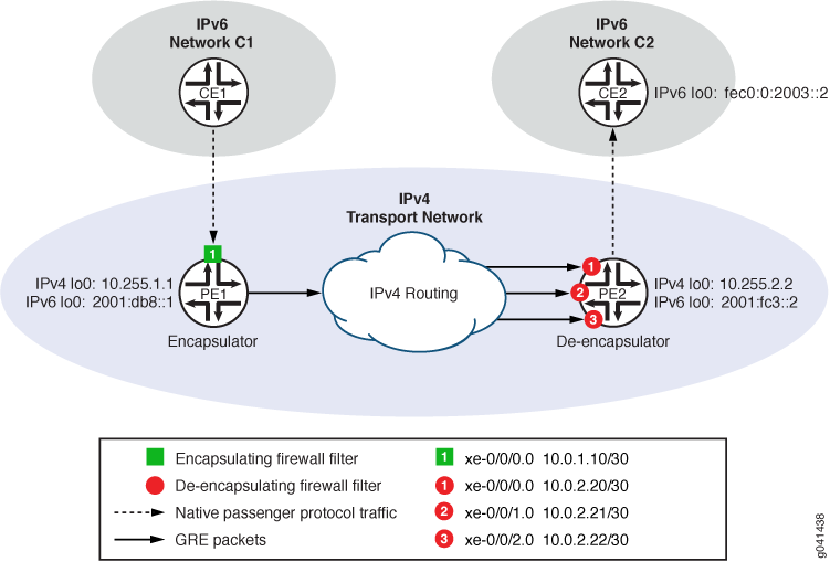
Table 1 summarizes the configuration of Router PE1 as the encapsulator. Table 2 summarizes the configuration of Router PE2 as the de-encapsulator.
Component |
CLI Names |
Description |
||
|---|---|---|---|---|
|
Encapsulator |
Device name:IPv4 loopback:IPv6 loopback: |
|
MX80 router installed as an ingress PE router. PE1 connects the IPv4 network the customer edge router CE1 in the IPv6 source network C1. |
Encapsulating interface |
Interface name:IPv4 address:IPv6 address: |
|
Customer-facing logical interface hosted on a 10-Gigabit Ethernet MIC. CE1 sends this interface IPv6 traffic that originates at end-user hosts and is destined for applications or hosts on the IPv6 destination network C2. |
|
Encapsulation filter |
Filter name: |
|
IPv6 firewall filter whose action causes the Packet Forwarding Engine to encapsulate matched packets using the specified tunnel characteristics. Encapsulation consists of adding a GRE header, adding an IPv4 packet header, and then forwarding the resulting GRE packet through the GRE IPv4 tunnel. |
|
Tunnel source interface |
Interface name:IPv4 address: |
|
Core-facing egress interface to the tunnel. |
|
GRE tunnel template |
Tunnel name: |
|
Defines the GRE IPv4 tunnel from Router PE1 ( |
|
Component |
CLI Names |
Description |
||
|---|---|---|---|---|
|
De-encapsulator |
Device name:IPv4 loopback:IPv6 loopback: |
|
MX80 router installed as an egress PE router to receive GRE packets forwarded from ingress router PE1 across a GRE IPv4 tunnel. |
De-encapsulating interfaces |
Interface name:IPv4 address: Interface name:IPv4 address: Interface name:IPv4 address: |
|
Core-facing ingress logical interfaces hosted on 10-Gigabit Ethernet MICs. The interfaces receive GRE packets routed through the GRE IPv4 tunnel from PE1. |
|
De-encapsulation filter |
Filter name: |
|
IPv4 firewall filter that applies the decapsulate action to GRE packets. The filter action causes the Packet Forwarding Engine to de-encapsulate matched packets. De-encapsulation consists of removing the outer GRE header and then forwarding the inner IPv6 payload packet to its original destination on the destination IPv6 network by performing destination lookup on the default routing table. |
|
Tunnel egress interface |
Interface name:IPv4 address:IPv6 address: |
|
Customer-facing interface though which the router forwards de-encapsulated IPv6 packets to the destination IPv6 network C2. |
|
Configuration
To transport IPv6 packets from CE1 to CE2 across an IPv4 transport network using a filter-based tunnel from PE1 to PE2 and without configuring tunnel interfaces, perform these tasks:
- CLI Quick Configuration
- Configuring PE1 to Encapsulate IPv6 Packets
- Configuring PE2 to De-Encapsulate GRE Packets
- Optional: Configuring PE2 with an Alternate Routing Table
CLI Quick Configuration
To quickly configure this example, copy the following commands, paste them into a text file, remove any line breaks, change any details necessary to match your network configuration, and then copy and paste the commands into the CLI at the [edit] hierarchy level.
Configuring PE1 to Encapsulate IPv6 Packets
set interfaces lo0 unit 0 family inet address 10.255.1.1
set interfaces lo0 unit 0 family inet6 address 2001:db8::1
set interfaces xe-0/0/0 unit 0 family inet address 10.0.1.10/30
set interfaces xe-0/0/0 unit 0 family inet6 address 2001::10.34.1.10/120
set interfaces xe-0/0/0 unit 0 family inet6 filter input gre_encap_1
set interfaces xe-0/0/2 unit 0 family inet address 10.0.1.12/30
set firewall family inet6 filter gre_encap_1 term t1 then count c_gre_encap_1
set firewall family inet6 filter gre_encap_1 term t1 then encapsulate tunnel_1
set firewall tunnel-end-point tunnel_1 ipv4 source-address 10.255.1.1
set firewall tunnel-end-point tunnel_1 ipv4 destination-address 10.255.2.2
set firewall tunnel-end-point tunnel_1 gre
Configuring PE2 to De-Encapsulate GRE Packets
set interfaces lo0 unit 0 family inet address 10.255.2.2
set interfaces lo0 unit 0 family inet6 address 2001:fc3::2
set interfaces xe-0/0/0 unit 0 family inet address 10.0.2.20/30
set interfaces xe-0/0/1 unit 0 family inet address 10.0.2.21/30
set interfaces xe-0/0/2 unit 0 family inet address 10.0.2.22/30
set interfaces xe-0/0/3 unit 0 family inet address 10.0.2.23/30
set interfaces xe-0/0/3 unit 0 family inet6 address ::20.34.2.23/120
set forwarding-options family inet filter input gre_decap_1
set firewall family inet filter gre_decap_1 term t1 from source-address 10.255.1.1/32
set firewall family inet filter gre_decap_1 term t1 from destination-address 10.255.2.2/32
set firewall family inet filter gre_decap_1 term t1 then count c_gre_decap_1
set firewall family inet filter gre_decap_1 term t1 then decapsulate gre
Optional: Configuring PE2 with an Alternate Routing Table
set routing-instances blue instance-type forwarding
set routing-instances blue routing-options rib blue.inet6.0 static route 0::/0 next-hop fec0:0:2003::2
set routing-options passive
set routing-options rib inet6.0
set routing-options rib-groups blue_group import-rib inet6.0
set routing-options rib-groups blue_group import-rib blue.inet6.0
set routing-options interface-routes rib-group inet6 blue_group
set firewall family inet filter gre_decap_1 term t1 then decapsulate gre routing-instance blue
Configuring PE1 to Encapsulate IPv6 Packets
Step-by-Step Procedure
To configure Router PE1 to encapsulate IPv6 packets arriving from CE1:
Configure the router loopback addresses.
[edit]
user@PE1# set interfaces lo0 unit 0 family inet address 10.255.1.1
user@PE1# set interfaces lo0 unit 0 family inet6 address 2001:db8::1
Configure the encapsulating interface IPv4 and IPv6 addresses and attach the encapsulating filter to the IPv6 input.
[edit]
user@PE1# set interfaces xe-0/0/0 unit 0 family inet address 10.0.1.10/30
user@PE1# set interfaces xe-0/0/0 unit 0 family inet6 address ::10.34.1.10/120
user@PE1# set interfaces xe-0/0/0 unit 0 family inet6 filter input gre_encap_1
Configure the core-facing egress interface to the tunnel.
[edit]
user@PE2# set interfaces xe-0/0/2 unit 0 family inet address 10.0.1.12/30
Define an IPv6 firewall filter that causes the Packet Forwarding Engine to encapsulate all packets.
[edit]
user@PE1# set firewall family inet6 filter gre_encap_1 term t1 then count c_gre_encap_1
user@PE1# set firewall family inet6 filter gre_encap_1 term t1 then encapsulate tunnel_1
Note:The encapsulate firewall filter action is a terminating filter action. A filter-terminating action halts all evaluation of a firewall filter for a specific packet. The router performs the specified action, and no additional terms are examined.
Define a GRE IPv4 tunnel template named tunnel_1 that specifies the host IP addresses of the one tunnel source interface and three tunnel destination interfaces.
[edit]
user@PE1# set firewall tunnel-end-point tunnel_1 ipv4 source-address 10.255.1.1
user@PE1# set firewall tunnel-end-point tunnel_1 ipv4 destination-address 10.255.2.2
user@PE1# set firewall tunnel-end-point tunnel_1 gre
Note:You can tunnel multiple but distinct flows from 10.0.1.10 (the tunnel source interface on PE1) to 10.0.2.20 – 10.0.2.22 (the de-encapsulating interfaces on PE2) if you use the GRE option key number to uniquely identify each tunnel.
If you are done configuring the device, commit the configuration.
[edit ]
user@PE1# commit
Results
From configuration mode, confirm your configuration by entering the show firewall and show interfaces commands. If the output does not display the intended configuration, repeat the instructions in this example to correct the configuration.
Router PE1
Confirm the firewall filter and tunnel template on the encapsulator.
user@PE2# show firewall
family inet6 {
    filter gre_encap_1 {
        term t1 {
            then {
                count c_gre_encap_1;
                encapsulate tunnel_1;
            }
        }
    }
}
tunnel-end-point tunnel_1 {
    ipv4 {
        source-address 10.255.1.1;
        destination-address 10.255.2.2;
    }
    gre;
}
Router PE1
Confirm the interfaces on the encapsulator.
user@PE1# show interfaces
lo0 {
    unit 0 {
        family inet {
            address 10.255.1.1;
        }
        family inet6 {
            address 2001:db8::1;
        }
    }
}
xe-0/0/0 {
    unit 0 {
        family inet {
            address 10.0.1.10/30;
        }
        family inet6 {
            address ::10.34.1.10/120;
            filter input gre_encap_1;
        }
    }
}
xe-0/0/2 {
    unit 0 {
        family inet {
            address 10.0.1.12/30;
        }
    }
}
Configuring PE2 to De-Encapsulate GRE Packets
Step-by-Step Procedure
To configure Router PE2 to de-encapsulate GRE packets arriving from the IPv4 tunnel:
Configure the router loopback address.
[edit]
user@PE2# set interfaces lo0 unit 0 family inet address 10.255.2.2
user@PE2# set interfaces lo0 unit 0 family inet6 address 2001:fc3::2
Configure the de-encapsulating interfaces.
[edit]
user@PE2# set interfaces xe-0/0/0 unit 0 family inet address 10.0.2.20/30
user@PE2# set interfaces xe-0/0/1 unit 0 family inet address 10.0.2.21/30
user@PE2# set interfaces xe-0/0/2 unit 0 family inet address 10.0.2.22/30
Configure the customer-facing egress interface to CE2.
[edit]
user@PE2# set interfaces xe-0/0/3 unit 0 family inet address 10.0.2.23/30
user@PE2# set interfaces xe-0/0/3 unit 0 family inet6 address ::20.34.2.23/120
Apply the ingress de-encapsulating firewall filter to all forwarded packets.
[edit]
user@PE2# set forwarding-options family inet filter input gre_decap_1
Define IPv4 filter gre_decap_1.
Define an IPv4 filter that de-encapsulates and forwards all GRE packets.
[edit]
user@PE2# set firewall family inet filter gre_decap_1
Configure term t1 to match packets transported across the tunnel tunnel_1 defined on Router PE1. The tunnel sends packets from Router PE1 (configured with IPv4 loopback address 10.255.1.1) to Router PE2 (configured with IPv4 loopback address 10.255.2.2).
[edit firewall family inet filter gre_decap_1]
user@PE2# set term t1 from source-address 10.255.1.1
user@PE2# set  term t1 from destination-address 10.255.2.2
Configure term t1 to count and de-encapsulate matched packets.
[edit firewall family inet filter gre_decap_1]
user@PE2# set term t1 then count c_gre_decap_1
user@PE2# set term t1 then decapsulate gre
If the de-encapsulating filter action decapsulate references the blue routing instance, make sure that the routing instance is configured and that the RIB group blue_group defines the sharing of the alternate routes into the primary table.
If you are done configuring the device, commit the configuration.
[edit]
user@PE2# commit
Results
From configuration mode, confirm your configuration by entering the show firewall, show forwarding-options, and show interfaces commands. If the output does not display the intended configuration, repeat the instructions in this example to correct the configuration.
Router PE2
Confirm the firewall filter on the de-encapsulator.
user@PE2# show firewall
family inet {
    filter gre_decap_1 {
        term t1 {
            from {
                source-address 10.255.1.1;
                destination-address 10.255.2.2;
            }
            then {
                count c_gre_decap_1;
                decapsulate gre routing-instance blue;
            }
        }
    }
}
If the de-encapsulating filter action decapsulate references the blue routing instance, make sure that the routing instance is configured and that the RIB group blue_group defines the sharing of the alternate routes into the primary table.
Router PE2
Confirm the forwarding options (for attaching the de-encapsulating firewall filter to all input forwarded packets) on the de-encapsulator.
user@PE2# show forwarding-options
forwarding-options {
    family inet {
        filter {
            input gre_decap_1;
        }
    }
}
Router PE2
Confirm the interfaces on the de-encapsulator.
user@PE2# show interfaces
lo0 {
    unit 0 {
        family inet {
            address 10.255.2.2;
        }
        family inet6 {
            address 2001:fc3::2;
        }
    }
}
xe-0/0/0 {
    unit 0 {
        family inet {
            address 10.0.2.20/30;
            filter input gre_decap_1;
        }
    }
}
xe-0/0/1 {
    unit 0 {
        family inet {
            address 10.0.2.21/30;
            filter input gre_decap_1;
        }
    }
}
xe-0/0/2 {
    unit 0 {
        family inet {
            address 10.0.2.22/30;
            filter input gre_decap_1;
        }
    }
}
xe-0/0/3 {
    unit 0 {
        family inet {
            address 10.0.2.23/30;
        }
        family inet6 {
            address ::20.34.2.23/120;
        }
    }
}
Optional: Configuring PE2 with an Alternate Routing Table
Step-by-Step Procedure
To configure Router PE2 with an alternate routing table:
Configure the routing instance blue, and add static routes to CE2.
[edit ]
user@PE2# set routing-instances blue instance-type forwarding
user@PE2# set routing-instances blue routing-options rib blue.inet6.0 static route 0::/0 next-hop fec0:0:2003::2
The Junos OS software generates the routing table blue.inet6.0 using the routing information learned within the instance.
Enable routes to remain in routing and forwarding tables, even if the routes become inactive. This allows a static route to remain in the table if the next hop is unavailable.
[edit ]
user@PE2# set routing-options passive
Create a RIB group by explicitly creating the default routing table.
[edit ]
user@PE2# set routing-options rib inet6.0
Define the RIB group blue_group.
[edit ]
user@PE2# set routing-options rib-groups blue_group import-rib inet6.0
user@PE2# set routing-options rib-groups blue_group import-rib blue.inet6.0
In the import-rib statement, specify the primary routing table first.
Associate the router interfaces with routing information specified by the RIB group.
[edit ]
user@PE2# set routing-options interface-routes rib-group inet6 blue_group
If you are done configuring the device, commit the configuration.
[edit ]
user@PE2# commit
Results
From configuration mode, confirm your configuration by entering the show firewall, show routing-instances, and show routing-optionscommands. If the output does not display the intended configuration, repeat the instructions in this example to correct the configuration.
Router PE2
If you configured an alternate routing table on Router PE2, confirm the routing instance configuration.
user@PE2# show routing-instances
blue {
    instance-type forwarding;
    routing-options {
        static route 0::/0 next-hop fec0:0:2003::2;
    }
}
Router PE2
If you configured an alternate routing table on Router PE2, confirm the RIB group and direct routing configurations.
user@PE2# show routing-options
interface-routes {
    rib-group blue_group;
}
passive;
rib inet6.0;
rib-groups {
    blue_group {
        import-rib [ inet6.0 blue.inet6.0 ];
    }
}
Verification
Confirm that the configurations are working properly.
- Verifying Routing Information
- Verifying Encapsulation on PE1
- Verifying De-Encapsulation on PE2
- Platform-Specific Behavior
Verifying Routing Information
Purpose
Verify that the direct routes include the alternate routing table information.
Action
To perform the verification:
(Optional) To verify the routing instance blue on PE2, use the show route instance operational mode command to display the primary table and number of routes for that routing instance.
user@PE2> show route instance blue summary
Instance             Type
         Primary RIB                                     Active/holddown/hidden
blue                 forwarding
         blue.inet6.0                                    2/0/0
(Optional) To view the routing table associated with the routing instance blue on PE2, use the show route table operational mode command
user@PE2> show route table blue.inet6.0

blue.inet6.0: 2 destinations, 2 routes (2 active, 0 holddown, 0 hidden)
+ = Active Route, - = Last Active, * = Both

2001:db8::192:168:239:17/128
                   *[Direct/0] 00:02:26
                    > via lo0.0
fe80::2a0:a50f:fc64:e032/128
                   *[Direct/0] 00:02:26
                    > via lo0.0
(Optional) To verify that the alternate routes from routing instance blue have been imported to the PE2 forwarding table, use the show route forwarding-table operational mode command to display the contents of the router forwarding table and the routing instance forwarding table.
user@PE2> show route forwarding-table blue
Routing table: blue.inet
Internet:
Destination        Type RtRef Next hop           Type Index NhRef Netif
default            perm     0                    rjct   689     1
0.0.0.0/32         perm     0                    dscd   687     1
172.16.233.0/4        perm     0                    mdsc   688     1
172.16.233.1/32       perm     0 172.16.233.1          mcst   684     1
255.255.255.255/32 perm     0                    bcst   685     1

Routing table: blue.iso
ISO:
Destination        Type RtRef Next hop           Type Index NhRef Netif
default            perm     0                    rjct   695     1

Routing table: blue.inet6
Internet6:
Destination        Type RtRef Next hop           Type Index NhRef Netif
default            perm     0                    rjct   701     1
::/128             perm     0                    dscd   699     1
2001:db8::192:168:239:17/128
                   user     0                    rtbl     2     3
fe80::2a0:a50f:fc64:e032/128
                   user     0                    rtbl     2     3
ff00::/8           perm     0                    mdsc   700     1
ff02::1/128        perm     0 ff02::1            mcst   697     1
Verifying Encapsulation on PE1
Purpose
Verify the encapsulating interface on PE1.
Action
To perform the verification:
Use the show interfaces filters operational mode command to verify that the encapsulating firewall filter is attached to the ingress of the encapsulating interface.
user@PE1> show interfaces filters xe-0/0/0.0
Interface        Admin  Link  Proto  Input Filter        Output Filter
xe-0/0/0.0       up     down  inet6  gre_encap_1
Use the show interfaces operational mode command to verify that the encapsulating interface is receiving packets.
user@PE1> show interfaces xe-0/0/0.0 detail | filter ”Ingress traffic”
...
Physical interface: xe-0/0/0, Enabled, Physical link is Up
...
  Ingress traffic statistics at Packet Forwarding Engine:
   Input  bytes  :           6970299398                    0 bps
   Input  packets:             81049992                    0 pps
   Drop   bytes  :                    0                    0 bps
   Drop   packets:                    0                    0 pps
...
Use the show firewall filter operational mode command to verify that ingress passenger protocol traffic triggers the encapsulating filter.
user@PE1> show firewall filter gre_encap_1
Filter: gre_encap_1
Counters:
Name                            Bytes             Packets
c_gre_encap_1              6970299398            81049992
Meaning
If the encapsulating filter is attached to the encapsulating interface, and the encapsulating interface receives passenger protocol traffic, and the firewall filter statistics show that ingress passenger protocol traffic is being encapsulated, then GRE packets are being forwarded through the tunnel.
Verifying De-Encapsulation on PE2
Purpose
Verify the de-encapsulating interfaces on PE2.
Action
To perform the verification:
On PE1, use the ping operational mode command to verify that PE2 is reachable.
user@PE1> ping 10.255.2.2
PING 10.255.2.2 (10.255.2.2): 56 data bytes
64 bytes from 10.255.2.2: icmp_seq=0 ttl=64 time=0.576 ms
64 bytes from 10.255.2.2: icmp_seq=1 ttl=64 time=0.269 ms
^C [abort]
On PE2, use the show interfaces filter operational mode command to verify that the de-encapsulating firewall filter is attached to the ingress of the de-encapsulating interfaces.
user@PE2> show interfaces filter | match xe-
Interface        Admin  Link  Proto  Input Filter        Output Filter
xe-0/0/0.0       up     down  inet   gre_decap_1
xe-0/0/1.0       up     down  inet   gre_decap_1
xe-0/0/2.0       up     down  inet   gre_decap_1
On PE2, use the show interfaces operational mode command to verify that the de-encapsulating interfaces are receiving packets.
user@PE2> show interfaces xe-0/0/0.0 detail | filter ”Ingress traffic”
Physical interface: xe-0/0/0, Enabled, Physical link is Up
 ...
  Ingress traffic statistics at Packet Forwarding Engine:
   Input  bytes  :           6970299398                    0 bps
   Input  packets:             81049992                    0 pps
   Drop   bytes  :                    0                    0 bps
   Drop   packets:                    0                    0 pps
 ...


user@PE2> show interfaces xe-0/0/1.0 detail | filter ”Ingress traffic”
Physical interface: xe-0/0/2, Enabled, Physical link is Up
 ...


user@PE2> show interfaces xe-0/0/2.0 detail | filter ”Ingress traffic”
Physical interface: xe-0/0/2, Enabled, Physical link is Up
 ...
Depending on how routing is configured and which links are up and which links are down, some of the de-encapsulating interfaces might not be receiving packets although the tunnel is operating properly.
On PE2, use the show firewall filter operational mode command to verify that ingress GRE traffic triggers the de-encapsulating filter.
user@PE2> show firewall filter gre_decap_1

Filter: gre_decap_1
Counters:
Name                                                Bytes              Packets
c_gre_decap_1                                  6970299398             81049992
Meaning
The verification confirms the following operational states and activities of the encapsulator:
PE2 is reachable from the PE1.
The de-encapsulating filter is attached to the input of all de-encapsulating interfaces.
The de-encapsulator is receiving traffic at de-encapsulating interfaces as expected.
GRE packets received at the de-encapsulating interfaces trigger the de-encapsulating firewall filter action.
Platform-Specific Behavior
Use Feature Explorer to confirm platform and release support for specific features.
Use the following table to review platform-specific behaviors for your platform:
|
Platform |
Difference |
|---|---|
|
PTX Series routers |
Filter-based GRE tunneling is supported on PTX Series routers
only when network services is set to
|