Components of Filter-Based Tunneling Across IPv4 Networks
Topology of Filter-Based Tunneling Across IPv4 Networks
Filter-based generic routing encapsulation (GRE) tunneling is
supported on PTX Series routers only when network services is set
to enhanced-mode. For more information, see
enhanced-mode
.
Figure 1 shows the path of passenger protocol packets from customer network C1 as they are transported across a service provider IPv4 network to customer network C2.
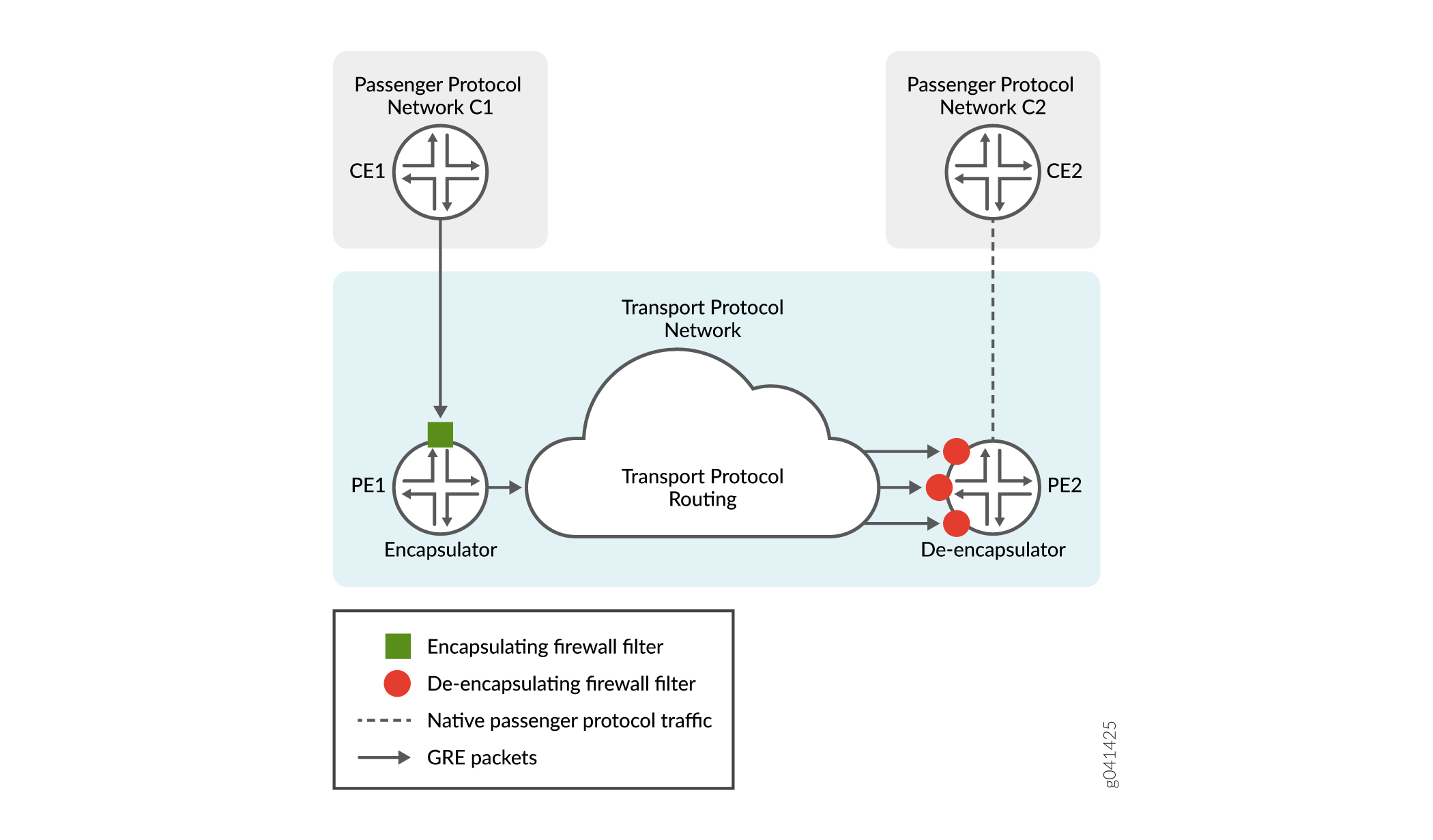
In this example topology, C1 and C2 are disjoint networks that lack a native routing path between them. The IPv4 transport network is configured with a unidirectional generic routing encapsulation (GRE) tunnel from PE1 to PE2 using firewall filters and without requiring tunnel interfaces. The GRE tunnel from PE1 to PE2 provides a logical path from C1 to C2 across the IPv4 transport network.
Routing of GRE Packets Across the Tunnel
Traffic flows through the tunnel provided that PE2 is routable from PE1. Routing paths from PE1 to PE2 can be provided by static routes manually added to routing tables or by static or dynamic route-sharing protocols.
Routing of Passenger Protocol Packets from PE2 to C2
By default, PE2 forwards packets based on interface routes (direct routes) imported from the primary routing table. As an option, the de-encapsulating filter can specify that the Packet Forwarding Engine uses an alternate routing table to forward payload packets to the destination customer network. Specify the alternate routing table in a routing instance installed with routes into C2, then use a routing information base (RIB) group definition to share the primary routes with the alternate routes. A RIB group specifies the sharing of routing information (including routes learned from peers, local routes resulting from the application of protocol policies to the learned routes, and the routes advertised to peers) of multiple routing tables.
Terminology at the Network Layer Protocols Level
In filter-based tunneling across an IPv4 network, the network-layer protocols are described in the following terms:
| passenger protocol |
The type of protocol (IPv4, IPv6, or MPLS) used by the networks that are connected by a GRE tunnel. Packets that are encapsulated and routed across the transport network are payload packets. |
| encapsulation protocol |
The type of network layer protocol (GRE) used to encapsulate passenger protocol packets so that the resulting GRE packets can be carried over the transport protocol network as the packet payload. |
| transport protocol |
The type of protocol (IPv4) used by the network that routes passenger protocol packets through a GRE tunnel. The transport protocol is also called the delivery protocol. |
Terminology at the Ingress PE Router
In filter-based tunneling across an IPv4 network, an egress PE router is described in the following terms:
| encapsulator |
A PE router that receives packets from a passenger protocol source network, adds an encapsulation protocol (GRE) header and a transport protocol (IPv4) header to this payload, and forwards the resulting GRE packet to the GRE tunnel. This ingress node is also known as the tunnel source. |
| encapsulating interface |
On the encapsulator, an Ethernet logical interface or an aggregated Ethernet interface configured on a customer-facing interface hosted on a MIC or an MPC. The encapsulating interface receives passenger protocol packets from a CE router. For more information, see Interfaces That Support Filter-Based Tunneling Across IPv4 Networks. |
| encapsulation filter |
On the encapsulator, a firewall filter that you apply to the input of the encapsulating interface. The encapsulating filter action causes the Packet Forwarding Engine to use information in the specified tunnel template to encapsulate matched packets and forward the resulting GRE packets. |
| tunnel source interface |
On the encapsulator, one or more core-facing egress interfaces to the tunnel. |
| tunnel template |
On the encapsulator, a named CLI construct that defines the characteristics of a tunnel:
|
Terminology at the Egress PE Router
In filter-based tunneling across IPv4 networks, an egress PE router is described in the following terms:
| de-encapsulator |
A PE router that receives GRE packets routed through a filter-based GRE tunnel, removes the transport protocol header and GRE header, and forwards the resulting payload protocol packets to the destination network CE router. The de-encapsulator node is also known as a de-encapsulating tunnel endpoint or the tunnel destination. |
| de-encapsulating interfaces |
On the de-encapsulator, any Ethernet logical interface or aggregated Ethernet interface configured on any core-facing ingress interface that can receive GRE packets from a GRE tunnel. The underlying physical interface must be hosted on a MIC or an MPC. For more information, see Interfaces That Support Filter-Based Tunneling Across IPv4 Networks. |
| de-encapsulation filter |
On the de-encapsulator, a firewall filter that causes the Packet Forwarding Engine to de-encapsulate matched GRE packets and then forward the original passenger protocol packets to destination network CE routers. GRE packets transported through a single GRE tunnel can arrive at the de-encapsulator node on any of multiple ingress interfaces, depending on how routing is configured. Therefore, you must apply the de-encapsulation firewall filter to the input of every core-facing interface that is an advertised address for the de-encapsulator. |
GRE Protocol Format for Filter-Based Tunneling Across IPv4 Networks
In filter-based tunneling across IPv4 networks, the encapsulating interface is an RFC 1701-compliant transmitter and the de-encapsulating interfaces are RFC 1701-compliant receivers. The packet encapsulation structure implemented in this feature uses a GRE header format that complies with informational RFC 1701, Generic Routing Encapsulation (GRE), October 1994, and with standards track RFC 2784, Generic Routing Encapsulation (GRE), March 2000.
Packet Encapsulation Structure
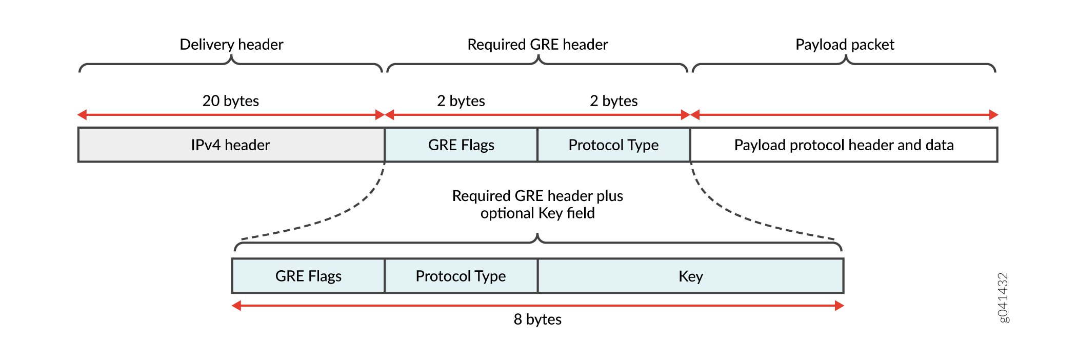
Filter-based tunneling encapsulates the original passenger protocol packet in an outer shell. For filter-based tunneling across IPv4 networks, the shell adds 24 bytes or 28 bytes of overhead, including 20 bytes of IPv4 header. Figure 2 shows the structure of a passenger protocol packet (the GRE payload) with a GRE header and IPv4 header attached.

As specified in RFC 1701, five GRE flag bits indicate whether a particular GRE header includes any optional fields (Checksum, Offset, Key, Sequence Number, and Routing). Of the five optional fields, filter-based GRE IPv4 tunneling uses the Key field only.
GRE Header Format
Figure 3 shows the format of the variable-size GRE header used for filter-based tunneling across IPv4 networks, with bit 0 the most significant bit and bit 15 the least significant bit.
The first two octets encode GRE flags, as described in Table 1.
The 2-octet Protocol Type field contains the value 0x0800 to specify the EtherType value for the IPv4 protocol.
The 4-octet Key field is included only if the Key Present bit is set to 1. The Key field carries the key value of the tunnel defined on the encapsulator. If the GRE tunnel definition specifies a key, the Packet Forwarding Engine for the encapsulating endpoint sets the Key Present bit and adds the Key to the GRE header.
|
Bit Offset and Field Name |
Transmitted Value for Filter-Based GRE Tunneling |
||
|---|---|---|---|
|
0 |
C = Checksum Present |
0 |
Checksum field is not used. |
|
1 |
R = Routing Present |
0 |
Offset and Routing fields are not used. |
|
2 |
K = Key Present |
0 or 1 |
Transmitted as 0 for a keyless tunnel or 1 for a keyed tunnel. |
|
3 |
S = Sequence Number Present |
0 |
Sequence Number field is not used. |
|
4 |
s = Strict Source Route |
0 |
Not all routing information is Strict Source Routes. |
|
5 - 7 |
Recur = Recursion Control information |
000 |
No additional encapsulations are permitted. |
|
8 - 12 |
Flags = Flag bits |
00000 |
Reserved. |
|
13 - 15 |
Ver = Version number |
000 |
Reserved. |
When the Packet Forwarding Engine performs encapsulation for a keyed GRE IPv4 tunnel, the process constructs the first two octets of the GRE header as 0x0000. When the Packet Forwarding Engine performs encapsulation for a non-keyed GRE IPv4 tunnel, the process constructs the first two octets of the GRE header as 0x2000.