Example: Setting Up a VXLAN Layer 2 Gateway and OVSDB Connections in a Contrail Environment (Trunk Interfaces That Support Untagged Packets)
In a physical network, a Juniper Networks switch that supports Virtual Extensible LAN (VXLAN) can function as a hardware virtual tunnel endpoint (VTEP). In this role, the Juniper Networks switch encapsulates in VXLAN packets Layer 2 Ethernet frames received from software applications that run directly on a physical server. The VXLAN packets are tunneled over a Layer 3 transport network. Upon receipt of the VXLAN packets, software VTEPs in the virtual network de-encapsulate the packets and forward them to virtual machines (VMs).
In this VXLAN environment, you can also include Contrail controllers and implement the Open vSwitch Database (OVSDB) management protocol on the Juniper Networks switch that functions as a hardware VTEP.
The Junos OS implementation of OVSDB provides a means through which Contrail controllers and Juniper Networks switches can exchange MAC addresses of entities in the physical and virtual networks. This exchange of MAC addresses enables the Juniper Networks switch that functions as a hardware VTEP to forward traffic to software VTEPs in the virtual network and software VTEPs in the virtual network to forward traffic to the Juniper Networks switch in the physical network.
This example explains how to configure a Juniper Networks switch as a hardware VTEP, which serves as a Layer 2 gateway, and set up this switch with an OVSDB connection to a Contrail controller.
In this example, only one VXLAN is deployed. Given this scenario, the packets exchanged between an application running on a physical server and a VM in the VXLAN are untagged. Therefore, in this example, a trunk interface is used for the connection between the physical server and the switch, as well as a native VLAN. The native VLAN enables the trunk interface to handle the untagged packets.
Requirements
This example includes the following hardware and software components:
A physical server on which software applications directly run.
A QFX10002 switch running Junos OS Release 15.1X53-D30 or later.
On the Juniper Networks switch, physical interface ge-1/0/0 provides a connection to physical server 1.
A Contrail controller.
Contrail Web user interface.
A vRouter that includes VMs managed by a hypervisor, which includes a software VTEP.
All components in the Contrail environment (Contrail controller, TSN, Contrail Web user interface, and vRouters must be running Contrail Release 2.20 or later.
For information about the Contrail components, see Using TOR Switches and OVSDB to Extend the Contrail Cluster to Other Instances..
Before you begin:
Create an SSL private key and certificate, if they do not already exist. The private key and certificate must be installed in the /var/db/certs directory of the Juniper Networks switch. See Creating and Installing an SSL Key and Certificate on a Juniper Networks Device for Connection with SDN Controllers
Overview and Topology
Figure 1 shows a topology in which a software application running directly on physical server 1 in the physical network needs to communicate with virtual machine VM 1 in VXLAN 1 and vice versa.
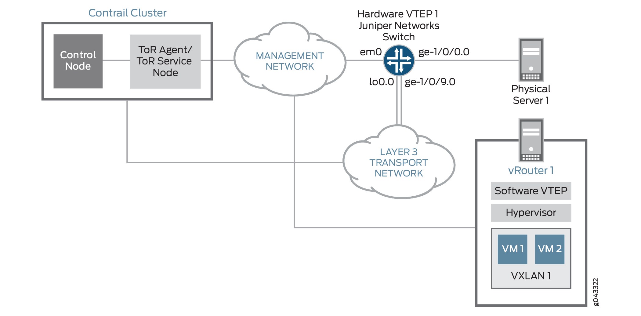
To establish communication between the software application on physical server 1 and VM 1 in VXLAN 1, a connection with a Contrail controller is configured on the management interface of the Juniper Networks switch.
Some entities in the OVSDB-VXLAN topology must be configured in both the Contrail Web user interface and on the Juniper Networks switch. Table 1 provides a summary of the entities that must be configured and where they must be configured.
The term used for an entity configured in the Contrail Web user interface can differ from the term used for essentially the same entity that is configured on the Juniper Networks switch. To prevent confusion, Table 1 shows the Contrail Web user interface and Junos OS entities side-by-side.
Entity |
Entity to Be Configured in the Contrail Web User Interface |
Entity to Be Configured on the Juniper Networks Switch |
|---|---|---|
VXLAN 1 |
Virtual network for VXLAN 1 |
VXLAN 1 Note:
The Juniper Networks switch dynamically configures this VXLAN. |
Physical interface (ge-1/0/0) between physical server 1 and Juniper Networks switch |
– |
OVSDB management. Specify that interface ge-1/0/0 is managed by OVSDB. |
One logical interface (ge-1/0/0.0) associated with VXLAN 1 |
One logical interface for VXLAN 1. For this interface, specify VLAN ID 0. Note:
A VLAN ID of 0 indicates that the interface must handle untagged packets. |
One logical interface (ge-1/0/0.0) for VXLAN 1. Note:
The Juniper Networks switch dynamically configures this logical interface. |
Juniper Networks switch (hardware VTEP 1) |
Physical router |
Hardware VTEP functionality. Configure the Juniper Networks switch to function as a hardware VTEP. |
In the Contrail Web user interface, a virtual network is configured. In this configuration, a VXLAN identifier of 100 is specified. Also, the universally unique identifier (UUID) assigned to the virtual network is Contrail-28805c1d-0122-495d-85df-19abd647d772. Based on this configuration, the Juniper Networks switch dynamically creates the following configuration for a Junos OS-equivalent VXLAN:
set vlans Contrail-28805c1d-0122-495d-85df-19abd647d772 vxlan vni 100
Based on the logical interface configuration (VLAN number 0) in the Contrail Web user interface, the Juniper Networks switch dynamically creates the following configuration for a Junos OS-equivalent interface:
set interfaces ge-1/0/0 flexible-vlan-tagging
set interfaces ge-1/0/0 native-vlan-id 4094
set interfaces ge-1/0/0 encapsulation extended-vlan-bridge
set interfaces ge-1/0/0 unit 0 vlan-id 4094
set vlans Contrail-28805c1d-0122-495d-85df-19abd647d772 interface ge-1/0/0.0
This sample configuration does the following:
Configures physical interface ge-1/0/0 as a Layer 2 trunk interface.
Creates a native VLAN with an ID of 4094.
Creates logical interface ge-1/0/0.0, and specifies that it is a member of the native VLAN.
Associates logical interface ge-1/0/0.0 with VXLAN Contrail-28805c1d-0122-495d-85df-19abd647d772.
As a result of the above configuration, logical interface ge-1/0/0.0 handles incoming untagged packets.
Table 2 provides a summary of the VXLAN-OVSDB topology components that are configured on the Juniper Networks switch and the configuration settings for each component.
Topology
Component |
Setting |
|---|---|
Contrail controller |
IP address: 10.94.184.1 |
OVSDB-managed physical interface |
Interface name: ge-1/0/0 Native VLAN ID: 4094 |
VXLAN 1 and associated logical interface |
Note:
The Juniper Networks switch dynamically configures the VXLAN and associated logical interface, which are based on the virtual network and associated logical interface configurations in the Contrail Web user interface. Therefore, no manual configuration is required. VXLAN name: Contrail-28805c1d-0122-495d-85df-19abd647d772 VNI: 100 Logical interface name: ge-1/0/0.0 Interface type: trunk Member of native VLAN 4094 Associated with VXLAN Contrail-28805c1d-0122-495d-85df-19abd647d772 |
OVSDB tracing operations |
Filename: /var/log/ovsdb File size: 10 MB Flag: All |
Hardware VTEP |
Hostname: hw-vtep1 Source interface: loopback (lo0.0) Source IP address: 10.17.17.17/32 |
Handling of Layer 2 BUM traffic in VXLAN Contrail-28805c1d-0122-495d-85df-19abd647d772 |
TSN Note:
By default, one or more TSNs handle Layer 2 BUM traffic within a VXLAN; therefore, no manual configuration is required. |
Non-OVSDB and Non-VXLAN Configuration
CLI Quick Configuration
To quickly configure this example, copy the
following commands, paste them into a text file, remove any line breaks,
change any details necessary to match your configuration, copy and
paste the commands into the CLI at the [edit] hierarchy
level, and then enter commit from configuration mode.
set interfaces ge-1/0/9 unit 0 family inet address 10.40.40.1/24
set routing-options static route 10.19.19.19/32 next-hop 10.40.40.2
set routing-options router-id 10.17.17.17
set protocols ospf area 0.0.0.0 interface lo0.0
set protocols ospf area 0.0.0.0 interface ge-1/0/9.0
Procedure
Step-by-Step Procedure
To configure the Layer 3 network over which the packets exchanged between physical server 1 and VM 1 are tunneled:
Configure the Layer 3 interface.
[edit interfaces]
user@switch# set ge-1/0/9 unit 0 family inet address 10.40.40.1/24
Set the routing options.
[edit routing-options]
user@switch# set static route 10.19.19.19/32 next-hop 10.40.40.2
user@switch# set router-id 10.17.17.17
Configure the routing protocol.
[edit protocols]
user@switch# set ospf area 0.0.0.0 interface lo0.0
user@switch# set ospf area 0.0.0.0 interface ge-1/0/9.0
OVSDB and VXLAN Configuration
CLI Quick Configuration
To quickly configure this example, copy the
following commands, paste them into a text file, remove any line breaks,
change any details necessary to match your configuration, copy and
paste the commands into the CLI at the [edit] hierarchy
level, and then enter commit from configuration mode.
set system host-name hw-vtep1
set switch-options ovsdb-managed
set protocols ovsdb controller 10.94.184.1
set protocols ovsdb interfaces ge-1/0/0
set protocols ovsdb traceoptions file ovsdb
set protocols ovsdb traceoptions file size 10m
set protocols ovsdb traceoptions flag all
set interfaces lo0 unit 0 family inet address 10.17.17.17/32 primary
set interfaces lo0 unit 0 family inet address 10.17.17.17/32 preferred
set switch-options vtep-source-interface lo0.0
Procedure
Step-by-Step Procedure
To configure the Juniper Networks switch as a hardware VTEP with an OVSDB connection to a Contrail controller:
Configure a unique hostname for the Juniper Networks switch.
[edit system]
user@switch# set host-name hw-vtep1
Enable the Juniper Networks switch to dynamically configure OVSDB-managed VXLANs and associated interfaces.
[edit switch-options]
user@switch# ovsdb-managed
Configure a connection with a Contrail controller.
[edit protocols]
user@switch# set ovsdb controller  10.94.184.1
Specify that the interface between hardware VTEP 1 and physical server 1 is managed by OVSDB.
[edit protocols]
user@switch# set ovsdb interfaces ge-1/0/0
Set up OVSDB tracing operations.
[edit protocols]
user@switch# set ovsdb traceoptions file ovsdb
user@switch# set ovsdb traceoptions file size 10m
user@switch# set ovsdb traceoptions flag all
Specify an IP address for the loopback interface. This IP address serves as the source IP address in the outer header of any VXLAN-encapsulated packet.
[edit interfaces]
user@switch# set lo0 unit 0 family inet address 10.17.17.17/32 primary
user@switch# set lo0 unit 0 family inet address 10.17.17.17/32 preferred
-
Set the loopback interface as the interface that identifies hardware VTEP 1.
[edit switch-options]
user@switch# set vtep-source-interface lo0.0
In the Contrail Web user interface, configure a virtual network for VXLAN 1. See Contrail Configuration for Juniper Networks Devices That Function as Hardware VTEPs.
In the Contrail Web user interface, configure a logical interface for the virtual network that you created in step 6. See Contrail Configuration for Juniper Networks Devices That Function as Hardware VTEPs.
In the Contrail Web user interface, configure a physical router, which enables the Contrail controller to recognize the Juniper Networks switch as a VTEP. See Contrail Configuration for Juniper Networks Devices That Function as Hardware VTEPs.
Verification
Confirm that the configuration is working properly:
- Verifying the Logical Switch Configuration
- Verifying the MAC Address of VM 1
- Verifying the Contrail Controller Connection
- Verifying the OVSDB-Managed Interface
Verifying the Logical Switch Configuration
Purpose
In the Contrail Web user interface, you configured
a virtual network for VXLAN 1. Using the same terminology as in the
OVSDB schema for physical devices, the virtual network is also known
as a logical switch. Verify that the configuration
of the logical switch with the UUID of Contrail-28805c1d-0122-495d-85df-19abd647d772
is present in the OVSDB schema and that the Flags field for the logical
switch is Created by both.
Action
From the operational mode, enter the show ovsdb
logical-switch command.
user@switch> show ovsdb logical-switch
Logical switch information:
Logical Switch Name: Contrail-28805c1d-0122-495d-85df-19abd647d772
Flags: Created by both
VNI: 100
Num of Remote MAC: 1
Num of Local MAC: 0
Meaning
The output verifies that the configuration for the
logical switch is present. The Created by both state indicates
that the virtual network was configured in the Contrail Web user interface,
and that the Juniper Networks switch dynamically created the corresponding
VXLAN. In this state, the virtual network and the VXLAN are operational.
If the state of the logical switch is something other than Created by both, see Troubleshooting a Nonoperational Logical Switch and Corresponding Junos OS OVSDB-Managed VXLAN.
Verifying the MAC Address of VM 1
Purpose
Verify that the MAC address of VM 1 is present in the OVSDB schema.
Action
From operational mode, enter the show ovsdb mac
remote command.
user@switch> show ovsdb mac remote
Logical Switch Name: Contrail-28805c1d-0122-495d-85df-19abd647d772
  Mac                    IP                 Encapsulation      Vtep
  Address                Address                               Address
  a8:59:5e:f6:38:90      0.0.0.0            Vxlan over Ipv4    10.17.17.17
Meaning
The output shows that the MAC address for VM 1 is present and is associated with the logical switch with the UUID of Contrail-28805c1d-0122-495d-85df-19abd647d772. Given that the MAC address is present, VM 1 is reachable through the Juniper Networks switch, which functions as a hardware VTEP.
Verifying the Contrail Controller Connection
Purpose
Verify that the connection with the Contrail controller is up.
Action
From operational mode, enter the show ovsdb controller command to verify that the Contrail controller connection state
is up.
user@switch> show ovsdb controller
VTEP controller information:
Controller IP address: 10.94.184.1
Controller protocol: ssl
Controller port: 6632
Controller connection: up
Controller seconds-since-connect: 542325
Controller seconds-since-disconnect: 542346
Controller connection status: active
Meaning
The output shows that the state of the connection is up, in addition to other information about the connection.
The up state indicates that OVSDB is enabled on the Juniper
Networks switch.
Verifying the OVSDB-Managed Interface
Purpose
Verify that interface ge-1/0/0.0 is managed by OVSDB.
Action
From operational mode, enter the show ovsdb interface command to verify that interface ge-1/0/0.0 is managed by OVSDB.
user@switch> show ovsdb interface
Interface  VLAN ID Bridge-domain
ge-1/0/0   0       Contrail-28805c1d-0122-495d-85df-19abd647d772
Meaning
The output shows that interface ge-1/0/0 is managed by OVSDB. It also indicates that the interface is associated with VXLAN Contrail-28805c1d-0122-495d-85df-19abd647d772, which has a VLAN ID of 0.