ON THIS PAGE
Excluding an OSPF Interface as a Backup for a Protected Interface
Configuring Backup SPF Options for Protected OSPF Interfaces
Configuring RSVP Label-Switched Paths as Backup Paths for OSPF
Configuring Remote LFA Backup over LDP Tunnels in an OSPF Network
Example: Configuring Remote LFA Over LDP Tunnels in OSPF Networks
Configuring Loop-Free Alternate Routes for OSPF
Per Prefix Loop Free Alternates for OSPF
In certain topologies and usage scenarios, when multiple destinations originate the same prefix and there is no viable LFA to the best prefix originator, whilst a non-best prefix originator has one. Per-prefix LFA is a technology by which, the LFA to a non-best prefix originator can be used in lieu of the LFA to the best prefix originator to provide local repair. This can be used to increase the local repair coverage for the OSPF protocol also.
Per-Prefix Loop Free Alternates (LFA)—Loop Free Alternates (LFA) is a technology by which a neighbor can be used as a backup next hop to provide a local repair path for the traffic to flow temporarily in case of failures in the primary next hop (node or link). For this, the basic requirement is that the selected backup neighbor provides a loop free path with respect to primary next hop towards a destination, originating a set of interior gateway protocol (IGP) prefixes.
The following topology explains the deployment case where per prefix LFA feature is applicable.
ABR1 and ABR2 are area boundary routers (ABRs), dual homed to an IPv6 core network, which advertises the summary LSA for the prefix 10.0.1.0/24 with a metric of 10. Also, from PE router’s perspective, ABR1 is the best prefix originator for 10.0.1.0/24. In this case, P2 is not a valid LFA for ABR1 because of the equal cost multi paths (ECMP) {P2, PE, P1, ABR1} and {P2, ABR2, ABR1} causing some of the traffic to be looped back through the router PE (no valid LFA). However for ABR2, which is also a prefix originator for 10.0.1.0/24, P2 is a valid LFA because the only path is {P2, ABR2}.
Configuring Per-Prefix LFA for OSPF
Per prefix LFA is a mechanism by which LFA to a non-best prefix originator can be used in lieu of the LFA to the best prefix originator to provide local repair. In such cases, per prefix LFA can be used to increase the local repair coverage for the OSPF protocol.
Loop Free Alternates (LFA) is a mechanism by which a neighbor can be used as a backup next hop to provide a local repair path for the traffic to flow temporarily in case of failures in the primary next hop (node or link). For this the basic requirement is that the selected backup neighbor provides a loop free path with respect to primary next hop towards a destination originating a set of IGP prefixes. In certain topologies and usage scenarios, it may be possible that multiple destinations are originating the same prefix and there is no viable LFA to the best prefix originator, whilst a non-best prefix originator has one. Per prefix LFA is a mechanism by which LFA to a non-best prefix originator can be used in lieu of the LFA to the best prefix originator to provide local repair. In such cases, per prefix LFA can be used to increase the local repair coverage for the OSPF protocol.
To configure per prefix LFA for an OSPF interface:
per-prefix-calculation configuration
statement at the [edit protocols (ospf | ospf3) backup-spf-options] hierarchy level.Loop-Free Alternate Routes for OSPF Overview
Support for OSPF loop-free alternate routes essentially adds IP fast-reroute capability for OSPF. Junos OS precomputes loop-free backup routes for all OSPF routes. These backup routes are preinstalled in the Packet Forwarding Engine, which performs a local repair and implements the backup path when the link for a primary next hop for a particular route is no longer available. With local repair, the Packet Forwarding Engine can correct a path failure before it receives precomputed paths from the Routing Engine. Local repair reduces the amount of time needed to reroute traffic to less than 50 milliseconds. In contrast, global repair can take up to 800 milliseconds to compute a new route. Local repair enables traffic to continue to be routed using a backup path until global repair is able to calculate a new route.
A loop-free path is one that does not forward traffic back through the routing device to reach a given destination. That is, a neighbor whose shortest path first to the destination traverses the routing device that is not used as a backup route to that destination. To determine loop-free alternate paths for OSPF routes, Junos OS runs shortest-path-first (SPF) calculations on each one-hop neighbor. You can enable support for alternate loop-free routes on any OSPF interface. Because it is common practice to enable LDP on an interface for which OSPF is already enabled, this feature also provides support for LDP label-switched paths (LSPs.)
If you enable support for alternate loop-free routes on
an interface configured for both LDP and OSPF, you can use the traceroute command to trace the active path to the primary
next hop.
The level of backup coverage available through OSPF routes depends on the actual network topology and is typically less than 100 percent for all destinations on any given routing device. You can extend backup coverage to include RSVP LSP paths.
Junos OS provides three mechanisms for route redundancy for OSPF through alternate loop-free routes:
Link protection—Offers per-link traffic protection. Use link protection when you assume that only a single link might become unavailable but that the neighboring node on the primary path would still be available through another interface.
Node-link protection—Establishes an alternate path through a different routing device altogether. Use node-link protection when you assume that access to a node is lost when a link is no longer available. As a result, Junos OS calculates a backup path that avoids the primary next-hop routing device.
Per-prefix loop-free alternates (LFAs)—It is a technology by which a neighbor can be used as a backup next hop to provide a local repair path for the traffic to flow temporarily in case of failures in the primary next hop (node or link). For this, the basic requirement is that the selected backup neighbor provides a loop-free path with respect to a primary next hop towards a destination, originating a set of interior gateway protocol (IGP) prefixes.
In certain topologies and usage scenarios, it may be possible that multiple destinations are originating the same prefix and there is no viable LFA to the best prefix originator, while a non-best prefix originator has a viable LFA. Per-prefix LFA is a mechanism by which LFA to a non-best prefix originator can be used in lieu of the LFA to the best prefix originator to provide local repair. In such cases, per prefix LFA can be used to increase the local repair coverage for the OSPF protocol.
When you enable link protection or node-link protection on an OSPF interface, Junos OS creates an alternate path to the primary next hop for all destination routes that traverse a protected interface.
Example: Configuring Loop-Free Alternate Routes for OSPF
This example demonstrates the use of link protection for interfaces that have OSPF enabled.
When you enable link protection, Junos OS creates an alternate path to the primary next hop for all destination routes that traverse a protected interface. Use link protection when you assume that only a single link might become unavailable but that the neighboring node would still be available through another interface.
Requirements
No special configuration beyond device initialization is required before configuring this example.
Overview
In this example, six OSPF neighbors are configured with link protection. This causes Junos OS to create an alternate path to the primary next hop for all destination routes that traverse each protected interface. Link protection is used here because even if a link becomes unavailable, the neighboring node would still be available through another interface.
The example shows two topologies. One is the default topology, and the other is the voice topology. For more information about multitopology routing, see the Multitopology Routing User Guide.
The example also includes RSVP LSPs configured as backup LSPs for protected OSPF interfaces.
Topology
Figure 2 shows the sample network.
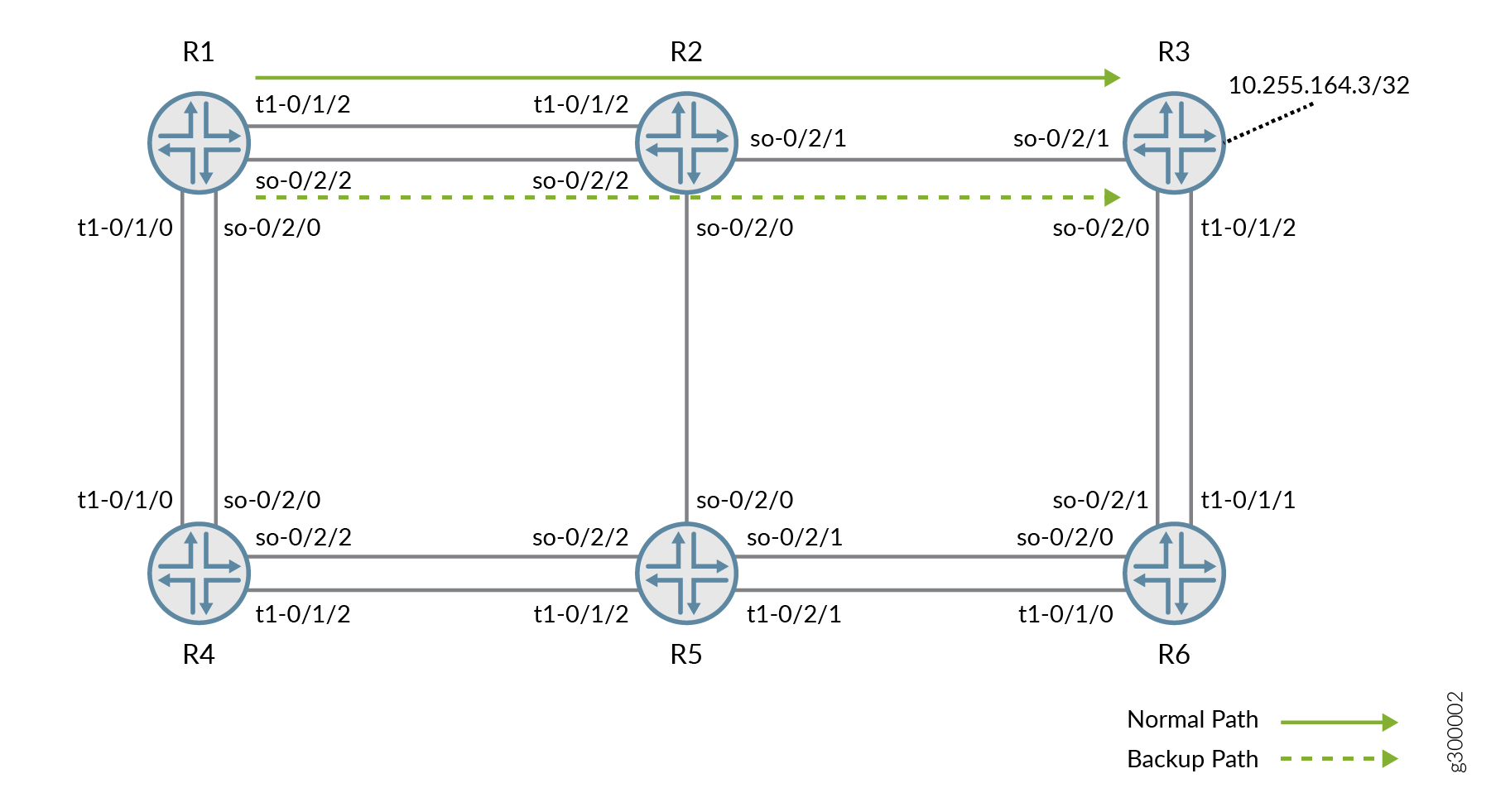
CLI Quick Configuration shows the configuration for all of the devices in Figure 2.
The section #d150e111__d150e873 describes the steps on Device R1.
Configuration
CLI Quick Configuration
To quickly configure this
example, copy the following commands, paste them into a text file,
remove any line breaks, change any details necessary to match your
network configuration, and then copy and paste the commands into the
CLI at the [edit] hierarchy level.
Device R1
               set interfaces so-0/2/2 unit 0 description to-R2


               set interfaces so-0/2/2 unit 0 family inet address 192.168.242.1/30


               set interfaces so-0/2/2 unit 0 family mpls


               set interfaces t1-0/1/2 unit 0 description to-R2


               set interfaces t1-0/1/2 unit 0 family inet address 192.168.241.1/30


               set interfaces t1-0/1/2 unit 0 family mpls


               set interfaces t1-0/1/0 unit 0 description to-R4


               set interfaces t1-0/1/0 unit 0 family inet address 192.168.241.17/30


               set interfaces t1-0/1/0 unit 0 family mpls


               set interfaces so-0/2/0 unit 0 description to-R4


               set interfaces so-0/2/0 unit 0 family inet address 192.168.242.17/30


               set interfaces so-0/2/0 unit 0 family mpls


               set interfaces lo0 unit 0 family inet address 10.255.164.1/32 primary


               set protocols rsvp interface all link-protection


               set protocols rsvp interface fxp0.0 disable


               set protocols mpls label-switched-path path1 backup


               set protocols mpls label-switched-path path1 to 10.255.164.3


               set protocols mpls label-switched-path path2 backup


               set protocols mpls label-switched-path path2 to 10.255.164.3


               set protocols mpls interface all


               set protocols mpls interface fxp0.0 disable


               set protocols ospf topology voice topology-id 32


               set protocols ospf traffic-engineering


               set protocols ospf area 0.0.0.0 interface fxp0.0 disable


               set protocols ospf area 0.0.0.0 interface lo0.0 passive


               set protocols ospf area 0.0.0.0 interface so-0/2/0.0 link-protection


               set protocols ospf area 0.0.0.0 interface so-0/2/0.0 metric 10


               set protocols ospf area 0.0.0.0 interface so-0/2/2.0 link-protection


               set protocols ospf area 0.0.0.0 interface so-0/2/2.0 metric 10


               set protocols ospf area 0.0.0.0 interface t1-0/1/0.0 link-protection


               set protocols ospf area 0.0.0.0 interface t1-0/1/0.0 metric 10


               set protocols ospf area 0.0.0.0 interface t1-0/1/2.0 link-protection


               set protocols ospf area 0.0.0.0 interface t1-0/1/2.0 metric 10


               set protocols ldp interface all


               set protocols ldp interface fxp0.0 disable


               set policy-options policy-statement pplb then load-balance per-packet


               set routing-options forwarding-table export pplb


               set routing-options topologies family inet topology voice


               set routing-options forwarding-table indirect-next-hop-change-acknowledgements
Device R2
               set interfaces so-0/2/2 unit 0 description to-R1


               set interfaces so-0/2/2 unit 0 family inet address 192.168.242.2/30


               set interfaces so-0/2/2 unit 0 family mpls


               set interfaces t1-0/1/2 unit 0 description to-R1


               set interfaces t1-0/1/2 unit 0 family inet address 192.168.241.2/30


               set interfaces t1-0/1/2 unit 0 family mpls


               set interfaces so-0/2/0 unit 0 description to-R5


               set interfaces so-0/2/0 unit 0 family inet address 192.168.242.21/30


               set interfaces so-0/2/0 unit 0 family mpls


               set interfaces so-0/2/1 unit 0 description to-R3


               set interfaces so-0/2/1 unit 0 family inet address 192.168.242.5/30


               set interfaces so-0/2/1 unit 0 family mpls


               set interfaces lo0 unit 0 family inet address 10.255.164.2/32 primary


               set protocols rsvp interface all link-protection


               set protocols rsvp interface fxp0.0 disable


               set protocols mpls interface all


               set protocols mpls interface fxp0.0 disable


               set protocols ospf topology voice topology-id 32


               set protocols ospf traffic-engineering


               set protocols ospf area 0.0.0.0 interface fxp0.0 disable


               set protocols ospf area 0.0.0.0 interface lo0.0 passive


               set protocols ospf area 0.0.0.0 interface so-0/2/2.0 link-protection


               set protocols ospf area 0.0.0.0 interface so-0/2/2.0 metric 10


               set protocols ospf area 0.0.0.0 interface so-0/2/0.0 link-protection


               set protocols ospf area 0.0.0.0 interface so-0/2/0.0 metric 10


               set protocols ospf area 0.0.0.0 interface t1-0/1/2.0 link-protection


               set protocols ospf area 0.0.0.0 interface t1-0/1/2.0 metric 10


               set protocols ospf area 0.0.0.0 interface so-0/2/1.0 link-protection


               set protocols ospf area 0.0.0.0 interface so-0/2/1.0 metric 10


               set protocols ldp interface all


               set protocols ldp interface fxp0.0 disable


               set routing-options topologies family inet topology voice


               set routing-options forwarding-table indirect-next-hop-change-acknowledgements
Device R3
               set interfaces t1-0/1/2 unit 0 description to-R6


               set interfaces t1-0/1/2 unit 0 family inet address 192.168.241.25/30


               set interfaces t1-0/1/2 unit 0 family mpls


               set interfaces so-0/2/1 unit 0 description to-R2


               set interfaces so-0/2/1 unit 0 family inet address 192.168.242.6/30


               set interfaces so-0/2/1 unit 0 family mpls


               set interfaces so-0/2/0 unit 0 description to-R6


               set interfaces so-0/2/0 unit 0 family inet address 192.168.242.25/30


               set interfaces so-0/2/0 unit 0 family mpls


               set interfaces lo0 unit 0 family inet address 10.255.164.3/32 primary


               set protocols rsvp interface all link-protection


               set protocols rsvp interface fxp0.0 disable


               set protocols mpls interface all


               set protocols mpls interface fxp0.0 disable


               set protocols ospf traceoptions file ospf


               set protocols ospf traceoptions file size 5m


               set protocols ospf traceoptions file world-readable


               set protocols ospf traceoptions flag error


               set protocols ospf topology voice topology-id 32


               set protocols ospf traffic-engineering


               set protocols ospf area 0.0.0.0 interface fxp0.0 disable


               set protocols ospf area 0.0.0.0 interface lo0.0 passive


               set protocols ospf area 0.0.0.0 interface so-0/2/0.0 link-protection


               set protocols ospf area 0.0.0.0 interface so-0/2/0.0 metric 5


               set protocols ospf area 0.0.0.0 interface t1-0/1/2.0 link-protection


               set protocols ospf area 0.0.0.0 interface t1-0/1/2.0 metric 10


               set protocols ospf area 0.0.0.0 interface so-0/2/1.0 link-protection


               set protocols ospf area 0.0.0.0 interface so-0/2/1.0 metric 10


               set protocols ldp interface all


               set protocols ldp interface fxp0.0 disable


               set routing-options static route 11.3.1.0/24 discard


               set routing-options static route 11.3.2.0/24 discard


               set routing-options static route 11.3.3.0/24 discard


               set routing-options topologies family inet topology voice


               set routing-options forwarding-table indirect-next-hop-change-acknowledgements
Device R4
               set interfaces t1-0/1/0 unit 0 description to-R1


               set interfaces t1-0/1/0 unit 0 family inet address 192.168.241.18/30


               set interfaces t1-0/1/0 unit 0 family mpls


               set interfaces so-0/2/0 unit 0 description to-R1


               set interfaces so-0/2/0 unit 0 family inet address 192.168.242.18/30


               set interfaces so-0/2/0 unit 0 family mpls


               set interfaces t1-0/1/2 unit 0 description to-R5


               set interfaces t1-0/1/2 unit 0 family inet address 192.168.241.9/30


               set interfaces t1-0/1/2 unit 0 family mpls


               set interfaces so-0/2/2 unit 0 description to-R5


               set interfaces so-0/2/2 unit 0 family inet address 192.168.242.9/30


               set interfaces so-0/2/2 unit 0 family mpls


               set interfaces lo0 unit 0 family inet address 10.255.164.4/32 primary


               set protocols rsvp interface all link-protection


               set protocols rsvp interface fxp0.0 disable


               set protocols mpls interface all


               set protocols mpls interface fxp0.0 disable


               set protocols ospf topology voice topology-id 32


               set protocols ospf traffic-engineering


               set protocols ospf area 0.0.0.0 interface fxp0.0 disable


               set protocols ospf area 0.0.0.0 interface lo0.0 passive


               set protocols ospf area 0.0.0.0 interface t1-0/1/0.0 link-protection


               set protocols ospf area 0.0.0.0 interface t1-0/1/0.0 metric 10


               set protocols ospf area 0.0.0.0 interface so-0/2/0.0 link-protection


               set protocols ospf area 0.0.0.0 interface so-0/2/0.0 metric 10


               set protocols ospf area 0.0.0.0 interface t1-0/1/2.0 link-protection


               set protocols ospf area 0.0.0.0 interface t1-0/1/2.0 metric 10


               set protocols ospf area 0.0.0.0 interface so-0/2/2.0 link-protection


               set protocols ospf area 0.0.0.0 interface so-0/2/2.0 metric 10


               set protocols ldp interface all


               set protocols ldp interface fxp0.0 disable


               set routing-options topologies family inet topology voice


               set routing-options forwarding-table indirect-next-hop-change-acknowledgements
Device R5
               set interfaces t1-0/1/2 unit 0 description to-R4


               set interfaces t1-0/1/2 unit 0 family inet address 192.168.241.10/30


               set interfaces t1-0/1/2 unit 0 family mpls


               set interfaces s0-0/2/0 unit 0 description to-R2


               set interfaces s0-0/2/0 unit 0 family inet address 192.168.242.22/30


               set interfaces s0-0/2/0 unit 0 family mpls


               set interfaces so-0/2/2 unit 0 description to-R4


               set interfaces so-0/2/2 unit 0 family inet address 192.168.242.10/30


               set interfaces so-0/2/2 unit 0 family mpls


               set interfaces so-0/2/1 unit 0 description to-R6


               set interfaces so-0/2/1 unit 0 family inet address 192.168.242.13/30


               set interfaces so-0/2/1 unit 0 family mpls


               set interfaces t1-0/2/1 unit 0 description to-R6


               set interfaces t1-0/2/1 unit 0 family inet address 192.168.241.13/30


               set interfaces t1-0/2/1 unit 0 family mpls


               set interfaces lo0 unit 0 family inet address 10.255.164.5/32 primary


               set protocols rsvp interface all link-protection


               set protocols rsvp interface fxp0.0 disable


               set protocols mpls interface all


               set protocols mpls interface fxp0.0 disable


               set protocols ospf topology voice topology-id 32


               set protocols ospf traffic-engineering


               set protocols ospf area 0.0.0.0 interface fxp0.0 disable


               set protocols ospf area 0.0.0.0 interface lo0.0 passive


               set protocols ospf area 0.0.0.0 interface so-0/2/1.0 link-protection


               set protocols ospf area 0.0.0.0 interface so-0/2/1.0 metric 5


               set protocols ospf area 0.0.0.0 interface t1-0/1/2.0 link-protection


               set protocols ospf area 0.0.0.0 interface t1-0/1/2.0 metric 10


               set protocols ospf area 0.0.0.0 interface s0-0/2/0.0 link-protection


               set protocols ospf area 0.0.0.0 interface s0-0/2/0.0 metric 10


               set protocols ospf area 0.0.0.0 interface so-0/2/2.0 link-protection


               set protocols ospf area 0.0.0.0 interface so-0/2/2.0 metric 10


               set protocols ospf area 0.0.0.0 interface t1-0/2/1.0 link-protection


               set protocols ospf area 0.0.0.0 interface t1-0/2/1.0 metric 10


               set protocols ldp interface all


               set protocols ldp interface fxp0.0 disable


               set routing-options topologies family inet topology voice


               set routing-options forwarding-table indirect-next-hop-change-acknowledgements
Device R6
               set interfaces so-0/2/0 unit 0 description to-R5


               set interfaces so-0/2/0 unit 0 family inet address 192.168.242.14/30


               set interfaces so-0/2/0 unit 0 family mpls


               set interfaces t1-0/1/0 unit 0 description to-R5


               set interfaces t1-0/1/0 unit 0 family inet address 192.168.241.14/30


               set interfaces t1-0/1/0 unit 0 family mpls


               set interfaces t1-0/1/1 unit 0 description to-R3


               set interfaces t1-0/1/1 unit 0 family inet address 192.168.241.26/30


               set interfaces t1-0/1/1 unit 0 family mpls


               set interfaces so-0/2/1 unit 0 description to-R3


               set interfaces so-0/2/1 unit 0 family inet address 192.168.242.26/30


               set interfaces so-0/2/1 unit 0 family mpls


               set interfaces lo0 unit 0 family inet address 10.255.164.6/32 primary


               set protocols rsvp interface all link-protection


               set protocols rsvp interface fxp0.0 disable


               set protocols mpls interface all


               set protocols mpls interface fxp0.0 disable


               set protocols ospf topology voice topology-id 32


               set protocols ospf traffic-engineering


               set protocols ospf area 0.0.0.0 interface fxp0.0 disable


               set protocols ospf area 0.0.0.0 interface lo0.0 passive


               set protocols ospf area 0.0.0.0 interface so-0/2/1.0 link-protection


               set protocols ospf area 0.0.0.0 interface so-0/2/1.0 metric 5


               set protocols ospf area 0.0.0.0 interface so-0/2/0.0 link-protection


               set protocols ospf area 0.0.0.0 interface so-0/2/0.0 metric 5


               set protocols ospf area 0.0.0.0 interface t1-0/1/0.0 link-protection


               set protocols ospf area 0.0.0.0 interface t1-0/1/0.0 metric 10


               set protocols ospf area 0.0.0.0 interface t1-0/1/1.0 link-protection


               set protocols ospf area 0.0.0.0 interface t1-0/1/1.0 metric 10


               set protocols ldp interface all


               set protocols ldp interface fxp0.0 disable


               set routing-options topologies family inet topology voice


               set routing-options forwarding-table indirect-next-hop-change-acknowledgements
Procedure
Step-by-Step Procedure
The following example requires that you navigate various levels in the configuration hierarchy. For information about navigating the CLI, see Using the CLI Editor in Configuration Mode in the CLI User Guide.
To configure Device R1:
-
Configure the device interfaces.
[edit interfaces] user@R1# set so-0/2/2 unit 0 description to-R2 user@R1# set so-0/2/2 unit 0 family inet address 192.168.242.1/30 user@R1# set so-0/2/2 unit 0 family mpls user@R1# set t1-0/1/2 unit 0 description to-R2 user@R1# set t1-0/1/2 unit 0 family inet address 192.168.241.1/30 user@R1# set t1-0/1/2 unit 0 family mpls user@R1# set t1-0/1/0 unit 0 description to-R4 user@R1# set t1-0/1/0 unit 0 family inet address 192.168.241.17/30 user@R1# set t1-0/1/0 unit 0 family mpls user@R1# set so-0/2/0 unit 0 description to-R4 user@R1# set so-0/2/0 unit 0 family inet address 192.168.242.17/30 user@R1# set so-0/2/0 unit 0 family mpls user@R1# set lo0 unit 0 family inet address 10.255.164.1/32 primary -
Extend backup coverage to include RSVP LSP paths.
[edit protocols rsvp] user@R1# set interface all link-protection user@R1# set interface fxp0.0 disable -
Enable MPLS on the interfaces, and configure backup LSPs to Device R3.
[edit protocols mpls] user@R1# set interface all user@R1# set interface fxp0.0 disable user@R1# set label-switched-path path1 backup user@R1# set label-switched-path path1 to 10.255.164.3 user@R1# set label-switched-path path2 backup user@R1# set label-switched-path path2 to 10.255.164.3 -
Configure OSPF connections, link metrics, and link protection.
[edit protocols ospf] user@R1# set traffic-engineering [edit protocols ospf area 0.0.0.0] user@R1# set interface fxp0.0 disable user@R1# set interface lo0.0 passive user@R1# set interface so-0/2/0.0 link-protection user@R1# set interface so-0/2/0.0 metric 10 user@R1# set interface so-0/2/2.0 link-protection user@R1# set interface so-0/2/2.0 metric 10 user@R1# set interface t1-0/1/0.0 link-protection user@R1# set interface t1-0/1/0.0 metric 10 user@R1# set interface t1-0/1/2.0 link-protection user@R1# set interface t1-0/1/2.0 metric 10 -
(Optional) Configure a specific OSPF topology for voice traffic.
[edit protocols ospf] user@R1# set topology voice topology-id 32 [edit routing-options topologies family inet] user@R1# set topology voice -
Enable LDP on the interfaces.
[edit protocols ldp] user@R1# set interface all user@R1# set interface fxp0.0 disable -
(Optional) Configure per-packet load balancing.
[edit policy-options policy-statement pplb] user@R1# set then load-balance per-packet [edit routing-options forwarding-table] user@R1# set export pplb -
Configure the routing protocol process (rpd) to request an acknowledgement when creating a new forwarding next hop.
We recommend that the
indirect-next-hop-change-acknowledgementsstatement be configured when protection mechanisms are being used. This includes MPLS RSVP protection such as fast reroute (FRR) as well as interior gateway protocol (IGP) loop-free alternate (LFA) link or node protection.[edit routing-options forwarding-table] user@R1# set indirect-next-hop-change-acknowledgements
Results
From configuration mode, confirm your configuration
by entering the show interfaces, show protocols, show policy-options, and show routing-options commands. If the output does not display the intended configuration,
repeat the instructions in this example to correct the configuration.
user@R1# show interfaces
so-0/2/2 {
    unit 0 {
        description to-R2;
        family inet {
            address 192.168.242.1/30;
        }
        family mpls;
    }
}
t1-0/1/2 {
    unit 0 {
        description to-R2;
        family inet {
            address 192.168.241.1/30;
        }
        family mpls;
    }
}
t1-0/1/0 {
    unit 05 {
        description to-R4;
        family inet {
            address 192.168.241.17/30;
        }
        family mpls;
    }
}
so-0/2/0 {
    unit 0 {
        description to-R4;
        family inet {
            address 192.168.242.17/30;
        }
        family mpls;
    }
}
lo0 {
    unit 0 {
        family inet {
            address 10.255.164.1/32 {
                primary;
            }
        }
    }
}
user@R1# show protocols
rsvp {
    interface all {
        link-protection;
    }
    interface fxp0.0 {
        disable;
    }
}
mpls {
    label-switched-path path1 {
        backup;
        to 10.255.164.3;
    }
    label-switched-path path2 {
        backup;
        to 10.255.164.3;
    }
    interface all;
    interface fxp0.0 {
        disable;
    }
}
ospf {
    topology voice topology-id 32;
    traffic-engineering;
    area 0.0.0.0 {
        interface fxp0.0 {
            disable;
        }
        interface lo0.0 {
            passive;
        }
        interface so-0/2/0.0 {
            link-protection;
            metric 10;
        }
        interface so-0/2/2.0 {
            link-protection;
            metric 10;
        }
        interface t1-0/1/0.0 {
            link-protection;
            metric 10;
        }
        interface t1-0/1/2.0 {
            link-protection;
            metric 10;
        }
    }
}
ldp {
    interface all;
    interface fxp0.0 {
        disable;
    }
}
user@R1# show policy-options
policy-statement pplb {
    then {
        load-balance per-packet;
    }
}
user@R1# show routing-options
forwarding-table {
    export pplb;
    indirect-next-hop-change-acknowledgements;
}
topologies {
    family inet {
        topology voice;
    }
}
If you are done configuring the device, enter commit from configuration mode.
Verification
Confirm that the configuration is working properly.
- Verifying the Routes on Device R1
- Checking the Backup Coverage
- Checking the Backup LSPs
- Checking the Backup Neighbors
- Checking the SPF Calculations
Verifying the Routes on Device R1
Purpose
On Device R1, check the OSPF routes in the routing table.
Action
user@R1> show route protocol ospf

inet.0: 23 destinations, 23 routes (23 active, 0 holddown, 0 hidden)
+ = Active Route, - = Last Active, * = Both

10.255.164.2/32    *[OSPF/10] 1d 23:34:00, metric 10
                    > to 192.168.242.2 via so-0/2/2.0
                      to 192.168.241.2 via t1-0/1/2.0
10.255.164.3/32    *[OSPF/10] 1d 23:34:00, metric 20
                    > to 192.168.242.2 via so-0/2/2.0
                      to 192.168.241.2 via t1-0/1/2.0
10.255.164.4/32    *[OSPF/10] 1d 23:34:00, metric 10
                    > to 192.168.242.18 via so-0/2/0.0
                      to 192.168.241.18 via t1-0/1/0.0
10.255.164.5/32    *[OSPF/10] 1d 23:34:00, metric 20
                      to 192.168.242.2 via so-0/2/2.0
                      to 192.168.241.2 via t1-0/1/2.0
                    > to 192.168.242.18 via so-0/2/0.0
                      to 192.168.241.18 via t1-0/1/0.0
10.255.164.6/32    *[OSPF/10] 1d 23:34:00, metric 25
                      to 192.168.242.2 via so-0/2/2.0
                    > to 192.168.241.2 via t1-0/1/2.0
                      to 192.168.242.18 via so-0/2/0.0
                      to 192.168.241.18 via t1-0/1/0.0
192.168.241.8/30   *[OSPF/10] 1d 23:34:00, metric 20
                    > to 192.168.242.18 via so-0/2/0.0
                      to 192.168.241.18 via t1-0/1/0.0
192.168.241.12/30  *[OSPF/10] 1d 23:34:00, metric 30
                      to 192.168.242.2 via so-0/2/2.0
                      to 192.168.241.2 via t1-0/1/2.0
                      to 192.168.242.18 via so-0/2/0.0
                    > to 192.168.241.18 via t1-0/1/0.0
192.168.241.24/30  *[OSPF/10] 1d 23:34:00, metric 30
                      to 192.168.242.2 via so-0/2/2.0
                    > to 192.168.241.2 via t1-0/1/2.0
192.168.242.4/30   *[OSPF/10] 1d 23:34:00, metric 20
                      to 192.168.242.2 via so-0/2/2.0
                    > to 192.168.241.2 via t1-0/1/2.0
192.168.242.8/30   *[OSPF/10] 1d 23:34:00, metric 20
                    > to 192.168.242.18 via so-0/2/0.0
                      to 192.168.241.18 via t1-0/1/0.0
192.168.242.12/30  *[OSPF/10] 1d 23:34:00, metric 25
                      to 192.168.242.2 via so-0/2/2.0
                    > to 192.168.241.2 via t1-0/1/2.0
                      to 192.168.242.18 via so-0/2/0.0
                      to 192.168.241.18 via t1-0/1/0.0
192.168.242.20/30  *[OSPF/10] 1d 23:34:00, metric 20
                    > to 192.168.242.2 via so-0/2/2.0
                      to 192.168.241.2 via t1-0/1/2.0
192.168.242.24/30  *[OSPF/10] 1d 23:34:00, metric 25
                      to 192.168.242.2 via so-0/2/2.0
                    > to 192.168.241.2 via t1-0/1/2.0
224.0.0.5/32       *[OSPF/10] 1w1d 02:46:58, metric 1
                      MultiRecv

inet.3: 5 destinations, 6 routes (5 active, 0 holddown, 0 hidden)

:voice.inet.0: 22 destinations, 22 routes (22 active, 0 holddown, 0 hidden)
+ = Active Route, - = Last Active, * = Both

10.255.164.2/32    *[OSPF/10] 1d 23:34:00, metric 10
                    > to 192.168.242.2 via so-0/2/2.0
                      to 192.168.241.2 via t1-0/1/2.0
10.255.164.3/32    *[OSPF/10] 1d 23:34:00, metric 20
                    > to 192.168.242.2 via so-0/2/2.0
                      to 192.168.241.2 via t1-0/1/2.0
10.255.164.4/32    *[OSPF/10] 1d 23:34:00, metric 10
                      to 192.168.242.18 via so-0/2/0.0
                    > to 192.168.241.18 via t1-0/1/0.0
10.255.164.5/32    *[OSPF/10] 1d 23:34:00, metric 20
                      to 192.168.242.2 via so-0/2/2.0
                      to 192.168.241.2 via t1-0/1/2.0
                    > to 192.168.242.18 via so-0/2/0.0
                      to 192.168.241.18 via t1-0/1/0.0
10.255.164.6/32    *[OSPF/10] 1d 23:34:00, metric 25
                      to 192.168.242.2 via so-0/2/2.0
                      to 192.168.241.2 via t1-0/1/2.0
                    > to 192.168.242.18 via so-0/2/0.0
                      to 192.168.241.18 via t1-0/1/0.0
192.168.241.8/30   *[OSPF/10] 1d 23:34:00, metric 20
                    > to 192.168.242.18 via so-0/2/0.0
                      to 192.168.241.18 via t1-0/1/0.0
192.168.241.12/30  *[OSPF/10] 1d 23:34:00, metric 30
                    > to 192.168.242.2 via so-0/2/2.0
                      to 192.168.241.2 via t1-0/1/2.0
                      to 192.168.242.18 via so-0/2/0.0
                      to 192.168.241.18 via t1-0/1/0.0
192.168.241.24/30  *[OSPF/10] 1d 23:34:00, metric 30
                      to 192.168.242.2 via so-0/2/2.0
                    > to 192.168.241.2 via t1-0/1/2.0
192.168.242.4/30   *[OSPF/10] 1d 23:34:00, metric 20
                      to 192.168.242.2 via so-0/2/2.0
                    > to 192.168.241.2 via t1-0/1/2.0
192.168.242.8/30   *[OSPF/10] 1d 23:34:00, metric 20
                      to 192.168.242.18 via so-0/2/0.0
                    > to 192.168.241.18 via t1-0/1/0.0
192.168.242.12/30  *[OSPF/10] 1d 23:34:00, metric 25
                      to 192.168.242.2 via so-0/2/2.0
                      to 192.168.241.2 via t1-0/1/2.0
                    > to 192.168.242.18 via so-0/2/0.0
                      to 192.168.241.18 via t1-0/1/0.0
192.168.242.20/30  *[OSPF/10] 1d 23:34:00, metric 20
                      to 192.168.242.2 via so-0/2/2.0
                    > to 192.168.241.2 via t1-0/1/2.0
192.168.242.24/30  *[OSPF/10] 1d 23:34:00, metric 25
                    > to 192.168.242.2 via so-0/2/2.0
                      to 192.168.241.2 via t1-0/1/2.0

mpls.0: 10 destinations, 10 routes (10 active, 0 holddown, 0 hidden)
Meaning
As expected, Device R1 has multiple potential routes to each destination.
Checking the Backup Coverage
Purpose
On Device R1, use the show (ospf | ospf3) backup
coverage command to check the level of backup coverage available
for all the nodes and prefixes in the network.
Action
user@R1> show ospf backup coverage


Topology default coverage:

Node Coverage:

Area             Covered  Total  Percent
                   Nodes  Nodes  Covered
0.0.0.0                5      5  100.00%

Route Coverage:

Path Type  Covered   Total  Percent
            Routes  Routes  Covered
Intra           17      18   94.44%
Inter            0       0  100.00%
Ext1             0       0  100.00%
Ext2             0       0  100.00%
All             17      18   94.44%

Topology voice coverage:

Node Coverage:

Area             Covered  Total  Percent
                   Nodes  Nodes  Covered
0.0.0.0                5      5  100.00%

Route Coverage:

Path Type  Covered   Total  Percent
            Routes  Routes  Covered
Intra           17      18   94.44%
Inter            0       0  100.00%
Ext1             0       0  100.00%
Ext2             0       0  100.00%
All             17      18   94.44%
Checking the Backup LSPs
Purpose
On Device R1, use the show (ospf | ospf3) backup
lsp command to check LSPs designated as backup routes for OSPF
routes.
Action
user@R1> show ospf backup lsp


path1
  Egress: 10.255.164.3, Status: up, Last change: 01:13:48
  TE-metric: 19, Metric: 0
path2
  Egress: 10.255.164.3, Status: up, Last change: 01:13:48
  TE-metric: 19, Metric: 0
Checking the Backup Neighbors
Purpose
On Device R1, use the show (ospf | ospf3) backup
neighbor command to check the neighbors through which direct
next hops for the backup paths are available.
Action
user@R1> show ospf backup neighbor

Topology default backup neighbors:

Area 0.0.0.0 backup neighbors:

10.255.164.4
  Neighbor to Self Metric: 10
  Self to Neighbor Metric: 10
  Direct next-hop: so-0/2/0.0 via 192.168.242.18
  Direct next-hop: t1-0/1/0.0 via 192.168.241.18

10.255.164.2
  Neighbor to Self Metric: 10
  Self to Neighbor Metric: 10
  Direct next-hop: so-0/2/2.0 via 192.168.242.2
  Direct next-hop: t1-0/1/2.0 via 192.168.241.2

10.255.164.3 (LSP endpoint)
  Neighbor to Self Metric: 20
  Self to Neighbor Metric: 20
  Direct next-hop: path1
  Direct next-hop: path2

Topology voice backup neighbors:

Area 0.0.0.0 backup neighbors:

10.255.164.4
  Neighbor to Self Metric: 10
  Self to Neighbor Metric: 10
  Direct next-hop: so-0/2/0.0 via 192.168.242.18
  Direct next-hop: t1-0/1/0.0 via 192.168.241.18

10.255.164.2
  Neighbor to Self Metric: 10
  Self to Neighbor Metric: 10
  Direct next-hop: so-0/2/2.0 via 192.168.242.2
  Direct next-hop: t1-0/1/2.0 via 192.168.241.2

10.255.164.3 (LSP endpoint)
  Neighbor to Self Metric: 20
  Self to Neighbor Metric: 20
  Direct next-hop: path1
  Direct next-hop: path2
Checking the SPF Calculations
Purpose
On Device R1, use the show (ospf | ospf3) backup
spf detail command to check OSPF shortest-path-first (SPF) calculations
for backup paths. To limit the output, the voice topology is specified
in the command.
Action
user@R1> show ospf backup spf detail topology voice

Topology voice results:

Area 0.0.0.0 results:

192.168.241.2
  Self to Destination Metric: 10
  Parent Node: 10.255.164.1
  Primary next-hop: t1-0/1/2.0
  Backup next-hop: path1
  Backup Neighbor: 10.255.164.3 (LSP endpoint)
    Neighbor to Destination Metric: 20, Neighbor to Self Metric: 20
    Self to Neighbor Metric: 20, Backup preference: 0x0
    Track Item: 10.255.164.2
    Eligible, Reason: Contributes backup next-hop
  Backup Neighbor: 10.255.164.2
    Neighbor to Destination Metric: 10, Neighbor to Self Metric: 10
    Self to Neighbor Metric: 10, Backup preference: 0x0
    Not evaluated, Reason: Interface is already covered
  Backup Neighbor: 10.255.164.4
    Neighbor to Destination Metric: 20, Neighbor to Self Metric: 10
    Self to Neighbor Metric: 10, Backup preference: 0x0
    Track Item: 10.255.164.1
    Not evaluated, Reason: Interface is already covered

192.168.241.18
  Self to Destination Metric: 10
  Parent Node: 10.255.164.1
  Primary next-hop: t1-0/1/0.0
  Backup next-hop: so-0/2/0.0 via 192.168.242.18
  Backup Neighbor: 10.255.164.3 (LSP endpoint)
    Neighbor to Destination Metric: 30, Neighbor to Self Metric: 20
    Self to Neighbor Metric: 20, Backup preference: 0x0
    Track Item: 10.255.164.1
    Track Item: 10.255.164.2
    Track Item: 10.255.164.4
    Not eligible, Reason: Path loops
  Backup Neighbor: 10.255.164.4
    Neighbor to Destination Metric: 10, Neighbor to Self Metric: 10
    Self to Neighbor Metric: 10, Backup preference: 0x0
    Eligible, Reason: Contributes backup next-hop
  Backup Neighbor: 10.255.164.2
    Neighbor to Destination Metric: 20, Neighbor to Self Metric: 10
    Self to Neighbor Metric: 10, Backup preference: 0x0
    Track Item: 10.255.164.1
    Not evaluated, Reason: Interface is already covered

192.168.242.2
  Self to Destination Metric: 10
  Parent Node: 10.255.164.1
  Primary next-hop: so-0/2/2.0
  Backup next-hop: path2
  Backup Neighbor: 10.255.164.3 (LSP endpoint)
    Neighbor to Destination Metric: 20, Neighbor to Self Metric: 20
    Self to Neighbor Metric: 20, Backup preference: 0x0
    Track Item: 10.255.164.2
    Eligible, Reason: Contributes backup next-hop
  Backup Neighbor: 10.255.164.2
    Neighbor to Destination Metric: 10, Neighbor to Self Metric: 10
    Self to Neighbor Metric: 10, Backup preference: 0x0
    Not evaluated, Reason: Interface is already covered
  Backup Neighbor: 10.255.164.4
    Neighbor to Destination Metric: 20, Neighbor to Self Metric: 10
    Self to Neighbor Metric: 10, Backup preference: 0x0
    Track Item: 10.255.164.1
    Not evaluated, Reason: Interface is already covered

192.168.242.18
  Self to Destination Metric: 10
  Parent Node: 10.255.164.1
  Primary next-hop: so-0/2/0.0
  Backup next-hop: t1-0/1/0.0 via 192.168.241.18
  Backup Neighbor: 10.255.164.3 (LSP endpoint)
    Neighbor to Destination Metric: 30, Neighbor to Self Metric: 20
    Self to Neighbor Metric: 20, Backup preference: 0x0
    Track Item: 10.255.164.1
    Track Item: 10.255.164.2
    Track Item: 10.255.164.4
    Not eligible, Reason: Path loops
  Backup Neighbor: 10.255.164.4
    Neighbor to Destination Metric: 10, Neighbor to Self Metric: 10
    Self to Neighbor Metric: 10, Backup preference: 0x0
    Eligible, Reason: Contributes backup next-hop
  Backup Neighbor: 10.255.164.2
    Neighbor to Destination Metric: 20, Neighbor to Self Metric: 10
    Self to Neighbor Metric: 10, Backup preference: 0x0
    Track Item: 10.255.164.1
    Not evaluated, Reason: Interface is already covered

10.255.164.2
  Self to Destination Metric: 10
  Parent Node: 192.168.241.2
  Parent Node: 192.168.242.2
  Primary next-hop: so-0/2/2.0 via 192.168.242.2
  Primary next-hop: t1-0/1/2.0 via 192.168.241.2
  Backup Neighbor: 10.255.164.3 (LSP endpoint)
    Neighbor to Destination Metric: 10, Neighbor to Self Metric: 20
    Self to Neighbor Metric: 20, Backup preference: 0x0
    Track Item: 10.255.164.2
    Not evaluated, Reason: Primary next-hop multipath
  Backup Neighbor: 10.255.164.2
    Neighbor to Destination Metric: 0, Neighbor to Self Metric: 10
    Self to Neighbor Metric: 10, Backup preference: 0x0
    Not evaluated, Reason: Primary next-hop multipath
  Backup Neighbor: 10.255.164.4
    Neighbor to Destination Metric: 20, Neighbor to Self Metric: 10
    Self to Neighbor Metric: 10, Backup preference: 0x0
    Track Item: 10.255.164.1
    Track Item: 10.255.164.2
    Not evaluated, Reason: Primary next-hop multipath

10.255.164.4
  Self to Destination Metric: 10
  Parent Node: 192.168.241.18
  Parent Node: 192.168.242.18
  Primary next-hop: so-0/2/0.0 via 192.168.242.18
  Primary next-hop: t1-0/1/0.0 via 192.168.241.18
  Backup Neighbor: 10.255.164.3 (LSP endpoint)
    Neighbor to Destination Metric: 20, Neighbor to Self Metric: 20
    Self to Neighbor Metric: 20, Backup preference: 0x0
    Track Item: 10.255.164.4
    Not evaluated, Reason: Primary next-hop multipath
  Backup Neighbor: 10.255.164.4
    Neighbor to Destination Metric: 0, Neighbor to Self Metric: 10
    Self to Neighbor Metric: 10, Backup preference: 0x0
    Not evaluated, Reason: Primary next-hop multipath
  Backup Neighbor: 10.255.164.2
    Neighbor to Destination Metric: 20, Neighbor to Self Metric: 10
    Self to Neighbor Metric: 10, Backup preference: 0x0
    Track Item: 10.255.164.1
    Track Item: 10.255.164.4
    Not evaluated, Reason: Primary next-hop multipath

192.168.241.10
  Self to Destination Metric: 20
  Parent Node: 10.255.164.4
  Primary next-hop: so-0/2/0.0 via 192.168.242.18
  Primary next-hop: t1-0/1/0.0 via 192.168.241.18
  Backup Neighbor: 10.255.164.3 (LSP endpoint)
    Neighbor to Destination Metric: 20, Neighbor to Self Metric: 20
    Self to Neighbor Metric: 20, Backup preference: 0x0
    Not evaluated, Reason: Primary next-hop multipath
  Backup Neighbor: 10.255.164.4
    Neighbor to Destination Metric: 10, Neighbor to Self Metric: 10
    Self to Neighbor Metric: 10, Backup preference: 0x0
    Not evaluated, Reason: Primary next-hop multipath
  Backup Neighbor: 10.255.164.2
    Neighbor to Destination Metric: 20, Neighbor to Self Metric: 10
    Self to Neighbor Metric: 10, Backup preference: 0x0
    Not evaluated, Reason: Primary next-hop multipath

192.168.242.6
  Self to Destination Metric: 20
  Parent Node: 10.255.164.2
  Primary next-hop: so-0/2/2.0 via 192.168.242.2
  Primary next-hop: t1-0/1/2.0 via 192.168.241.2
  Backup Neighbor: 10.255.164.3 (LSP endpoint)
    Neighbor to Destination Metric: 10, Neighbor to Self Metric: 20
    Self to Neighbor Metric: 20, Backup preference: 0x0
    Not evaluated, Reason: Primary next-hop multipath
  Backup Neighbor: 10.255.164.2
    Neighbor to Destination Metric: 10, Neighbor to Self Metric: 10
    Self to Neighbor Metric: 10, Backup preference: 0x0
    Not evaluated, Reason: Primary next-hop multipath
  Backup Neighbor: 10.255.164.4
    Neighbor to Destination Metric: 30, Neighbor to Self Metric: 10
    Self to Neighbor Metric: 10, Backup preference: 0x0
    Track Item: 10.255.164.1
    Track Item: 10.255.164.2
    Not evaluated, Reason: Primary next-hop multipath

192.168.242.10
  Self to Destination Metric: 20
  Parent Node: 10.255.164.4
  Primary next-hop: so-0/2/0.0 via 192.168.242.18
  Primary next-hop: t1-0/1/0.0 via 192.168.241.18
  Backup Neighbor: 10.255.164.3 (LSP endpoint)
    Neighbor to Destination Metric: 20, Neighbor to Self Metric: 20
    Self to Neighbor Metric: 20, Backup preference: 0x0
    Not evaluated, Reason: Primary next-hop multipath
  Backup Neighbor: 10.255.164.4
    Neighbor to Destination Metric: 10, Neighbor to Self Metric: 10
    Self to Neighbor Metric: 10, Backup preference: 0x0
    Not evaluated, Reason: Primary next-hop multipath
  Backup Neighbor: 10.255.164.2
    Neighbor to Destination Metric: 20, Neighbor to Self Metric: 10
    Self to Neighbor Metric: 10, Backup preference: 0x0
    Not evaluated, Reason: Primary next-hop multipath

192.168.242.22
  Self to Destination Metric: 20
  Parent Node: 10.255.164.2
  Primary next-hop: so-0/2/2.0 via 192.168.242.2
  Primary next-hop: t1-0/1/2.0 via 192.168.241.2
  Backup Neighbor: 10.255.164.3 (LSP endpoint)
    Neighbor to Destination Metric: 20, Neighbor to Self Metric: 20
    Self to Neighbor Metric: 20, Backup preference: 0x0
    Track Item: 10.255.164.2
    Not evaluated, Reason: Primary next-hop multipath
  Backup Neighbor: 10.255.164.2
    Neighbor to Destination Metric: 10, Neighbor to Self Metric: 10
    Self to Neighbor Metric: 10, Backup preference: 0x0
    Not evaluated, Reason: Primary next-hop multipath
  Backup Neighbor: 10.255.164.4
    Neighbor to Destination Metric: 20, Neighbor to Self Metric: 10
    Self to Neighbor Metric: 10, Backup preference: 0x0
    Not evaluated, Reason: Primary next-hop multipath

10.255.164.3
  Self to Destination Metric: 20
  Parent Node: 192.168.242.6
  Primary next-hop: so-0/2/2.0 via 192.168.242.2
  Primary next-hop: t1-0/1/2.0 via 192.168.241.2
  Backup Neighbor: 10.255.164.3 (LSP endpoint)
    Neighbor to Destination Metric: 0, Neighbor to Self Metric: 20
    Self to Neighbor Metric: 20, Backup preference: 0x0
    Not evaluated, Reason: Primary next-hop multipath
  Backup Neighbor: 10.255.164.2
    Neighbor to Destination Metric: 10, Neighbor to Self Metric: 10
    Self to Neighbor Metric: 10, Backup preference: 0x0
    Not evaluated, Reason: Primary next-hop multipath
  Backup Neighbor: 10.255.164.4
    Neighbor to Destination Metric: 20, Neighbor to Self Metric: 10
    Self to Neighbor Metric: 10, Backup preference: 0x0
    Not evaluated, Reason: Primary next-hop multipath

10.255.164.5
  Self to Destination Metric: 20
  Parent Node: 192.168.241.10
  Parent Node: 192.168.242.10
  Parent Node: 192.168.242.22
  Primary next-hop: so-0/2/2.0 via 192.168.242.2
  Primary next-hop: t1-0/1/2.0 via 192.168.241.2
  Primary next-hop: so-0/2/0.0 via 192.168.242.18
  Primary next-hop: t1-0/1/0.0 via 192.168.241.18
  Backup Neighbor: 10.255.164.3 (LSP endpoint)
    Neighbor to Destination Metric: 10, Neighbor to Self Metric: 20
    Self to Neighbor Metric: 20, Backup preference: 0x0
    Not evaluated, Reason: Primary next-hop multipath
  Backup Neighbor: 10.255.164.2
    Neighbor to Destination Metric: 10, Neighbor to Self Metric: 10
    Self to Neighbor Metric: 10, Backup preference: 0x0
    Not evaluated, Reason: Primary next-hop multipath
  Backup Neighbor: 10.255.164.4
    Neighbor to Destination Metric: 10, Neighbor to Self Metric: 10
    Self to Neighbor Metric: 10, Backup preference: 0x0
    Not evaluated, Reason: Primary next-hop multipath

192.168.242.14
  Self to Destination Metric: 25
  Parent Node: 10.255.164.5
  Primary next-hop: so-0/2/2.0 via 192.168.242.2
  Primary next-hop: t1-0/1/2.0 via 192.168.241.2
  Primary next-hop: so-0/2/0.0 via 192.168.242.18
  Primary next-hop: t1-0/1/0.0 via 192.168.241.18
  Backup Neighbor: 10.255.164.3 (LSP endpoint)
    Neighbor to Destination Metric: 10, Neighbor to Self Metric: 20
    Self to Neighbor Metric: 20, Backup preference: 0x0
    Not evaluated, Reason: Primary next-hop multipath
  Backup Neighbor: 10.255.164.2
    Neighbor to Destination Metric: 15, Neighbor to Self Metric: 10
    Self to Neighbor Metric: 10, Backup preference: 0x0
    Not evaluated, Reason: Primary next-hop multipath
  Backup Neighbor: 10.255.164.4
    Neighbor to Destination Metric: 15, Neighbor to Self Metric: 10
    Self to Neighbor Metric: 10, Backup preference: 0x0
    Not evaluated, Reason: Primary next-hop multipath

192.168.242.26
  Self to Destination Metric: 25
  Parent Node: 10.255.164.3
  Primary next-hop: so-0/2/2.0 via 192.168.242.2
  Primary next-hop: t1-0/1/2.0 via 192.168.241.2
  Backup Neighbor: 10.255.164.3 (LSP endpoint)
    Neighbor to Destination Metric: 5, Neighbor to Self Metric: 20
    Self to Neighbor Metric: 20, Backup preference: 0x0
    Not evaluated, Reason: Primary next-hop multipath
  Backup Neighbor: 10.255.164.2
    Neighbor to Destination Metric: 15, Neighbor to Self Metric: 10
    Self to Neighbor Metric: 10, Backup preference: 0x0
    Not evaluated, Reason: Primary next-hop multipath
  Backup Neighbor: 10.255.164.4
    Neighbor to Destination Metric: 20, Neighbor to Self Metric: 10
    Self to Neighbor Metric: 10, Backup preference: 0x0
    Not evaluated, Reason: Primary next-hop multipath

10.255.164.6
  Self to Destination Metric: 25
  Parent Node: 192.168.242.14
  Parent Node: 192.168.242.26
  Primary next-hop: so-0/2/2.0 via 192.168.242.2
  Primary next-hop: t1-0/1/2.0 via 192.168.241.2
  Primary next-hop: so-0/2/0.0 via 192.168.242.18
  Primary next-hop: t1-0/1/0.0 via 192.168.241.18
  Backup Neighbor: 10.255.164.3 (LSP endpoint)
    Neighbor to Destination Metric: 5, Neighbor to Self Metric: 20
    Self to Neighbor Metric: 20, Backup preference: 0x0
    Not evaluated, Reason: Primary next-hop multipath
  Backup Neighbor: 10.255.164.2
    Neighbor to Destination Metric: 15, Neighbor to Self Metric: 10
    Self to Neighbor Metric: 10, Backup preference: 0x0
    Not evaluated, Reason: Primary next-hop multipath
  Backup Neighbor: 10.255.164.4
    Neighbor to Destination Metric: 15, Neighbor to Self Metric: 10
    Self to Neighbor Metric: 10, Backup preference: 0x0
    Not evaluated, Reason: Primary next-hop multipath

192.168.241.14
  Self to Destination Metric: 30
  Parent Node: 10.255.164.5
  Primary next-hop: so-0/2/2.0 via 192.168.242.2
  Primary next-hop: t1-0/1/2.0 via 192.168.241.2
  Primary next-hop: so-0/2/0.0 via 192.168.242.18
  Primary next-hop: t1-0/1/0.0 via 192.168.241.18
  Backup Neighbor: 10.255.164.3 (LSP endpoint)
    Neighbor to Destination Metric: 15, Neighbor to Self Metric: 20
    Self to Neighbor Metric: 20, Backup preference: 0x0
    Not evaluated, Reason: Primary next-hop multipath
  Backup Neighbor: 10.255.164.2
    Neighbor to Destination Metric: 20, Neighbor to Self Metric: 10
    Self to Neighbor Metric: 10, Backup preference: 0x0
    Not evaluated, Reason: Primary next-hop multipath
  Backup Neighbor: 10.255.164.4
    Neighbor to Destination Metric: 20, Neighbor to Self Metric: 10
    Self to Neighbor Metric: 10, Backup preference: 0x0
    Not evaluated, Reason: Primary next-hop multipath

192.168.241.26
  Self to Destination Metric: 30
  Parent Node: 10.255.164.3
  Primary next-hop: so-0/2/2.0 via 192.168.242.2
  Primary next-hop: t1-0/1/2.0 via 192.168.241.2
  Backup Neighbor: 10.255.164.3 (LSP endpoint)
    Neighbor to Destination Metric: 10, Neighbor to Self Metric: 20
    Self to Neighbor Metric: 20, Backup preference: 0x0
    Not evaluated, Reason: Primary next-hop multipath
  Backup Neighbor: 10.255.164.2
    Neighbor to Destination Metric: 20, Neighbor to Self Metric: 10
    Self to Neighbor Metric: 10, Backup preference: 0x0
    Not evaluated, Reason: Primary next-hop multipath
  Backup Neighbor: 10.255.164.4
    Neighbor to Destination Metric: 25, Neighbor to Self Metric: 10
    Self to Neighbor Metric: 10, Backup preference: 0x0
    Not evaluated, Reason: Primary next-hop multipath
Configuring Link Protection for OSPF
You can configure link protection for any interface for which OSPF is enabled. When you enable link protection, Junos OS creates an alternate path to the primary next hop for all destination routes that traverse a protected interface. Use link protection when you assume that only a single link might become unavailable but that the neighboring node would still be available through another interface.
Link protection is supported on:
OSPFv2 and OSPFv3 interfaces
OSPFv3 unicast realms
OSPFv2 unicast topologies, except for multicast topologies
All routing instances supported by OSPFv2 and OSPFv3
Logical systems
To configure link protection for an OSPF interface:
Include the
link-protectionstatement at the[edit protocols (ospf | ospf3) area area-id interface interface-name]hierarchy level.
When you configure link protection for OSPF, you must also configure a per-packet load-balancing routing policy to ensure that the routing protocol process installs all the next hops for a given route in the routing table.
In the following example, the OSPF interface so-0/0/0.0 in area 0.0.0.0 is configured for link protection. If a link for a destination route that traverses this interface becomes unavailable, Junos OS creates a loop-free backup path through another interface on the neighboring node, thus avoiding the link that is no longer available.
[edit]
protocols {
    ospf {
        area 0.0.0.0 {
            interface so-0/0/0.0 {
                link-protection;
            }
        }
    }
}
See Also
Configuring Node-Link Protection for OSPF
You can configure node-link protection on any interface for which OSPF is enabled. Node-link protection establishes an alternative path through a different routing device altogether for all destination routes that traverse a protected interface. Node-link protection assumes that the entire routing device, or node, has failed. Junos OS therefore calculates a backup path that avoids the primary next-hop routing device.
Node-link protection is supported on:
OSPFv2 and OSPFv3 interfaces
OSPFv3 unicast realms
OSPFv2 unicast topologies
All routing instances supported by OSPFv2 and OSPFv3
Logical systems
To configure node-link protection for an OSPF interface:
Include the
node-link-protectionstatement at the[edit protocols (ospf | ospf3) area area-id interface interface-name]hierarchy level.
You must also configure a per-packet load-balancing routing policy to ensure that the routing protocol process installs all the next hops for a given route in the routing table.
In the following example, the OSPF interface so-0/0/0.0 in area 0.0.0.0 is configured for node-link protection. If a link for a destination route that traverses this interface becomes unavailable, Junos OS creates a loop-free backup path through a different routing device altogether, thus avoiding the primary next-hop routing device.
[edit]
protocols {
    ospf {
        area 0.0.0.0 {
            interface so-0/0/0.0 {
                node-link-protection;
            }
        }
    }
}
Configuring Node to Link Protection Fallback for OSPF
You can configure link protection for any interface for which OSPF is enabled. When you enable link protection, Junos OS creates an alternate path to the primary next hop for all destination routes that traverse a protected interface. Use link protection when you assume that only a single link might become unavailable but that the neighboring node would still be available through another interface.
You can configure node-link protection on any interface for which OSPF is enabled. Node-link protection establishes an alternative path through a different routing device altogether for all destination routes that traverse a protected interface. Node-link protection assumes that the entire routing device, or node, has failed. Junos OS therefore calculates a backup path that avoids the primary next-hop routing device.
In certain topologies it may be desirable to have local repair protection to node failures in the primary next hop, which may not be available. In that case, to ensure that some level of local repair capabilities exist, a fallback mechanism is required. Since the link protection is less stringent than node protection, it may be possible that link protection exists and provide the same to those destination (and hence the prefixes originated by it).
To configure node to link protection fallback for an OSPF interface:
node-link-degradation statement
at the [edit protocols (ospf | ospf3) backup-spf-options] hierarchy level.Excluding an OSPF Interface as a Backup for a Protected Interface
By default, all OSPF interfaces that belong to the default instance or to a specific routing instance are eligible as a backup interface for interfaces configured with link-protection or node-link protection. You can specify that any OSPF interface be excluded from functioning as a backup interface to protected interfaces.
To exclude an OSPF interface as a backup interface for a protected interface:
Include the
no-eligible-backupstatement at the[edit protocols (ospf | ospf3) area area-id interface interface-name]hierarchy level.
In the following example, interface so-0/0/0.0 has been configured to prohibit backup traffic for traffic destined for a protected interface. This means that if a neighboring next-hop path or node for a protected interface fails, interface so-0/0/0.0 cannot be used to transmit traffic to a backup path.
[edit]
protocols {
    ospf {
        area 0.0.0.0 {
            interface so-0/0/0.0 {
                no-eligible-backup;
            }
        }
    }
}
Configuring Backup SPF Options for Protected OSPF Interfaces
By default, if at least one OSPF interface is configured for link-protection or node-link protection, Junos OS calculates backup next hops for all the topologies in an OSPF instance. You can configure the following backup shortest-path-first (SPF) options to override the default behavior:
Disable the calculation of backup next hops for an OSPF instance or a specific topology in an instance.
Prevent the installation of backup next hops in the routing table or the forwarding table for an OSPF instance or a specific topology in an instance.
Limit the calculation of backup next hops to a subset of paths as defined in RFC 5286, Basic Specification for IP Fast Reroute: Loop-Free Alternates.
You can disable the backup SPF algorithm for an OSPF instance or specific topology in an instance. Doing so prevents the calculation of backup next hops for that OSPF instance or topology.
To disable the calculation of backup next hops for an OSPF instance or topology:
Include the
disablestatement at the[edit protocols (ospf | ospf3) backup-spf-options]or[edit protocols ospf backup-spf-options topology topology-name]hierarchy level.
In the following example, the calculation of backup next hops is disabled for the OSPF topology voice:
[edit]
protocols {
    ospf {
        topology voice {
            backup-spf-options {
                disable;
            }
        }
    }
}
You can configure the routing device to prevent the installation of backup next hops in the routing table or the forwarding table for an OSPF instance, or a specific topology in an OSPF instance. The SPF algorithm continues to calculate backup next hops, but they are not installed.
To prevent the routing device from installing backup next hops in the routing table or the forwarding table:
Include the
no-installstatement at the[edit protocols (ospf | ospf3) backup-spf-options]or the[edit protocols ospf topology topology-name]hierarchy level.
In the following example, backup next hops for the OSPF topology voice are not installed in the routing table or forwarding table. Any calculated backup next hops for other OSPF instances or topologies continue to be installed.
[edit]
protocols {
    ospf {
        topology voice {
            backup-spf-options {
                no-install;
            }
        }
    }
}
You can limit the calculation of backup next hops to downstream paths, as defined in RFC 5286. You can specify for Junos OS to use only downstream paths as backup next hops for protected interfaces for an OSPF instance or a specific topology in an OSPF instance. In a downstream path, the distance from the backup neighbor to the destination must be smaller than the distance from the calculating routing device to the destination. Using only downstream paths as loop-free alternate paths for protected interfaces ensures that these paths do not result in microloops. However, you might experience less than optimal backup coverage for your network.
To limit the calculation of backup next hops to downstream paths:
Include the
downstream-paths-onlystatement at the[edit protocols (ospf | ospf3) backup-spf-options]or[edit protocols ospf backup-spf-options topology topology-name]hierarchy level.
In the following example, only downstream paths are calculated as backup next hops for the topology voice:
[edit]
protocols {
    ospf {
        topology voice {
            backup-spf-options {
                downstream-paths-only;
            }
        }
    }
}
See Also
Configuring RSVP Label-Switched Paths as Backup Paths for OSPF
When configuring an OSPF interface for link protection or node-link protection, relying on the shortest-path-first (SPF) calculation of backup paths for one-hop neighbors might result in less than 100 percent backup coverage for a specific network topology. You can enhance coverage of OSPF and LDP label-switched-paths (LSPs) by configuring RSVP LSPs as backup paths.
When configuring an LSP, you must specify the IP address of the egress router.
RSVP LSPs can be used as backup paths only for the default topology for OSPFv2 and not for a configured topology. Additionally, RSVP LSP cannot be used a backup paths for non-default instances for OSPFv2 or OSPFv3.
To configure a specific RSVP LSP as a backup path:
- Include the
backupstatement at the[edit protocols mpls labeled-switched-path lsp-name]hierarchy level. - Specify the address of the egress router by including
the
to ip-addressstatement at the[edit protocols mpls label-switched-path]hierarchy level.
In the following example, the RSVP LSP f-to-g is configured as a backup LSP for protected OSPF interfaces. The egress router is configured with the IP address 192.168.1.4.
[edit]
protocols {
    mpls {
        label-switched-path f-to-g {
            to 192.168.1.4;
            backup;
        }
    }
}
Remote LFA over LDP Tunnels in OSPF Networks Overview
In an OSPF network, a loop free alternate (LFA) is a directly connected neighbor that provides precomputed backup paths to the destinations reachable through the protected link on the point of local repair (PLR). A remote LFA is not directly connected to the PLR and provides precomputed backup paths using dynamically created LDP tunnels to the remote LFA node. The PLR uses this remote LFA backup path when the primary link fails. The primary goal of the remote LFA is to increase backup coverage for the OSPF networks and provide protection for Layer 1 metro-rings.
LFAs do not provide full backup coverage for OSPF networks. This is a major setback for metro Ethernet networks that are often shaped as ring topologies. To overcome this setback, Resource Reservation Protocol - Traffic Engineering (RSVP-TE) backup tunnels are commonly used to extend the backup coverage. However, a majority of network providers have already implemented LDP as the MPLS tunnel setup protocol and do not want to implement the RSVP-TE protocol merely for backup coverage. LDP automatically brings up transport tunnels to all potential destinations in an OSPF network and hence is the preferred protocol. The existing LDP implemented for the MPLS tunnel setup can be reused for protection of OSPF networks and subsequent LDP destinations, thereby eliminating the need for RSVP-TE backup tunnels for backup coverage.
To calculate the remote LFA backup path, the OSPF protocol determines the remote LFA node in the following manner:
Calculates the reverse shortest path first from the adjacent router across the protected link of a PLR. The reverse shortest path first uses the incoming link metric instead of the outgoing link metric to reach a neighboring node.
The result is a set of links and nodes, which is the shortest path from each leaf node to the root node.
Calculates the shortest path first (SPF) on the remaining adjacent routers to find the list of nodes that can be reached without traversing the link being protected.
The result is another set of links and nodes on the shortest path from the root node to all leaf nodes.
Determines the common nodes from the above results. These nodes are the remote LFAs.
OSPF listens to the advertised labels for the LDP routes. For each advertised LDP route, OSPF checks whether it contains an LDP supplied next hop. If the corresponding OSPF route does have a backup next hop, then OSPF runs the backup policy and adds an additional tracking route with the corresponding LDP label-switched path next hop as the backup next hop. If there are no backup next hops, LDP builds a dynamic LDP tunnel to the remote LFA, and LDP establishes a targeted adjacency between the remote LFA node and the PLR node. This backup route has two LDP labels. The top label is the OSPF route, which denotes the backup path from the PLR to the remote LFA route. The bottom label is the LDP MPLS label-switched path that denotes the route for reaching the ultimate destination from the remote LFA. When an LDP session goes down and a remote tunnel is no longer available, OSPF changes all the routes that have been using this backup LDP tunnel.
Currently, Junos OS supports only IPv4 transport LSPs. If you need to reuse IPv4 transport LSPs for IPv6 IGP networks, add an IPv6 explicit NULL label to the label stack of the tracking route. The system automatically converts the IPv4 LSP to an IPv6 LSP.
LDP might be vulnerable by an automatically targeted adjacency, and these threats can be mitigated using all or some of the following mechanisms:
Remote LFAs that are several hops away use extended hello messages to indicate willingness to establish a targeted LDP session. A remote LFA can reduce the threat of spoofed extended hello messages by filtering them and accepting only those originating at sources permitted by an access or filter list.
There is a need to authenticate with TCP-MD5 all auto-targeted LDP sessions in the given IGP/LDP domain using apply groups or LDP global-level authentication.
As an added security measure, the repair or remote tunnel endpoint routers should be assigned from a set of addresses that are not reachable from outside of the routing domain.
See Also
Configuring Remote LFA Backup over LDP Tunnels in an OSPF Network
The primary goal of a remote loop free alternate (LFA) is to increase backup coverage for OSPF routes and provide protection especially for Layer 1 metro-rings. The existing LDP implemented for the MPLS tunnel setup can be reused for protection of OSPF networks and subsequent LDP destinations. The OSPF protocol creates a dynamic LDP tunnel to reach the remote LFA node from the point of local repair (PLR). The PLR uses this remote LFA backup path when the primary link fails.
Before you configure remote LFA over LDP tunnels in an OSPF network, you must do the following:
Enable LDP on the loopback interface.
Configure a loopback interface because an LDP targeted adjacency cannot be formed without a loopback interface. LDP targeted adjacency is essential for determining remote LFA backup paths.
Make sure that remote LFA allows asymmetric remote neighbor discovery—that is, it must send periodic targeted hello messages to the router that initiated the remote neighbor for LDP auto-targeted adjacency.
Configure link protection or node-link protection on the PLR.
To configure remote LFA backup over LDP tunnels in an OSPF network:
See Also
Example: Configuring Remote LFA Over LDP Tunnels in OSPF Networks
In an OSPF network, a loop free alternate(LFA) is a directly connected neighbor that provides precomputed backup paths to the destinations reachable via the protected link on the point of local repair (PLR). A remote LFA is not directly connected to the PLR and provides precomputed backup paths using dynamically created LDP tunnels to the remote LFA node. The PLR uses this remote LFA backup path when the primary link fails. The primary goal of the remote LFA is to increase backup coverage for the OSPF networks and provide protection for Layer 1 metro-rings. This example shows how to configure remote LFA for LDP tunnels in an OSPF network for extending backup protection.
Requirements
This example uses the following hardware and software components:
-
Nine MX Series routers with OSPF protocol and LDP enabled on the connected interfaces.
-
Junos OS Release 15.1 or later running on all devices.
Before you configure remote LFA over LDP tunnels in an OSPF networks, make sure of the following:
-
LDP is enabled on the loopback interface. Without a loopback interface, LDP targeted adjacency cannot be formed. Remote LFA cannot be configured without LDP targeted adjacency.
-
Remote LFA must allow asymmetric remote neighbor discovery, that is, it must send periodic targeted hellos to the router that initiated the remote neighbor for LDP auto targeted adjacency.
-
Link protection or node-link protection must be configured on the point of local repair (PLR).
Overview
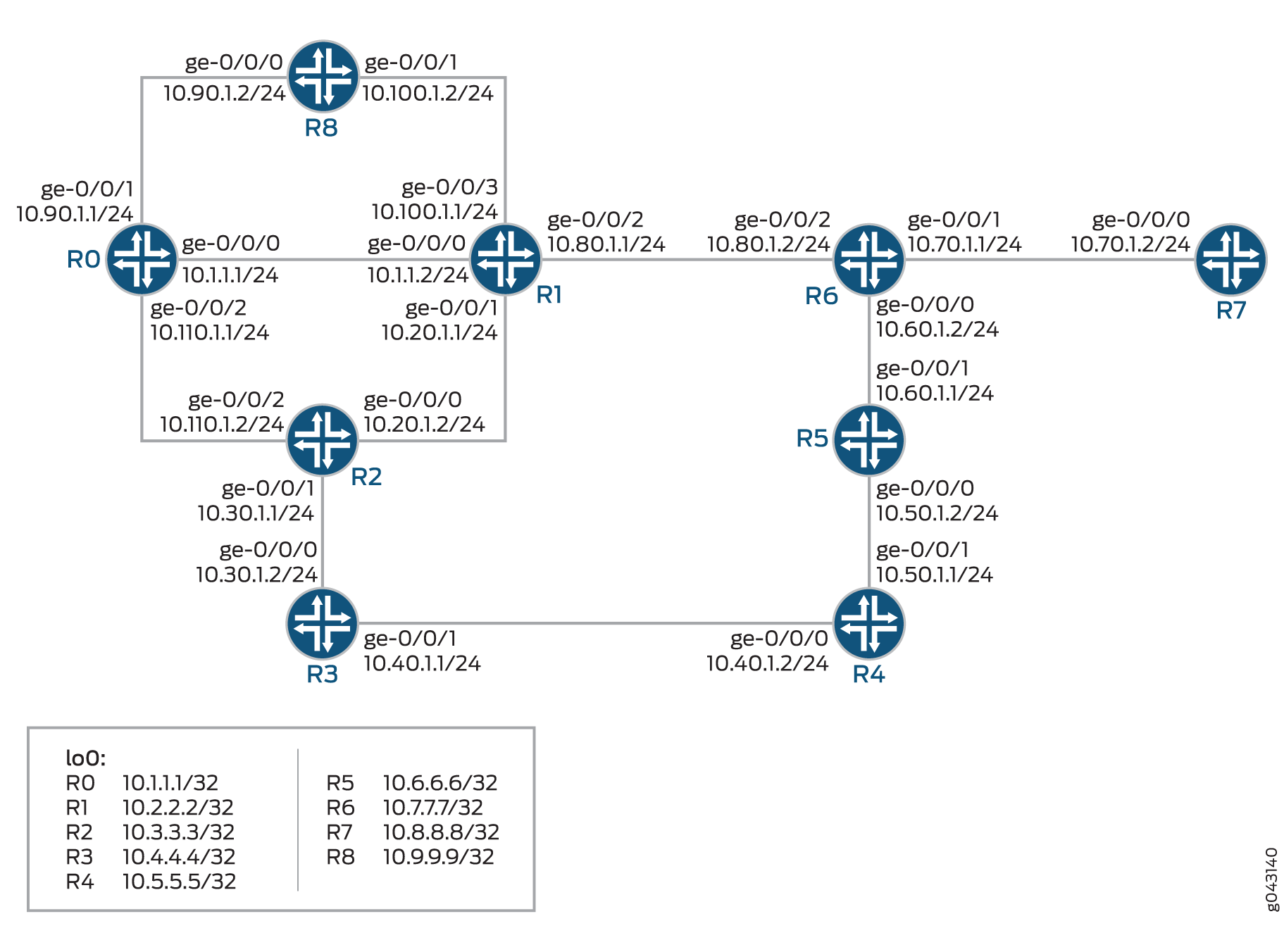
The example includes nine routers in a ring topology. Configure the OSPF protocol on the directly connected interfaces. Device R6 is the PLR. This example verifies that Junos OS updates the routing table of Device R6 with LDP next-hop routes as the backup route.
Topology
In the topology Figure 3 shows the remote LFA over LDP tunnels in OSPF networks is configured on Device R6.
Configuration
CLI Quick Configuration
To quickly configure this example, copy the following commands, paste them into a
text file, remove any line breaks, change any details necessary to match your
network configuration, copy and paste the commands into the CLI at the
[edit] hierarchy level, and then enter
commit from configuration mode.
R0
set interfaces ge-0/0/0 unit 0 family inet address 10.1.1.1/24
set interfaces ge-0/0/0 unit 0 family mpls
set interfaces ge-0/0/1 unit 0 family inet address 10.90.1.1/24
set interfaces ge-0/0/1 unit 0 family mpls
set interfaces ge-0/0/2 unit 0 family inet address 10.110.1.1/24
set interfaces ge-0/0/2 unit 0 family mpls
set interfaces lo0 unit 0 family inet address 10.1.1.1/32
set interfaces lo0 unit 0 family mpls
set routing-options router-id 10.1.1.1
set routing-options forwarding-table export per-packet
set protocols mpls interface ge-0/0/0.0
set protocols mpls interface ge-0/0/1.0
set protocols mpls interface ge-0/0/2.0
set protocols mpls interface lo0.0
set protocols ospf backup-spf-options remote-backup-calculation
set protocols ospf export static
set protocols ospf area 0.0.0.0 interface ge-0/0/0.0
set protocols ospf area 0.0.0.0 interface ge-0/0/1.0
set protocols ospf area 0.0.0.0 interface ge-0/0/2.0
set protocols ospf area 0.0.0.0 interface lo0.0
set protocols ldp auto-targeted-session teardown-delay 20
set protocols ldp auto-targeted-session maximum-sessions 60
set protocols ldp egress-policy static
set protocols ldp interface ge-0/0/0.0
set protocols ldp interface ge-0/0/1.0
set protocols ldp interface ge-0/0/2.0
set protocols ldp interface lo0.0
set policy-options policy-statement per-packet then load-balance per-packet
set policy-options policy-statement per-packet then accept
set policy-options policy-statement static from protocol static
set policy-options policy-statement static then accept
R1
set interfaces ge-0/0/0 unit 0 family inet address 10.1.1.2/24
set interfaces ge-0/0/0 unit 0 family mpls
set interfaces ge-0/0/1 unit 0 family inet address 10.20.1.1/24
set interfaces ge-0/0/1 unit 0 family mpls
set interfaces ge-0/0/2 unit 0 family inet address 10.80.1.1/24
set interfaces ge-0/0/2 unit 0 family mpls
set interfaces ge-0/0/3 unit 0 family inet address 10.100.1.1/24
set interfaces ge-0/0/3 unit 0 family mpls
set interfaces lo0 unit 0 family inet address 10.2.2.2/32
set interfaces lo0 unit 0 family mpls
set routing-options router-id 10.2.2.2
set routing-options forwarding-table export per-packet
set protocols ospf backup-spf-options remote-backup-calculation
set protocols ospf traffic-engineering
set protocols ospf area 0.0.0.0 interface ge-0/0/0.0
set protocols ospf area 0.0.0.0 interface ge-0/0/2.0
set protocols ospf area 0.0.0.0 interface ge-0/0/1.0 link-protection
set protocols ospf area 0.0.0.0 interface ge-0/0/3.0
set protocols ospf area 0.0.0.0 interface lo0.0
set protocols ldp auto-targeted-session teardown-delay 20
set protocols ldp auto-targeted-session maximum-sessions 60
set protocols ldp interface ge-0/0/0.0
set protocols ldp interface ge-0/0/1.0
set protocols ldp interface ge-0/0/2.0
set protocols ldp interface ge-0/0/3.0
set protocols ldp interface lo0.0
set policy-options policy-statement per-packet then load-balance per-packet
set policy-options policy-statement per-packet then accept
R2
set interfaces ge-0/0/0 unit 0 family inet address 10.20.1.2/24
set interfaces ge-0/0/0 unit 0 family mpls
set interfaces ge-0/0/1 unit 0 family inet address 10.30.1.1/24
set interfaces ge-0/0/1 unit 0 family mpls
set interfaces ge-0/0/2 unit 0 family inet address 10.110.1.1/24
set interfaces ge-0/0/2 unit 0 family mpls
set interfaces lo0 unit 0 family inet address 10.3.3.3/32
set interfaces lo0 unit 0 family mpls
set protocols ospf area 0.0.0.0 interface all
set protocols ospf area 0.0.0.0 interface fxp0.0 disable
set policy-options policy-statement per-packet then load-balance per-packet
set policy-options policy-statement per-packet then accept
R3
set interfaces ge-0/0/0 unit 0 family inet address 10.30.1.2/24
set interfaces ge-0/0/0 unit 0 family mpls
set interfaces ge-0/0/1 unit 0 family inet address 10.40.1.1/24
set interfaces ge-0/0/1 unit 0 family mpls
set interfaces lo0 unit 0 family inet address 10.4.4.4/32
set interfaces lo0 unit 0 family mpls
set routing-options router-id 10.4.4.4
set routing-options forwarding-table export per-packet
set protocols ospf backup-spf-options remote-backup-calculation
set protocols ospf traffic-engineering
set protocols ospf area 0.0.0.0 interface ge-0/0/0.0
set protocols ospf area 0.0.0.0 interface ge-0/0/1.0
set protocols ospf area 0.0.0.0 interface lo0.0
set protocols ldp auto-targeted-session teardown-delay 20
set protocols ldp auto-targeted-session maximum-sessions 60
set protocols ldp interface ge-0/0/0.0
set protocols ldp interface ge-0/0/1.0
set protocols ldp interface lo0.0
set policy-options policy-statement per-packet then load-balance per-packet
set policy-options policy-statement per-packet then accept
R4
set interfaces ge-0/0/0 unit 0 family inet address 10.40.1.2/24
set interfaces ge-0/0/0 unit 0 family mpls
set interfaces ge-0/0/1 unit 0 family inet address 10.50.1.1/24
set interfaces ge-0/0/1 unit 0 family mpls
set interfaces lo0 unit 0 family inet address 10.5.5.5/32
set interfaces lo0 unit 0 family mpls
set routing-options router-id 10.5.5.5
set routing-options forwarding-table export per-packet
set protocols ospf backup-spf-options remote-backup-calculation
set protocols ospf traffic-engineering
set protocols ospf area 0.0.0.0 interface ge-0/0/0.0
set protocols ospf area 0.0.0.0 interface ge-0/0/1.0
set protocols ospf area 0.0.0.0 interface lo0.0
set protocols ldp auto-targeted-session teardown-delay 60
set protocols ldp auto-targeted-session maximum-sessions 20
set protocols ldp interface ge-0/0/0.0
set protocols ldp interface ge-0/0/1.0
set protocols ldp interface lo0.0
set policy-options policy-statement per-packet then load-balance per-packet
set policy-options policy-statement per-packet then accept
R5
set interfaces ge-0/0/0 unit 0 family inet address 10.50.1.2/24
set interfaces ge-0/0/0 unit 0 family mpls
set interfaces ge-0/0/1 unit 0 family inet address 10.60.1.1/24
set interfaces ge-0/0/1 unit 0 family mpls
set interfaces lo0 unit 0 family inet address 10.6.6.6/32
set interfaces lo0 unit 0 family mpls
set routing-options router-id 10.6.6.6
set routing-options forwarding-table export per-packet
set protocols ospf backup-spf-options remote-backup-calculation
set protocols ospf traffic-engineering
set protocols ospf area 0.0.0.0 interface ge-0/0/0.0
set protocols ospf area 0.0.0.0 interface ge-0/0/1.0
set protocols ospf area 0.0.0.0 interface lo0.0
set protocols ldp auto-targeted-session teardown-delay 20
set protocols ldp auto-targeted-session maximum-sessions 60
set protocols ldp interface ge-0/0/0.0
set protocols ldp interface ge-0/0/1.0
set protocols ldp interface lo0.0
set policy-options policy-statement per-packet then load-balance per-packet
set policy-options policy-statement per-packet then accept
R6
set interfaces ge-0/0/0 unit 0 family inet address 10.60.1.2/24
set interfaces ge-0/0/0 unit 0 family mpls
set interfaces ge-0/0/1 unit 0 family inet address 10.70.1.1/24
set interfaces ge-0/0/1 unit 0 family mpls
set interfaces ge-0/0/2 unit 0 family inet address 10.80.1.2/24
set interfaces ge-0/0/2 unit 0 family mpls
set interfaces lo0 unit 0 family inet address 10.7.7.7/32
set interfaces lo0 unit 0 family mpls
set routing-options router-id 10.7.7.7
set routing-options forwarding-table export per-packet
set protocols ospf topology default backup-spf-options remote-backup-calculation
set protocols ospf backup-spf-options remote-backup-calculation
set protocols ospf traffic-engineering
set protocols ospf area 0.0.0.0 interface ge-0/0/0.0 link-protection
set protocols ospf area 0.0.0.0 interface ge-0/0/1.0 link-protection
set protocols ospf area 0.0.0.0 interface ge-0/0/2.0 link-protection
set protocols ospf area 0.0.0.0 interface lo0.0
set protocols ldp auto-targeted-session teardown-delay 20
set protocols ldp auto-targeted-session maximum-sessions 60
set protocols ldp interface ge-0/0/0.0
set protocols ldp interface ge-0/0/1.0
set protocols ldp interface ge-0/0/2.0
set protocols ldp interface lo0.0
set policy-options policy-statement per-packet then load-balance per-packet
set policy-options policy-statement per-packet then accept
R7
set interfaces ge-0/0/0 unit 0 family inet address 10.70.1.2/24
set interfaces ge-0/0/0 unit 0 family mpls
set interfaces lo0 unit 0 family inet address 10.8.8.8/32
set interfaces lo0 unit 0 family mpls
set routing-options router-id 10.8.8.8
set routing-options forwarding-table export per-packet
set protocols mpls interface ge-0/0/0.0
set protocols mpls interface lo0.0
set protocols ospf backup-spf-options remote-backup-calculation
set protocols ospf area 0.0.0.0 interface ge-0/0/0.0
set protocols ospf area 0.0.0.0 interface lo0.0
set protocols ldp auto-targeted-session teardown-delay 20
set protocols ldp auto-targeted-session maximum-sessions 60
set protocols ldp interface ge-0/0/0.0
set protocols ldp interface lo0.0
set policy-options policy-statement per-packet then load-balance per-packet
set policy-options policy-statement per-packet then accept
R8
set interfaces ge-0/0/0 unit 0 family inet address 10.90.1.2/24
set interfaces ge-0/0/0 unit 0 family mpls
set interfaces ge-0/0/1 unit 0 family inet address 10.100.1.2/24
set interfaces ge-0/0/1 unit 0 family mpls
set interfaces lo0 unit 0 family inet address 10.9.9.9/32
set interfaces lo0 unit 0 family mpls
set routing-options router-id 10.9.9.9
set routing-options forwarding-table export per-packet
set protocols mpls interface ge-0/0/0.0
set protocols mpls interface ge-0/0/1.0
set protocols mpls interface lo0.0
set protocols ospf backup-spf-options remote-backup-calculation
set protocols ospf area 0.0.0.0 interface ge-0/0/0.0
set protocols ospf area 0.0.0.0 interface ge-0/0/1.0
set protocols ospf area 0.0.0.0 interface lo0.0
set protocols ldp auto-targeted-session teardown-delay 20
set protocols ldp auto-targeted-session maximum-sessions 60
set protocols ldp interface ge-0/0/0.0
set protocols ldp interface ge-0/0/1.0
set protocols ldp interface lo0.0
set policy-options policy-statement per-packet then load-balance per-packet
set policy-options policy-statement per-packet then accept
Configuring Device R6
Step-by-Step Procedure
The following example requires that you navigate various levels in the configuration hierarchy. For information about navigating the CLI, see Using the CLI Editor in Configuration Mode in the CLI User Guide.
To configure Device R6:
-
Configure the interfaces.
[edit interfaces]
user@R6# set ge-0/0/0 unit 0 family inet address 10.60.1.2/24
user@R6# set ge-0/0/0 unit 0 family mpls
user@R6# set ge-0/0/1 unit 0 family inet address 10.70.1.1/24
user@R6# set ge-0/0/1 unit 0 family mpls
user@R6# set ge-0/0/2 unit 0 family inet address 10.80.1.2/24
user@R6# set ge-0/0/2 unit 0 family mpls
-
Assign the loopback addresses to the device.
[edit lo0 unit 0 family]
user@R6# set address 10.7.7.7/32
user@R6# set mpls
-
Configure the router ID. Apply the policy to the forwarding table of the local router with the export statement.
[edit routing-options]
user@R6# set router-id 10.7.7.7
user@R6# set forwarding-table export per-packet
-
Enable remote LFA backup which calculates the backup next hop using dynamic LDP label-switched path.
[edit protocols ospf]
user@R6# set topology default backup-spf-options remote-backup-calculation
user@R6# set backup-spf-options remote-backup-calculation
-
Configure the traffic engineering and the link protection for the interfaces in the OSPF area.
[edit protocols ospf]
user@R6# set traffic-engineering
user@R6# set area 0.0.0.0 interface ge-0/0/0.0 link-protection
user@R6# set area 0.0.0.0 interface ge-0/0/1.0 link-protection
user@R6# set area 0.0.0.0 interface ge-0/0/2.0 link-protection
user@R6# set area 0.0.0.0 interface lo0.0
-
Specify a time interval for which the targeted LDP sessions are kept up when the remote LFA goes down, and specify a maximum number of automatically, targeted LDP sessions to optimize the use of memory.
[edit protocols ldp]
user@R6# set auto-targeted-session teardown-delay 20
user@R6# set auto-targeted-session maximum-sessions 60
-
Configure the LDP protocols on the interfaces.
[edit protocols ldp]
user@R6# set interface ge-0/0/0.0
user@R6# set interface ge-0/0/1.0
user@R6# set interface ge-0/0/2.0
user@R6# set interface lo0.0
-
Configure the policy options to load balance the per-packet of the policy-statement routing policy.
[edit policy-options policy-statement]
user@R6# set per-packet then load-balance per-packet
user@R6# set per-packet then accept
Results
From configuration mode, confirm your configuration by entering the show interfaces, show protocols, show policy-options, and show routing-options commands. If the output does not display the intended configuration, repeat the instructions in this example to correct the configuration.
user@R6# show interfaces
ge-0/0/0 {
    unit 0 {
        family inet {
            address 10.60.1.2/24;
        }
        family mpls;
    }
}
ge-0/0/1 {
    unit 0 {
        family inet {
            address 10.70.1.1/24;
        }
        family mpls;
    }
}
ge-0/0/2 {
    unit 0 {
        family inet {
            address 10.80.1.2/24;
        }
        family mpls;
    }
}
lo0 {
    unit 0 {
        family inet {
            address 10.7.7.7/32;
        }
        family mpls;
    }
}
user@R6# show protocols
ospf {
    topology default {
        backup-spf-options {
            remote-backup-calculation;
        }
    }
    backup-spf-options {
        remote-backup-calculation;
        inactive: per-prefix-calculation all;
    }
    traffic-engineering;
    area 0.0.0.0 {
        interface ge-0/0/0.0 {
            link-protection;
        }
        interface ge-0/0/1.0 {
            link-protection;
        }
        interface ge-0/0/2.0 {
            link-protection;
        }
        interface lo0.0;
    }
}
ldp {
    auto-targeted-session {
        teardown-delay 20;
        maximum-sessions 60;
    }
    interface ge-0/0/0.0;
    interface ge-0/0/1.0;
    interface ge-0/0/2.0;
    interface lo0.0;
}
user@R6# show policy-options
policy-statement per-packet {
    then {
        load-balance per-packet;
        accept;
    }
}
user@R6# show routing-options
router-id 10.7.7.7;
forwarding-table {
    export per-packet;
}
If you are done configuring the device, enter commit from the
configuration mode.
Verification
Confirm that the configuration is working properly.
- Verifying the Routes
- Verifying the LDP Routes
- Verifying the OSPF Routes
- Verifying the Designated Backup Path Node
- Verifying the Backup Neighbors
Verifying the Routes
Purpose
Verify that the expected routes are learned.
Action
On Device R6, from operational mode, run the show route
10.6.6.6/24
command to display the routes in the routing table.
user@R6> show route 10.6.6.6/24

inet.0: 75 destinations, 75 routes (75 active, 0 holddown, 0 hidden)
+ = Active Route, - = Last Active, * = Both

10.6.6.6/32         *[OSPF/10] 02:21:07, metric 1
                    > to 10.60.1.1 via ge-0/0/0.0
                      to 10.80.1.1 via ge-0/0/2.0, Push 299872

inet.3: 7 destinations, 7 routes (7 active, 0 holddown, 0 hidden)
+ = Active Route, - = Last Active, * = Both

10.6.6.6/32         *[LDP/9] 02:21:07, metric 1
                    > to 10.60.1.1 via ge-0/0/0.0
                      to 10.80.1.1 via ge-0/0/2.0, Push 299792, Push 299872(top)
inet.0: 75 destinations, 75 routes (75 active, 0 holddown, 0 hidden)
10.6.6.6/32 (1 entry, 1 announced)
        State: <FlashAll>
        *OSPF   Preference: 10
                Next hop type: Router, Next hop index: 1048585
                Address: 0x9df2690
                Next-hop reference count: 10
                Next hop: 10.60.1.1 via ge-0/0/0.0 weight 0x1, selected
                Session Id: 0x141
                Next hop: 10.80.1.1 via ge-0/0/2.0 weight 0x101 uflags Remote neighbor path
                Label operation: Push 299872
                Label TTL action: prop-ttl
                Load balance label: Label 299872: None;
                Label element ptr: 0x9dc27a0
                Label parent element ptr: 0x0
                Label element references: 6
                Label element child references: 4
                Label element lsp id: 0
                Session Id: 0x142
                State: <Active Int>
                Age: 2:22:40    Metric: 1
                Validation State: unverified
                Area: 0.0.0.0
                Task: OSPF
                Announcement bits (2): 0-KRT 4-LDP
                AS path: I

inet.3: 7 destinations, 7 routes (7 active, 0 holddown, 0 hidden)

10.6.6.6/32 (1 entry, 1 announced)
State: <FlashAll>
        *LDP    Preference: 9
                Next hop type: Router, Next hop index: 0
                Address: 0x9df2a90
                Next-hop reference count: 1
                Next hop: 10.60.1.1 via ge-0/0/0.0 weight 0x1, selected
                Label element ptr: 0x9dc0dc0
                Label parent element ptr: 0x0
                Label element references: 1
                Label element child references: 0
                Label element lsp id: 0
                Session Id: 0x0
                Next hop: 10.80.1.1 via ge-0/0/2.0 weight 0x101 uflags Remote neighbor path
                Label operation: Push 299792, Push 299872(top)
                Label TTL action: prop-ttl, prop-ttl(top)
                Load balance label: Label 299792: None; Label 299872: None;
                Label element ptr: 0x9dc1ba0
                Label parent element ptr: 0x9dc27a0
                Label element references: 1
                Label element child references: 0
                Label element lsp id: 0
                Session Id: 0x0
                State: <Active Int>
                Age: 2:22:40    Metric: 1
                Validation State: unverified
                Task: LDP
                Announcement bits (1): 0-Resolve tree 1
                AS path: I
Meaning
The output shows all the routes in the routing table of Device R6.
Verifying the LDP Routes
Purpose
Verify the automatically targeted LDP routes.
Action
From operational mode, enter the show ldp session auto-targeted
detail command.
user@R6>show ldp session auto-targeted detail

  Address: 10.4.4.4, State: Operational, Connection: Open, Hold time: 28
  Session ID: 10.7.7.7:0--10.4.4.4:0
  Next keepalive in 8 seconds
  Active, Maximum PDU: 4096, Hold time: 30, Neighbor count: 1
  Neighbor types: auto-targeted
  Keepalive interval: 10, Connect retry interval: 1
  Local address: 10.7.7.7, Remote address: 10.4.4.4
  Up for 02:28:28
  Capabilities advertised: none
  Capabilities received: none
  Protection: disabled
  Session flags: none
  Local - Restart: disabled, Helper mode: enabled
  Remote - Restart: disabled, Helper mode: enabled
  Local maximum neighbor reconnect time: 120000 msec
  Local maximum neighbor recovery time: 240000 msec
  Local Label Advertisement mode: Downstream unsolicited
  Remote Label Advertisement mode: Downstream unsolicited
  Negotiated Label Advertisement mode: Downstream unsolicited
  MTU discovery: disabled
  Nonstop routing state: Not in sync
  Next-hop addresses received:
    10.4.4.4
    10.30.1.2
    10.40.1.1
Verifying the OSPF Routes
Purpose
Display all the LDP backup routes in the OSPF routing table of Device R6.
Action
On Device R6, from operational mode, run the show ospf route
command to display the routes in the OSPF routing table.
user@R6> show ospf route
Topology default Route Table:

Prefix             Path  Route      NH       Metric NextHop       Nexthop
                   Type  Type       Type            Interface     Address/LSP
10.1.1.1            Intra AS BR      IP            2 ge-0/0/2.0    10.80.1.1
                                    Bkup LSP                      LDP->10.4.4.4
10.2.2.2            Intra Router     IP            1 ge-0/0/2.0    10.80.1.1
                                    Bkup LSP                      LDP->10.4.4.4
10.4.4.4            Intra Router     IP            3 ge-0/0/0.0    10.60.1.1
                                                    ge-0/0/2.0    10.80.1.1
10.5.5.5            Intra Router     IP            2 ge-0/0/0.0    10.60.1.1
                                    Bkup LSP                      LDP->10.4.4.4
10.6.6.6            Intra Router     IP            1 ge-0/0/0.0    10.60.1.1
                                    Bkup LSP                      LDP->10.4.4.4
10.8.8.8            Intra Router     IP            1 ge-0/0/1.0    10.70.1.2
10.9.9.9            Intra Router     IP            2 ge-0/0/2.0    10.80.1.1
                                    Bkup LSP                      LDP->10.4.4.4
10.1.1.1/32         Intra Network    IP            2 ge-0/0/2.0    10.80.1.1
                                    Bkup LSP                      LDP->10.4.4.4
10.2.2.2/32         Intra Network    IP            1 ge-0/0/2.0    10.80.1.1
                                    Bkup LSP                      LDP->10.4.4.4
10.3.3.3/32         Intra Network    IP            2 ge-0/0/2.0    10.80.1.1
                                    Bkup LSP                      LDP->10.4.4.4
10.4.4.4/32         Intra Network    IP            3 ge-0/0/0.0    10.60.1.1
                                                    ge-0/0/2.0    10.80.1.1
10.5.5.5/32         Intra Network    IP            2 ge-0/0/0.0    10.60.1.1
                                    Bkup LSP                      LDP->10.4.4.4
10.6.6.6/32         Intra Network    IP            1 ge-0/0/0.0    10.60.1.1
                                    Bkup LSP                      LDP->10.4.4.4
10.7.7.7/32         Intra Network    IP            0 lo0.0
10.8.8.8/32         Intra Network    IP            1 ge-0/0/1.0    10.70.1.2
10.9.9.9/32         Intra Network    IP            2 ge-0/0/2.0    10.80.1.1
                                    Bkup LSP                      LDP->10.4.4.4
10.1.1.0/24        Intra Network    IP            2 ge-0/0/2.0    10.80.1.1
                                    Bkup LSP                      LDP->10.4.4.4
10.20.1.0/24        Intra Network    IP            2 ge-0/0/2.0    10.80.1.1
                                    Bkup LSP                      LDP->10.4.4.4
10.30.1.0/24        Intra Network    IP            3 ge-0/0/2.0    10.80.1.1
                                    Bkup IP         ge-0/0/0.0    10.60.1.1
10.40.1.0/24        Intra Network    IP            3 ge-0/0/0.0    10.60.1.1
                                    Bkup IP         ge-0/0/2.0    10.80.1.1
10.50.1.0/24        Intra Network    IP            2 ge-0/0/0.0    10.60.1.1
                                    Bkup LSP                      LDP->10.4.4.4
10.60.1.0/24        Intra Network    IP            1 ge-0/0/0.0
10.70.1.0/24        Intra Network    IP            1 ge-0/0/1.0
10.80.1.0/24        Intra Network    IP            1 ge-0/0/2.0
90.1.1.0/24        Intra Network    IP            3 ge-0/0/2.0    10.80.1.1
                                    Bkup LSP                      LDP->10.4.4.4
10.100.1.0/24       Intra Network    IP            2 ge-0/0/2.0    10.80.1.1
                                    Bkup LSP                      LDP->10.4.4.4
10.110.1.0/24       Intra Network    IP            3 ge-0/0/2.0    10.80.1.1
                                    Bkup LSP                      LDP->10.4.4.4
Meaning
The output shows all the LDP backup routes in the OSPF routing table of Device R6.
Verifying the Designated Backup Path Node
Purpose
Display the remote LFA next hop determined for a given destination.
Action
From operational mode, enter the show ospf backup spf
results command.
user@R6> show ospf backup spf results

Topology default results:

Area 0.0.0.0 results:

10.6.6.6
  Self to Destination Metric: 1
  Parent Node: 10.60.1.2
  Primary next-hop: ge-0/0/0.0 via 60.1.1.1
  Backup next-hop: LDP->10.4.4.4 via ge-0/0/2.0
  Backup Neighbor: 10.6.6.6 via: Direct
    Neighbor to Destination Metric: 0, Neighbor to Self Metric: 1
    Self to Neighbor Metric: 1, Backup preference: 0x0
    Not eligible, Reason: Primary next-hop link fate sharing
  Backup Neighbor: 10.2.2.2 via: Direct
    Neighbor to Destination Metric: 2, Neighbor to Self Metric: 1
    Self to Neighbor Metric: 1, Backup preference: 0x0
    Not eligible, Reason: Path loops
  Backup Neighbor: 10.8.8.8 via: Direct
    Neighbor to Destination Metric: 2, Neighbor to Self Metric: 1
    Self to Neighbor Metric: 1, Backup preference: 0x0
    Not eligible, Reason: Path loops
  Backup Neighbor: 10.4.4.4 via: LDP (LSP endpoint)
    Neighbor to Destination Metric: 2, Neighbor to Self Metric: 3
    Self to Neighbor Metric: 3, Backup preference: 0x0
    Eligible, Reason: Contributes backup next-hop
Meaning
The output indicates whether a specific interface or node has been designated as a remote backup path and why.
Verifying the Backup Neighbors
Purpose
Display the backup neighbors for the Device R6
Action
From operational mode, enter the show ospf backup neighbor
command.
user@R6>show ospf backup neighbor

Topology default backup neighbors:

Area 0.0.0.0 backup neighbors:

10.6.6.6 via: Direct
  Neighbor to Self Metric: 1
  Self to Neighbor Metric: 1
  Direct next-hop: ge-0/0/0.0 via 10.60.1.1

10.8.8.8 via: Direct
  Neighbor to Self Metric: 1
  Self to Neighbor Metric: 1
  Direct next-hop: ge-0/0/1.0 via 10.70.1.2

10.2.2.2 via: Direct
  Neighbor to Self Metric: 1
  Self to Neighbor Metric: 1
  Direct next-hop: ge-0/0/2.0 via 10.80.1.1

10.4.4.4 via: LDP (LSP endpoint)
  Neighbor to Self Metric: 3
  Self to Neighbor Metric: 3
  Direct next-hop: LDP->10.4.4.4 via ge-0/0/2.0
  Direct next-hop: LDP->10.4.4.4 via ge-0/0/0.0
  Neighbors Protected: 2
Meaning
The output displays the backup neighbors available for area 0.0.0.0.