NFX350 Overview
The Juniper Networks NFX350 Network Services Platform is a secure, automated, software-driven customer premises equipment (CPE) platform that delivers virtualized network and security services on demand. The NFX350 is part of the Juniper Cloud CPE solution, which leverages Network Functions Virtualization (NFV).
The NFX350 platform completes the uCPE portfolio to provide end-to-end platforms for medium, large, and extra-large deployments. In addition to IPsec and SD-WAN functionality, the NFX350 provides features such as LAN or WAN isolation, software and hardware resiliency, redundant power supply, Baseboard Management Controller, and serial over LAN.
The NFX350 has the Intel Skylake-D processor which provides increased throughput and cache. Integrated QAT helps accelerate applications that perform cryptographic operations such as IPsec.
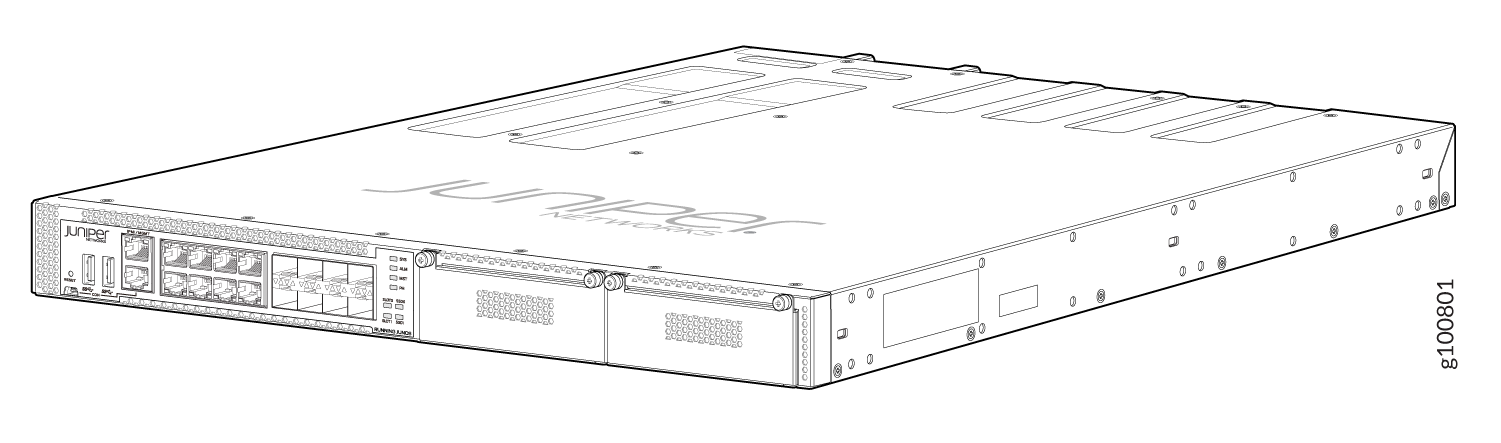
Figure 1 shows the NFX350 device.
Some typical deployment scenarios where you can use the NFX350 are:
-
MSP/SP large/extra-large deployments requiring platform resiliency
-
IOT gateway
-
Resource-intensive deployments
Software Architecture
The architecture is designed to provide a unified control plane that functions as a single management point. Key components in the software include the JCP, JDM, Layer 2 data plane, Layer 3 data plane, and VNFs.
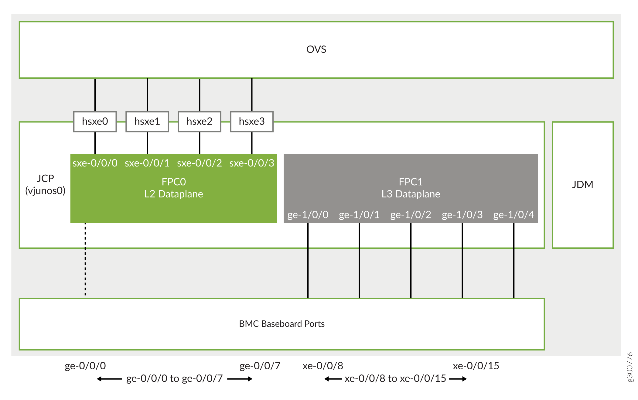
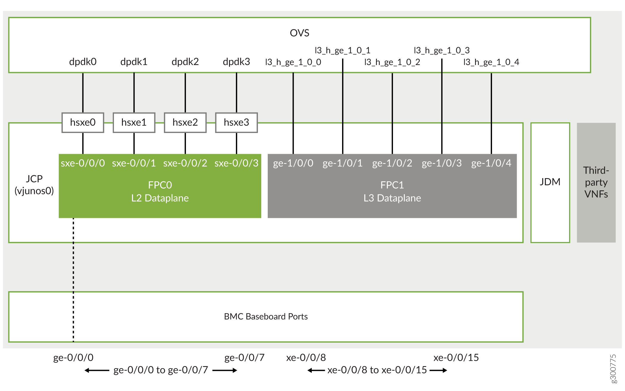
Figure 2 and Figure 3 illustrate the software architecture of the NFX350 in throughput, hybrid, and compute modes.
Key components of the system software include:
-
Linux—The host OS, which functions as the hypervisor.
-
VNF—A VNF is a virtualized implementation of a network device and its functions. Linux functions as the hypervisor, and it creates and runs the VNFs. The VNFs include functions such as firewalls, routers, and WAN accelerators.
You can connect VNFs together as blocks in a chain to provide networking services. The NFX350 supports up to eight VNFs thereby enabling increased network functions and port density.
-
JCP—Junos virtual machine (VM) running on the host OS, Linux. The JCP functions as the single point of management for all the components.
The JCP supports:
-
Layer 2 to Layer 3 routing services
-
Layer 3 to Layer 4 security services
-
Layer 4 to Layer 7 advanced security services
In addition, the JCP enables VNF lifecycle management.
-
-
JDM—An application container that manages VNFs and provides infrastructure services. The JDM functions in the background. Users cannot access the JDM directly.
-
L2 data plane—Manages Layer 2 traffic. The Layer 2 dataplane forwards the LAN traffic to the Open vSwitch (OVS) bridge, which acts as the NFV backplane. The Layer 2 dataplane is mapped to the virtual FPC0 on the JCP.
-
L3 data plane—Provides data path functions for the Layer 3 to Layer 7 services. The Layer 3 data plane is mapped to the virtual FPC1 on the JCP.
-
Open vSwitch (OVS) bridge—The OVS bridge is a VLAN-aware system bridge that acts as the NFV backplane to which the VNFs, FPC1, and FPC0 connect. Additionally, you can create custom OVS bridges to isolate connectivity between different VNFs.
On NFX350, you can configure up to 72 OVS interfaces, which includes the VNF and FPC1 interfaces.
For the list of supported features, see Feature Explorer.
NFX350 Models
Table 1 lists the NFX350 device models and its specifications. For more information, see the NFX350 Hardware Guide.
|
NFX350-S1 |
NFX350-S2 |
NFX350-S3 |
|
|---|---|---|---|
|
CPU |
8-core Intel Skylake D-2146NT |
12-core Intel Skylake D-2166NT |
16-core Intel Skylake D-2187NT |
|
RAM |
32 GB |
64 GB |
128 GB |
|
Storage |
100 GB SSD |
100 GB SSD |
100 GB SSD |
|
Form Factor |
Rack |
Rack |
Rack |
|
Ports |
Eight 1-Gigabit Ethernet RJ-45 ports |
Eight 1-Gigabit Ethernet RJ-45 ports |
Eight 1-Gigabit Ethernet RJ-45 ports |
|
Eight 10-Gigabit Ethernet SFP+ ports |
Eight 10-Gigabit Ethernet SFP+ ports |
Eight 10-Gigabit Ethernet SFP+ ports |
|
|
One management/Intelligent Platform Management Interface (IPMI) port |
One management/Intelligent Platform Management Interface (IPMI) port |
One management/Intelligent Platform Management Interface (IPMI) port |
|
|
One console port (RJ-45 and mini-USB) |
One console port (RJ-45 and mini-USB) |
One console port (RJ-45 and mini-USB) |
|
|
Two USB 3.0 port |
Two USB 3.0 port |
Two USB 3.0 port |
|
|
LTE support |
Yes |
Yes |
Yes |
|
Expansion module support |
Two expansion module slots (one dual slot width NFX-LTE-AA/AE expansion module slot width expansion module) |
Two expansion module slots (one dual slot width NFX-LTE-AA/AE expansion module slot width expansion module) |
Two expansion module slots (one dual slot width NFX-LTE-AA/AE expansion module slot width expansion module) |
|
Supported expansion modules |
|
|
|
Interfaces
The NFX350 device includes the following network interfaces:
-
Eight 1-Gigabit Ethernet RJ-45 ports. The ports follow the naming convention, ge-0/0/n, where n ranges from 0 to 7. These ports are used for LAN connectivity.
-
Eight 10-Gigabit uplink ports that support small form-factor pluggable plus (SFP+) transceivers. The ports follow the naming convention xe-0/0/n, where the value of n is ranges from 8 to 15. These ports are used as WAN uplink ports.
-
A dedicated management port labeled MGMT (fxp0) functions as the out-of-band management interface. The fxp0 interface is assigned the IP address 192.168.1.1/24.
-
Four static interfaces, sxe-0/0/0, sxe-0/0/1, sxe-0/0/2, and sxe-0/0/3, which connect the Layer 2 data plane (FPC0) to the OVS backplane.
By default, all the network ports connect to the Layer 2 data plane.
For the list of supported transceivers for your device, see https://apps.juniper.net/hct/product/#prd=NFX350.
Performance Modes
NFX350 devices offer various operational modes. You can either select the operational mode of the device from a pre-defined list of modes or specify a custom mode.
-
Throughput mode—Provides maximum resources (CPU and memory) for Junos software.
Note:Starting in Junos OS Release 21.1R1, mapping OVS to Layer 3 data plane interface is not supported in throughput mode on NFX350 devices. If the OVS mapping is present in releases prior to Junos OS Release 21.1R1, you must change the mapping before upgrading the device to Junos OS Release 21.1R1 to prevent a configuration commit failure.
-
Hybrid mode—Provides a balanced distribution of resources between the Junos software and third-party VNFs.
-
Compute mode—Provides minimal resources for Junos software and maximum resources for third-party VNFs.
-
Custom mode—Provides an option to allocate resources to Layer 3 data plane and NFV backplane.
Note:Compute, hybrid, and throughput modes are supported in Junos OS Release 19.4R1 or later. Custom mode is supported in Junos OS Release 21.1R1 or later.
The default mode is throughput in Junos OS Releases prior to 21.4R1. Starting in Junos OS Release 21.4R1, the default mode is compute.
In throughput mode, you must map SR-IOV VF to Layer 3 data plane interfaces on an NFX350 device. Three SR-IOV (VFs) are reserved from each NIC (SXE or HSXE) to support a maximum of 12 Layer 3 Dataplane interfaces. For example:
user@host# set vmhost virtualization-options interfaces ge-1/0/1 mapping interface hsxe0
You cannot create VNFs on Throughput mode.
In hybrid mode and compute mode, you can map Layer 3 data plane interfaces to either SR-IOV or OVS on an NFX350 device. For example:
Map Layer 3 data plane interfaces to either SR-IOV:
user@host# set vmhost virtualization-options interfaces ge-1/0/1 mapping interface hsxe0
Map Layer 3 Dataplane interfaces to either OVS:
user@host# set vmhost virtualization-options interfaces ge-1/0/1
In hybrid or compute mode, you can create VNFs using the available CPUs on each mode.
You can check the CPU availability by using the show vmhost mode
command. Each VNF can have maximum of eight user interfaces apart from the two
management interfaces. You can attach the VNF interfaces to either OVS or SR-IOV
interfaces.
You cannot attach single VNF interface to both SR-IOV and OVS. However, you can attach different interfaces from the same VNF to SR-IOV and OVS.
Seven SR-IOV (VFs) are reserved from each NIC (SXE or HSXE) to create VNF interfaces,
and supports up to a maximum of 28 SR-IOV VNF interfaces per device. You can view
the available free VFs by using the show system visibility
network.
When the mapping to a particular Layer 3 data plane interface changes between SR-IOV NICs (eg, hsxe0 to hsxe1) or from hsxex to OVS or vice versa, then FPC1 restarts automatically.
To change the current mode, run the request vmhost mode
mode-name command. The request vmhost
mode ? command lists only the pre-defined modes such as hybrid,
compute, and throughput modes.
Before switching to a mode, issue the show system visibility cpu and
show vmhost mode commands to check the availability of CPUs.
When switching between operational modes, ensure that resource and configuration
conflicts do not occur.
For example, if you move from compute mode that supports VNFs to throughput mode that does not support VNFs, conflicts occur:
user@host# run request vmhost mode throughput
error: Mode cannot be changed; Reason: No CPUs are available for VNFs in the desired mode, but there is atleast one VNF currently configured
If the Layer 3 dataplane is not mapped to SR-IOV, then switching from hybrid or compute mode to throughput mode results in an error.
You can define a custom mode template in Junos configuration by using the following commands:
user@host# set vmhost mode custom
                                custom-mode-name layer-3-infrastructure cpu count
                                count
user@host# set vmhost mode custom custom-mode-name layer-3-infrastructure memory size mem-sizeuser@host# set vmhost mode custom custom-mode-name nfv-back-plane cpu count countuser@host# set vmhost mode custom custom-mode-name nfv-back-plane memory size mem-size
Starting in Junos OS Release 22.1R1, you can opt to configure the CPU quota for the
Layer 3 data plane by using the set vmhost mode custom
custom-mode-name layer-3-infrastructure cpu colocation
quota quota-value command, where
quota-value can range from 1 through 99. If you configure
cpu colocation quota, then the sum total of the CPU quotas of
the cpu colocation components must be less than or equal to 100. You must configure
cpu count using numeric values and not keywords like MIN as MIN
can have different values for different components.
The number of CPUs and the specific CPUs (by CPU ID) available for VNF usage in a
custom mode is automatically determined based on the cpu count and
cpu colocation quota in the custom mode configuration and the
internally fixed CPU allocation for other Juniper system components.
The amount of memory, in terms of 1G units, available for VNF usage in a custom mode is automatically determined based on the custom mode specific memory size configuration and the per-SKU internally fixed memory allocation for other Juniper system components. Note that this number is only an approximate value and the actual maximum memory allocation for VNFs might be less than that.
If you do not configure the memory size for a VNF, then the memory is considered as 1G (default value).
CPU count for both NFV backplane and Layer 3 data plane must be configured in integral numbers.
Memory for Layer 3 data plane and NFV backplane must be specified in Gigabytes in a custom mode. The memory specified through a custom mode is created and backed by 1G huge pages for NFV backplane usage and 2M huge pages for Layer 3 data plane usage. It is recommended to configure NFV backplane memory size in integral numbers, whereas Layer 3 data plane memory can be configured in decimals.
You must configure the CPU count and memory for both Layer 3 data plane and NFV backplane. The CPU and memory resources for the remaining Junos software infrastructure is internally determined by the device.
Custom mode template supports a keyword MIN, which is a device-specific pre-defined value for allocating minimal resources.
flex and perf are the custom mode templates that are present in the default Junos configuration.
- flex mode—Uses MIN keyword for allocating
resources to system components such as Layer 3 data plane and NFV backplane. In
this mode, device provides maximum memory and CPUs to third-party VNFs.
To allocate resources in flex mode:
user@host# set vmhost mode custom
                                        custom-mode-name layer-3-infrastructure
                                    cpu count MIN
user@host# set vmhost mode custom custom-mode-name layer-3-infrastructure memory size MINuser@host# set vmhost mode custom custom-mode-name nfv-back-plane cpu count MINuser@host# set vmhost mode custom custom-mode-name nfv-back-plane memory size MIN
In flex mode, you can configure a maximum of:
-
8 IPSec VPN tunnels
-
16 IFL
-
4 IFD
- perf mode—Another example custom mode template that is available in the default Junos configuration.
Currently, Layer 3 data plane supports only MIN in a custom mode for both CPU count and memory size.
When the device is in custom mode with MIN keyword, only basic firewall features are supported and you can use Layer 3 data plane only for IPsec termination.
When you allocate CPUs to NFV backplane and Layer 3 data plane, the device allocates full cores. When a full core is allocated to NFV backplane, both the logical CPUs on that hyper-threaded core are allocated to it. However, to get the optimal performance, the device disables one of the logical CPUs and is still counted as 2 CPUs allocated. When full cores are not available, the device allocates individual CPUs from different cores.
While allocating CPUs for VNF usage, the device allocates full cores. Both the logical CPUs on that core are enabled. When full cores are not available, the device allocates individual CPUs from different cores.
The requested CPU count and memory should not exceed the total CPU count and memory available on the system.
When the device is operating in custom mode, you can make changes to the custom mode configuration. Reboot the device for the changes to take effect.
Commit checks are performed for basic validation when a custom mode is defined in the configuration and when you change the device mode to a custom mode.
You cannot delete a custom mode configuration when the device is operating in the same mode.
To delete a custom mode configuration when the device is operating in custom mode:
-
Change the device mode from custom mode to another mode.
-
Delete the custom mode configuration.
When the device in a custom mode is downgraded to an image that does not support custom mode, then the default throughput mode is applied on the device.
Before performing such an image downgrade process, you must remove all VNF configurations from the device.
When multiple custom modes are configured in the device and when the device is in a custom mode other than the flex or perf custom mode, which are defined in the factory-default Junos configuration, you cannot reset the device configuration to factory-default configuration. Before you reset such a device to factory-default Junos configuration, you must change the device mode to one of the pre-defined modes such as compute, hybrid, throughput, or to the flex or perf custom mode that are already defined in the factory-default configuration.
Core to CPU Mapping on NFX350
The following tables list the CPU to core mappings for the NFX350 models:
| NFX350-S1 | ||||||||
| Core | 0 | 1 | 2 | 3 | 4 | 5 | 6 | 7 |
| CPU | 0, 8 | 1, 9 | 2, 10 | 3, 11 | 4, 12 | 5, 13 | 6, 14 | 7, 15 |
| NFX350-S2 | ||||||||||||
| Core | 0 | 1 | 2 | 3 | 4 | 5 | 6 | 7 | 8 | 9 | 10 | 11 |
| CPU | 0, 12 | 1, 13 | 2, 14 | 3, 15 | 4, 16 | 5, 17 | 6, 18 | 7, 19 | 8, 20 | 9, 21 | 10, 22 | 11, 23 |
| NFX350-S3 | ||||||||||||||||
| Core | 0 | 1 | 2 | 3 | 4 | 5 | 6 | 7 | 8 | 9 | 10 | 11 | 12 | 13 | 14 | 15 |
| CPU | 0, 16 | 1, 17 | 2, 18 | 3, 19 | 4, 20 | 5, 21 | 6, 22 | 7, 23 | 8, 24 | 9, 25 | 10, 26 | 11, 27 | 12, 28 | 13, 29 | 14, 30 | 15, 31 |
Benefits and Uses
The NFX350 provides the following benefits:
-
Highly scalable architecture that supports multiple Juniper VNFs and third-party VNFs on a single device. The modular software architecture provides high performance and scalability for routing, switching, and security enhanced by carrier-class reliability.
-
Integrated security, routing, and switching functionality in a single control plane simplifies management and deployment.
-
A variety of flexible deployments. A distributed services deployment model ensures high availability, performance, and compliance. The device provides an open framework that supports industry standards, protocols, and seamless API integration.
-
Wireless WAN support through the LTE module provides more flexibility in deployments.
-
Secure boot feature safeguards device credentials, automatically authenticates system integrity, verifies system configuration, and enhances overall platform security.
-
Automated configuration eliminates complex device setup and delivers a plug-and-play experience.
-
Increased storage capacity through two external hard disks.
Junos OS Releases Supported on NFX Series Hardware
The Table 2 provides details of Junos OS software releases supported on the NFX Series devices.
NFX Series Platform |
Supported Junos OS Release |
Software Package |
Software Downloads Page |
|---|---|---|---|
NFX150 |
18.1R1 or later |
nfx-3 jinstall-host-nfx-3-x86-64-<release-number>- secure-signed.tgz install-media-host-usb-nfx-3-x86-64-<release-number>- secure.img |
|
|
NFX250 |
17.2R1 through 19.1R1 |
nfx-2 jinstall-host-nfx-2-flex-x86-64-<release-number >-secure-signed.tgz install-media-host-usb-nfx-2-flex-x86-64-<release-number>- secure.img |
|
19.1 R1 or later |
nfx-3 jinstall-host-nfx-3-x86-64-<release-number>-secure-signed.tgz install-media-host-usb-nfx-3-x86-64-<release-number>-secure.img |
||
NFX350 |
19.4 R1 or later |
nfx-3 jinstall-host-nfx-3-x86-64-<release-number>-secure-signed.tgz install-media-host-usb-nfx-3-x86-64-<release-number>-secure.img |