ON THIS PAGE
Example: Configuring Service Chaining for LAN to WAN Routing through Third-party VNFs on NFX350 Devices
This example shows how to configure service chaining for LAN to WAN routing through third-party VNFs on NFX350 devices.
Requirements
This example uses an NFX350 device running Junos OS Release 19.4R1.
Overview
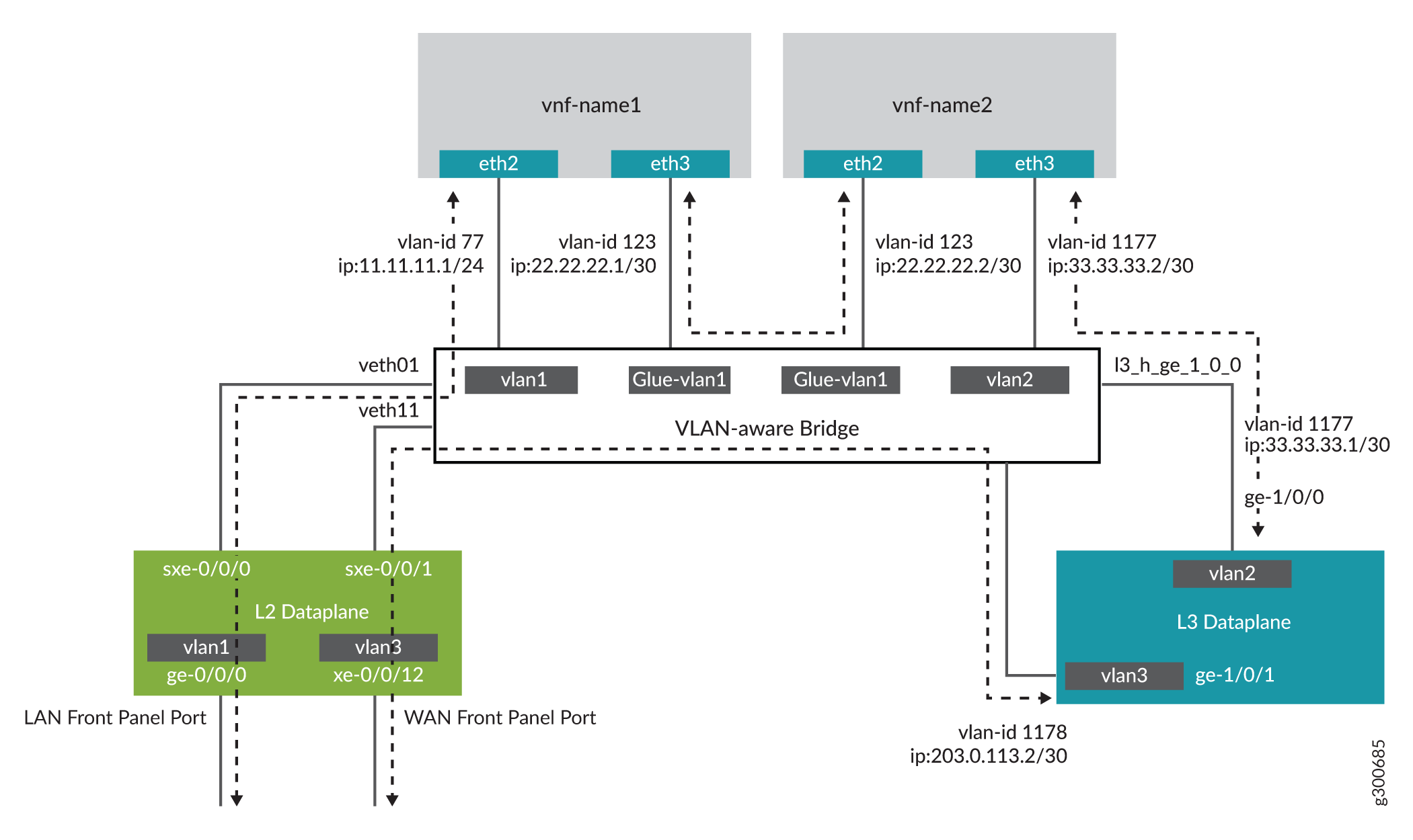
This example explains how to configure the various layers of the device to enable traffic from the LAN network to enter the device, flow through the OVS bridge and third-party VNFs, exit the device, and enter the WAN network.
Topology
This example uses the topology shown in Figure 1.
Configuration
- Configuring the Layer 2 Datapath (JCP LAN Interfaces)
- Verifying the Performance Mode of the NFX350 Device
- Configuring the Hugepages for VNF
- Configuring VNFs
- Configuring the Layer 3 Datapath (WAN Interfaces)
- Configuring the VNF Interfaces for Creating the Service Chain
- Configuring Security in NFX350
- Configuring Security in vSRX Virtual Firewall VNFs
Configuring the Layer 2 Datapath (JCP LAN Interfaces)
Step-by-Step Procedure
Connect to the JCP.
user@host:~ # cli
user@host>
user@host> configure
[edit]
user@host#
Configure VLANs for the LAN-side interfaces.
user@host# set vlans vlan1 vlan-id 77
Configure the LAN-side front panel ports and add them to the LAN-side VLANs. The LAN-side port is typically an access port, and can be a trunk port if required
user@host# set interfaces ge-0/0/0.0 family ethernet-switching vlan members vlan1
Configure the internal-facing interface, sxe-0/0/0, as a trunk port and add it to the LAN-side VLAN. The internal-facing interfaces are typically trunk ports as they must support traffic from multiple front panel ports and VLANs.
user@host# set interfaces sxe-0/0/0.0 family ethernet-switching interface-mode trunk
user@host# set interfaces sxe-0/0/0.0 family ethernet-switching vlan members vlan1
Verifying the Performance Mode of the NFX350 Device
Purpose
Verify the performance mode of the NFX350 device and
check the CPU availability. If the NFX350 device is operating in throughput
mode, you must change it to either compute or hybrid mode by using
the request vmhost mode command.
For more information about the device performance modes, see NFX350 Overview.
Action
user@host> show vmhost mode | no-more
Mode:
--------
Current Mode: compute

CPU Allocations:
Name                                 Configured                               Used
----------------------------------------------------------------------------------------------------------------------
Junos Control Plane                  16                                       16,6
Juniper Device Manager               16                                       16
LTE                                  16                                       -
NFV Backplane Control Path           16                                       16
NFV Backplane Data Path              1,2,3                                    1,2,3
Layer 2 Control Path                 -                                        -
Layer 2 Data Path                    -                                        -
Layer 3 Control Path                 0                                        0
Layer 3 Data Path                    4,5                                      4,5
CPUs available for VNFs              6,7,8,9,10,11,12,13,14,15,22,23,24,25,26,27,28,29,30,31 -
CPUs turned off                      17,18,19,20,21                           -

Memory Allocations:
Name                                 Configured                               Used
----------------------------------------------------------------------------------------------------------------------
Junos Control Plane (mB)             2048                                     2002
NFV Backplane 1G hugepages           12                                       18
NFV Backplane 2M hugepages           -                                        0
Layer 2 1G hugepages                 -                                        -
Layer 2 2M hugepages                 -                                        -
Layer 3 1G hugepages                 6                                        6
Layer 3 2M hugepages                 20481                                    20481
Configuring the Hugepages for VNF
Step-by-Step Procedure
It is recommended to reboot the device if the configured number of hugepages are not allocated.
Check the memory availability:
user@host> show system visibility memory | no-more
Memory Information
------------------

Virtual Memory:
---------------
Total       (KiB): 131042784
Used        (KiB): 67141828
Available   (KiB): 66151972
Free        (KiB): 63900956
Percent Used     : 49.5

Huge Pages:
------------
Total 1GiB Huge Pages:      18
Free 1GiB Huge Pages:       0
Configured 1GiB Huge Pages: 0
Total 2MiB Huge Pages:      20481
Free 2MiB Huge Pages:       0
Configured 2MiB Huge Pages: 0
Configure hugepages:
user@host> configure
[edit]
user@host#
user@host# set system memory hugepages page-size 1024 page-count 10
user@host# commit
Verify whether hugepages is configured:
user@host# run show system visibility memory | no-more
Memory Information
------------------

Virtual Memory:
---------------
Total       (KiB): 131042784
Used        (KiB): 77624220
Available   (KiB): 55670868
Free        (KiB): 53418564
Percent Used     : 57.5

Huge Pages:
------------
Total 1GiB Huge Pages:      28
Free 1GiB Huge Pages:       10
Configured 1GiB Huge Pages: 10
Total 2MiB Huge Pages:      20481
Free 2MiB Huge Pages:       0
Configured 2MiB Huge Pages: 0

Hugepages Usage:
----------------------------------------------------------------------------------------------------------
Name                              Type                               Used 1G Hugepages  Used 2M Hugepages
--------------------------------- ---------------------------------- ------------------ ------------------
ovs-vswitchd                      other process                      18                 0
srxpfe                            other process                      6                  20481
Configuring VNFs
Step-by-Step Procedure
Configure VNF-1:
Load the VNF image on the device from the remote location:
Note:You can save the VNF image in the /var/public directory if you are using up to two VNFs. If you are using more than two VNFs, save the files on an external SSD. If you are using an external SSD for VNFs, make sure to initialize and add the SSD to the device. For more information, see Configuring the Solid State Disk.
user@host> file copy source-address /var/public/vnf-1_junos-vsrx3-x86-64-19.1R1-S1.3.qcow2
Launch the VNF:
user@host> set virtual-network-functions VNF-1 image /var/public/vnf-1_junos-vsrx3-x86-64-19.1R1-S1.3.qcow2
Connect a virtual CPUs to physical CPUs:
user@host> set virtual-network-functions VNF-1 virtual-cpu 0 physical-cpu 6
user@host> set virtual-network-functions VNF-1 virtual-cpu 1 physical-cpu 7
Specify the number of CPUs required for the VNF:
user@host> set virtual-network-functions VNF-1 virtual-cpu count 2
Enable hardware virtualization or hardware acceleration for VNF CPUs:
user@host> set virtual-network-functions VNF-1 virtual-cpu features hardware-virtualization
Configure the VNF interfaces as trunk ports and add them to the LAN-side VLAN:
user@host> set virtual-network-functions VNF-1 interfaces eth2 mapping vlan mode trunk
user@host> set virtual-network-functions VNF-1 interfaces eth2 mapping vlan members vlan1
user@host> set virtual-network-functions VNF-1 interfaces eth3 mapping vlan mode trunk
user@host> set virtual-network-functions VNF-1 interfaces eth3 mapping vlan members glue-vlan1
Specify the memory allocation for the VNF:
user@host> set virtual-network-functions VNF-1 memory size 4194304
user@host> set virtual-network-functions VNF-1 memory features hugepages
Step-by-Step Procedure
Configure VNF-2:
Load the VNF image on the device from the remote location:
user@host> file copy source-address /var/public/vnf-2-junos-vsrx3-x86-64-19.1R1-S1.3.qcow2
Launch the VNF:
user@host> set virtual-network-functions VNF-2 image /var/public/vnf-2-junos-vsrx3-x86-64-19.1R1-S1.3.qcow2
Connect a virtual CPUs to physical CPUs:
user@host> set virtual-network-functions VNF-2 virtual-cpu 0 physical-cpu 8
user@host> set virtual-network-functions VNF-2 virtual-cpu 1 physical-cpu 9
Specify the number of CPUs required for the VNF:
user@host> set virtual-network-functions VNF-2 virtual-cpu count 2
Enable hardware virtualization or hardware acceleration for VNF CPUs:
user@host> set virtual-network-functions VNF-2 virtual-cpu features hardware-virtualization
Configure the VNF interfaces as trunk ports and add them to the LAN-side VLAN:
user@host> set virtual-network-functions VNF-2 interfaces eth2 mapping vlan mode trunk
user@host> set virtual-network-functions VNF-2 interfaces eth2 mapping vlan members glue-vlan1
user@host> set virtual-network-functions VNF-2 interfaces eth3 mapping vlan mode trunk
user@host> set virtual-network-functions VNF-2 interfaces eth3 mapping vlan members vlan2
Specify the memory allocation for the VNF:
user@host> set virtual-network-functions VNF-2 memory size 4194304
user@host> set virtual-network-functions VNF-2 memory features hugepages
Configuring the Layer 3 Datapath (WAN Interfaces)
Step-by-Step Procedure
Configure the internal-facing L3 Dataplane interface as a VLAN-tagged interface and assign an IP address to it:
user@host# set interfaces ge-1/0/0 vlan-tagging
user@host# set interfaces ge-1/0/0.0 vlan-id 1177
user@host# set interfaces ge-1/0/0.0 family inet address 33.33.33.1/30
Map the Layer 3 interface to the Open vSwitch (OVS) and commit the configuration:
user@host# set vmhost virtualization-options interfaces ge-1/0/1
user@host# commit
Configure the external-facing L3 Dataplane interface as a VLAN-tagged interface and assign an IP address to it:
user@host# set interfaces ge-1/0/1 vlan-tagging
user@host# set interfaces ge-1/0/1.0 vlan-id 1178
user@host# set interfaces ge-1/0/1.0 family inet address 203.0.113.2/30
Configure a VLAN for the WAN-side JCP interfaces:
user@host# set vlans vlan3 vlan-id 1178
Configure the WAN-side internal-facing interface as a trunk port and add it to the WAN-side VLAN:
user@host# set interfaces sxe-0/0/1.0 family ethernet-switching interface-mode trunk
user@host# set interfaces sxe-0/0/1.0 family ethernet-switching vlan members vlan3
Configure the WAN-side front panel port and add it to the WAN-side VLAN:
user@host# set interfaces xe-0/0/12.0 family ethernet-switching interface-mode access
user@host# set interfaces xe-0/0/12.0 family ethernet-switching vlan members vlan3
Commit the configuration:
user@host# commit
Configuring the VNF Interfaces for Creating the Service Chain
Step-by-Step Procedure
Check the MAC addresses of the VNF interfaces:
user@host# run show system visibility network
VNF MAC Addresses
-----------------------------------------------------------
VNF                                       MAC
----------------------------------------- -----------------
VNF-1_ethdef0                             D0:DD:49:E8:B6:CA
VNF-1_ethdef1                             D0:DD:49:E8:B6:CB
VNF-1_eth2                                D0:DD:49:E8:B6:CC
VNF-1_eth3                                D0:DD:49:E8:B6:C7
VNF-2_ethdef0                             D0:DD:49:E8:B6:C8
VNF-2_ethdef1                             D0:DD:49:E8:B6:C9
VNF-2_eth2                                D0:DD:49:E8:B6:CD
VNF-2_eth3                                D0:DD:49:E8:B6:CE

VNF Internal IP Addresses
---------------------------------------------------------
VNF                                       IP
----------------------------------------- ---------------
VNF-1                                     192.0.2.100
VNF-2                                     192.0.2.101

Free Virtual Functions
----------------------
PF        VF
--------- ------------
hsxe0     0000:b7:03.6
hsxe0     0000:b7:03.4
hsxe0     0000:b7:03.5
hsxe0     0000:b7:02.3
hsxe0     0000:b7:02.2
hsxe0     0000:b7:02.1
hsxe0     0000:b7:02.7
hsxe0     0000:b7:02.6
hsxe0     0000:b7:02.5
hsxe0     0000:b7:02.4
hsxe1     0000:b7:07.4
hsxe1     0000:b7:06.7
hsxe1     0000:b7:06.6
hsxe1     0000:b7:06.5
hsxe1     0000:b7:06.4
hsxe1     0000:b7:06.3
hsxe1     0000:b7:06.2
hsxe1     0000:b7:06.1
hsxe1     0000:b7:07.5
hsxe1     0000:b7:07.6
hsxe2     0000:b7:0b.6
hsxe2     0000:b7:0b.5
hsxe2     0000:b7:0b.4
hsxe2     0000:b7:0a.4
hsxe2     0000:b7:0a.5
hsxe2     0000:b7:0a.6
hsxe2     0000:b7:0a.7
hsxe2     0000:b7:0a.1
hsxe2     0000:b7:0a.2
hsxe2     0000:b7:0a.3
hsxe3     0000:b7:0f.6
hsxe3     0000:b7:0f.5
hsxe3     0000:b7:0f.4
hsxe3     0000:b7:0e.1
hsxe3     0000:b7:0e.2
hsxe3     0000:b7:0e.3
hsxe3     0000:b7:0e.4
hsxe3     0000:b7:0e.5
hsxe3     0000:b7:0e.6
hsxe3     0000:b7:0e.7

VNF Interfaces
---------------------------------------------------------------------------------------------
VNF                  Interface Type      Source       Model      MAC                  VLAN-ID
-------------------- --------- --------- ------------ ---------- -------------------- -------
VNF-1                vnet4     network   default      virtio     d0:dd:49:e8:b6:ca    --
VNF-1                vnet5     bridge    eth0br       virtio     d0:dd:49:e8:b6:cb    --
VNF-1                VNF-1_eth2 vhostuser --          virtio     d0:dd:49:e8:b6:cc    --
VNF-1                VNF-1_eth3 vhostuser --          virtio     d0:dd:49:e8:b6:c7    --
VNF-2                vnet6     network   default      virtio     d0:dd:49:e8:b6:c8    --
VNF-2                vnet7     bridge    eth0br       virtio     d0:dd:49:e8:b6:c9    --
VNF-2                VNF-2_eth2 vhostuser --          virtio     d0:dd:49:e8:b6:cd    --
VNF-2                VNF-2_eth3 vhostuser --          virtio     d0:dd:49:e8:b6:ce    --

OVS Interfaces
------------------------
NAME              MTU
----------------- ------
ovs-sys-br        1500
dpdk2             9216
xdsl_eth0         9192
l3_h_ge_1_0_1     9216
l3_h_ge_1_0_0     1500
dpdk0             9216
VNF-2_eth2        1500
dpdk1             9216
VNF-1_eth3        1500
dpdk3             9216
VNF-1_eth2        1500
VNF-2_eth3        1500
Access the VNF (VNF-1) from the JCP through the console:
user@host> request virtual-network-functions console VNF-1
Internal instance: VNF-1
Connected to domain VNF-1
Log in to the console:
user@host:~ # cli
user@host>
Check the status of the interfaces:
user@host# show interfaces terse | no-more Interface Admin Link Proto Local Remote ge-0/0/0 up up gr-0/0/0 up up ip-0/0/0 up up lsq-0/0/0 up up lt-0/0/0 up up mt-0/0/0 up up sp-0/0/0 up up sp-0/0/0.0 up up inet inet6 sp-0/0/0.16383 up up inet ge-0/0/1 up up ge-0/0/2 up up dsc up up fti0 up up fxp0 up up fxp0.0 up up gre up up ipip up up irb up up lo0 up up lo0.16384 up up inet 127.0.0.1 --> 0/0 lo0.16385 up up inet 10.0.0.1 --> 0/0 10.0.0.16 --> 0/0 128.0.0.1 --> 0/0 128.0.0.4 --> 0/0 128.0.1.16 --> 0/0 lo0.32768 up up lsi up up mtun up up pimd up up pime up up pp0 up up ppd0 up up ppe0 up up st0 up up tap up up vlan up downuser@host> show interfaces ge-0/0/0 | no-more Physical interface: ge-0/0/0, Enabled, Physical link is Up Interface index: 135, SNMP ifIndex: 508 Link-level type: Ethernet, MTU: 1514, LAN-PHY mode, Link-mode: Half-duplex, Speed: 1000mbps, BPDU Error: None, Loop Detect PDU Error: None, Ethernet-Switching Error: None, MAC-REWRITE Error: None, Loopback: Disabled, Source filtering: Disabled, Flow control: Enabled, Auto-negotiation: Enabled, Remote fault: Online Device flags : Present Running Interface flags: SNMP-Traps Internal: 0x4000 Link flags : None CoS queues : 8 supported, 8 maximum usable queues Current address: d0:dd:49:e8:b6:cb, Hardware address: d0:dd:49:e8:b6:cb Last flapped : 2020-05-11 10:22:06 UTC (00:46:40 ago) Input rate : 0 bps (0 pps) Output rate : 0 bps (0 pps) Active alarms : None Active defects : None PCS statistics Seconds Bit errors 0 Errored blocks 0 Ethernet FEC statistics Errors FEC Corrected Errors 0 FEC Uncorrected Errors 0 FEC Corrected Errors Rate 0 FEC Uncorrected Errors Rate 0 Interface transmit statistics: Disableduser@host> show interfaces fxp0 | no-more Physical interface: fxp0, Enabled, Physical link is Up Interface index: 65, SNMP ifIndex: 1 Type: Ethernet, Link-level type: Ethernet, MTU: 1514, Speed: 1000mbps Device flags : Present Running Interface flags: SNMP-Traps Link type : Full-Duplex Current address: d0:dd:49:e8:b6:ca, Hardware address: d0:dd:49:e8:b6:ca Last flapped : 2020-05-11 10:21:26 UTC (00:47:53 ago) Input packets : 1484 Output packets: 0 Logical interface fxp0.0 (Index 3) (SNMP ifIndex 13) Flags: Up SNMP-Traps Encapsulation: ENET2 Input packets : 1452 Output packets: 0user@host> show interfaces ge-0/0/1 | no-more Physical interface: ge-0/0/1, Enabled, Physical link is Up Interface index: 136, SNMP ifIndex: 517 Link-level type: Ethernet, MTU: 1514, LAN-PHY mode, Link-mode: Half-duplex, Speed: 1000mbps, BPDU Error: None, Loop Detect PDU Error: None, Ethernet-Switching Error: None, MAC-REWRITE Error: None, Loopback: Disabled, Source filtering: Disabled, Flow control: Enabled, Auto-negotiation: Enabled, Remote fault: Online Device flags : Present Running Interface flags: SNMP-Traps Internal: 0x4000 Link flags : None CoS queues : 8 supported, 8 maximum usable queues Current address: d0:dd:49:e8:b6:cc, Hardware address: d0:dd:49:e8:b6:cc Last flapped : 2020-05-11 10:22:06 UTC (00:47:39 ago) Input rate : 0 bps (0 pps) Output rate : 0 bps (0 pps) Active alarms : None Active defects : None PCS statistics Seconds Bit errors 0 Errored blocks 0 Ethernet FEC statistics Errors FEC Corrected Errors 0 FEC Uncorrected Errors 0 FEC Corrected Errors Rate 0 FEC Uncorrected Errors Rate 0 Interface transmit statistics: Disableduser@host> show interfaces ge-0/0/2 | no-more Physical interface: ge-0/0/2, Enabled, Physical link is Up Interface index: 137, SNMP ifIndex: 518 Link-level type: Ethernet, MTU: 1514, LAN-PHY mode, Link-mode: Half-duplex, Speed: 1000mbps, BPDU Error: None, Loop Detect PDU Error: None, Ethernet-Switching Error: None, MAC-REWRITE Error: None, Loopback: Disabled, Source filtering: Disabled, Flow control: Enabled, Auto-negotiation: Enabled, Remote fault: Online Device flags : Present Running Interface flags: SNMP-Traps Internal: 0x4000 Link flags : None CoS queues : 8 supported, 8 maximum usable queues Current address: d0:dd:49:e8:b6:c7, Hardware address: d0:dd:49:e8:b6:c7 Last flapped : 2020-05-11 10:22:06 UTC (00:47:52 ago) Input rate : 0 bps (0 pps) Output rate : 0 bps (0 pps) Active alarms : None Active defects : None PCS statistics Seconds Bit errors 0 Errored blocks 0 Ethernet FEC statistics Errors FEC Corrected Errors 0 FEC Uncorrected Errors 0 FEC Corrected Errors Rate 0 FEC Uncorrected Errors Rate 0 Interface transmit statistics: Disabled
Set the root password:
user@host# set system root-authentication plain-text-password
At the first prompt, enter the new root password. At the second prompt, reenter the new root password:
New password:
Retype new password:
After you have finished configuring the password, commit the configuration:
user@host# commit
commit complete
Configure the WAN-side internal-facing interface (ge-0/0/1) as a VLAN-tagged interface and assign an IP address to it:
user@host# set interfaces ge-0/0/1 vlan-tagging
user@host# set interfaces ge-0/0/1 unit 0 vlan-id 77
user@host# set interfaces ge-0/0/1 unit 0 family inet address 11.11.11.1/24
user@host# commit
commit complete
Configure the WAN-side internal-facing interface (ge-0/0/2) as a VLAN-tagged interface and assign an IP address to it:
user@host# set interfaces ge-0/0/2 vlan-tagging
user@host# set interfaces ge-0/0/2 unit 0 vlan-id 123
user@host# set interfaces ge-0/0/2 unit 0 family inet address 22.22.22.1/30
user@host# commit
commit complete
Access the VNF (VNF-2) from the JCP through the console:
user@host> request virtual-network-functions console VNF-2
Internal instance: VNF-2
Connected to domain VNF-2
Log in to the console:
user@host:~ # cli
user@host>
Check the status of the interfaces:
user@host# show interfaces terse | no-more Interface Admin Link Proto Local Remote ge-0/0/0 up up gr-0/0/0 up up ip-0/0/0 up up lsq-0/0/0 up up lt-0/0/0 up up mt-0/0/0 up up sp-0/0/0 up up sp-0/0/0.0 up up inet inet6 sp-0/0/0.16383 up up inet ge-0/0/1 up up ge-0/0/2 up up dsc up up fti0 up up fxp0 up up fxp0.0 up up gre up up ipip up up irb up up lo0 up up lo0.16384 up up inet 127.0.0.1 --> 0/0 lo0.16385 up up inet 10.0.0.1 --> 0/0 10.0.0.16 --> 0/0 128.0.0.1 --> 0/0 128.0.0.4 --> 0/0 128.0.1.16 --> 0/0 lo0.32768 up up lsi up up mtun up up pimd up up pime up up pp0 up up ppd0 up up ppe0 up up st0 up up tap up up vlan up downuser@host> show interfaces ge-0/0/0 | no-more Physical interface: ge-0/0/0, Enabled, Physical link is Up Interface index: 135, SNMP ifIndex: 508 Link-level type: Ethernet, MTU: 1514, LAN-PHY mode, Link-mode: Half-duplex, Speed: 1000mbps, BPDU Error: None, Loop Detect PDU Error: None, Ethernet-Switching Error: None, MAC-REWRITE Error: None, Loopback: Disabled, Source filtering: Disabled, Flow control: Enabled, Auto-negotiation: Enabled, Remote fault: Online Device flags : Present Running Interface flags: SNMP-Traps Internal: 0x4000 Link flags : None CoS queues : 8 supported, 8 maximum usable queues Current address: d0:dd:49:e8:b6:c9, Hardware address: d0:dd:49:e8:b6:c9 Last flapped : 2020-05-11 10:26:20 UTC (22:53:57 ago) Input rate : 0 bps (0 pps) Output rate : 0 bps (0 pps) Active alarms : None Active defects : None PCS statistics Seconds Bit errors 0 Errored blocks 0 Ethernet FEC statistics Errors FEC Corrected Errors 0 FEC Uncorrected Errors 0 FEC Corrected Errors Rate 0 FEC Uncorrected Errors Rate 0 Interface transmit statistics: Disableduser@host> show interfaces fxp0 | no-more Physical interface: fxp0, Enabled, Physical link is Up Interface index: 65, SNMP ifIndex: 1 Type: Ethernet, Link-level type: Ethernet, MTU: 1514, Speed: 1000mbps Device flags : Present Running Interface flags: SNMP-Traps Link type : Full-Duplex Current address: d0:dd:49:e8:b6:c8, Hardware address: d0:dd:49:e8:b6:c8 Last flapped : 2020-05-11 10:25:39 UTC (22:54:38 ago) Input packets : 41363 Output packets: 0 Logical interface fxp0.0 (Index 3) (SNMP ifIndex 13) Flags: Up SNMP-Traps Encapsulation: ENET2 Input packets : 41320 Output packets: 0user@host> show interfaces ge-0/0/1 | no-more Physical interface: ge-0/0/1, Enabled, Physical link is Up Interface index: 136, SNMP ifIndex: 509 Link-level type: Ethernet, MTU: 1514, LAN-PHY mode, Link-mode: Half-duplex, Speed: 1000mbps, BPDU Error: None, Loop Detect PDU Error: None, Ethernet-Switching Error: None, MAC-REWRITE Error: None, Loopback: Disabled, Source filtering: Disabled, Flow control: Enabled, Auto-negotiation: Enabled, Remote fault: Online Device flags : Present Running Interface flags: SNMP-Traps Internal: 0x4000 Link flags : None CoS queues : 8 supported, 8 maximum usable queues Current address: d0:dd:49:e8:b6:cd, Hardware address: d0:dd:49:e8:b6:cd Last flapped : 2020-05-11 10:26:20 UTC (22:53:57 ago) Input rate : 0 bps (0 pps) Output rate : 0 bps (0 pps) Active alarms : None Active defects : None PCS statistics Seconds Bit errors 0 Errored blocks 0 Ethernet FEC statistics Errors FEC Corrected Errors 0 FEC Uncorrected Errors 0 FEC Corrected Errors Rate 0 FEC Uncorrected Errors Rate 0 Interface transmit statistics: Disableduser@host> show interfaces ge-0/0/2 | no-more Physical interface: ge-0/0/2, Enabled, Physical link is Up Interface index: 137, SNMP ifIndex: 510 Link-level type: Ethernet, MTU: 1514, LAN-PHY mode, Link-mode: Half-duplex, Speed: 1000mbps, BPDU Error: None, Loop Detect PDU Error: None, Ethernet-Switching Error: None, MAC-REWRITE Error: None, Loopback: Disabled, Source filtering: Disabled, Flow control: Enabled, Auto-negotiation: Enabled, Remote fault: Online Device flags : Present Running Interface flags: SNMP-Traps Internal: 0x4000 Link flags : None CoS queues : 8 supported, 8 maximum usable queues Current address: d0:dd:49:e8:b6:ce, Hardware address: d0:dd:49:e8:b6:ce Last flapped : 2020-05-11 10:26:20 UTC (22:53:57 ago) Input rate : 0 bps (0 pps) Output rate : 0 bps (0 pps) Active alarms : None Active defects : None PCS statistics Seconds Bit errors 0 Errored blocks 0 Ethernet FEC statistics Errors FEC Corrected Errors 0 FEC Uncorrected Errors 0 FEC Corrected Errors Rate 0 FEC Uncorrected Errors Rate 0 Interface transmit statistics: Disabled
Set the root password:
user@host# set system root-authentication plain-text-password
At the first prompt, enter the new root password. At the second prompt, reenter the new root password:
New password:
Retype new password:
After you have finished configuring the password, commit the configuration:
user@host# commit
commit complete
Configure the WAN-side internal-facing interface (ge-0/0/1) as a VLAN-tagged interface and assign an IP address to it:
user@host# set interfaces ge-0/0/1 vlan-tagging
user@host# set interfaces ge-0/0/1 unit 0 vlan-id 123
user@host# set interfaces ge-0/0/1 unit 0 family inet address 22.22.22.2/30
user@host# commit
commit complete
Configure the WAN-side internal-facing interface (ge-0/0/2) as a VLAN-tagged interface and assign an IP address to it:
user@host# set interfaces ge-0/0/2 vlan-tagging
user@host# set interfaces ge-0/0/2 unit 0 vlan-id 1177
user@host# set interfaces ge-0/0/2 unit 0 family inet address 33.33.33.2/30
user@host# commit
commit complete
Configuring Security in NFX350
Step-by-Step Procedure
Clear the current security settings:
user@host# delete security
Configure security options:
user@host# set security forwarding-options family inet6 mode flow-based
Configure security policies:
user@host# set security policies default-policy permit-all
Configure security zones:
user@host# set security zones security-zone trust host-inbound-traffic system-services all
user@host# set security zones security-zone trust host-inbound-traffic protocols all
user@host# set security zones security-zone trust interfaces all
Configuring Security in vSRX Virtual Firewall VNFs
Step-by-Step Procedure
Clear the current security settings:
user@host# delete security
Configure security options:
user@host# set security forwarding-options family inet6 mode flow-based
Configure security policies:
user@host# set security policies default-policy permit-all
Configure security zones:
user@host# set security zones security-zone trust host-inbound-traffic system-services all
user@host# set security zones security-zone trust host-inbound-traffic protocols all
user@host# set security zones security-zone trust interfaces all