ON THIS PAGE
Example: Configuring Service Chaining Using SR-IOV on NFX250 NextGen Devices
This example shows how to configure service chaining using single-root I/O virtualization (SR-IOV). For information about SR-IOV, see SR-IOV Overview.
Requirements
This example uses an NFX250 NextGen device running Junos OS Release 19.1R1.
Before you configure service chaining, ensure that you have installed and started the relevant VNFs.
Overview
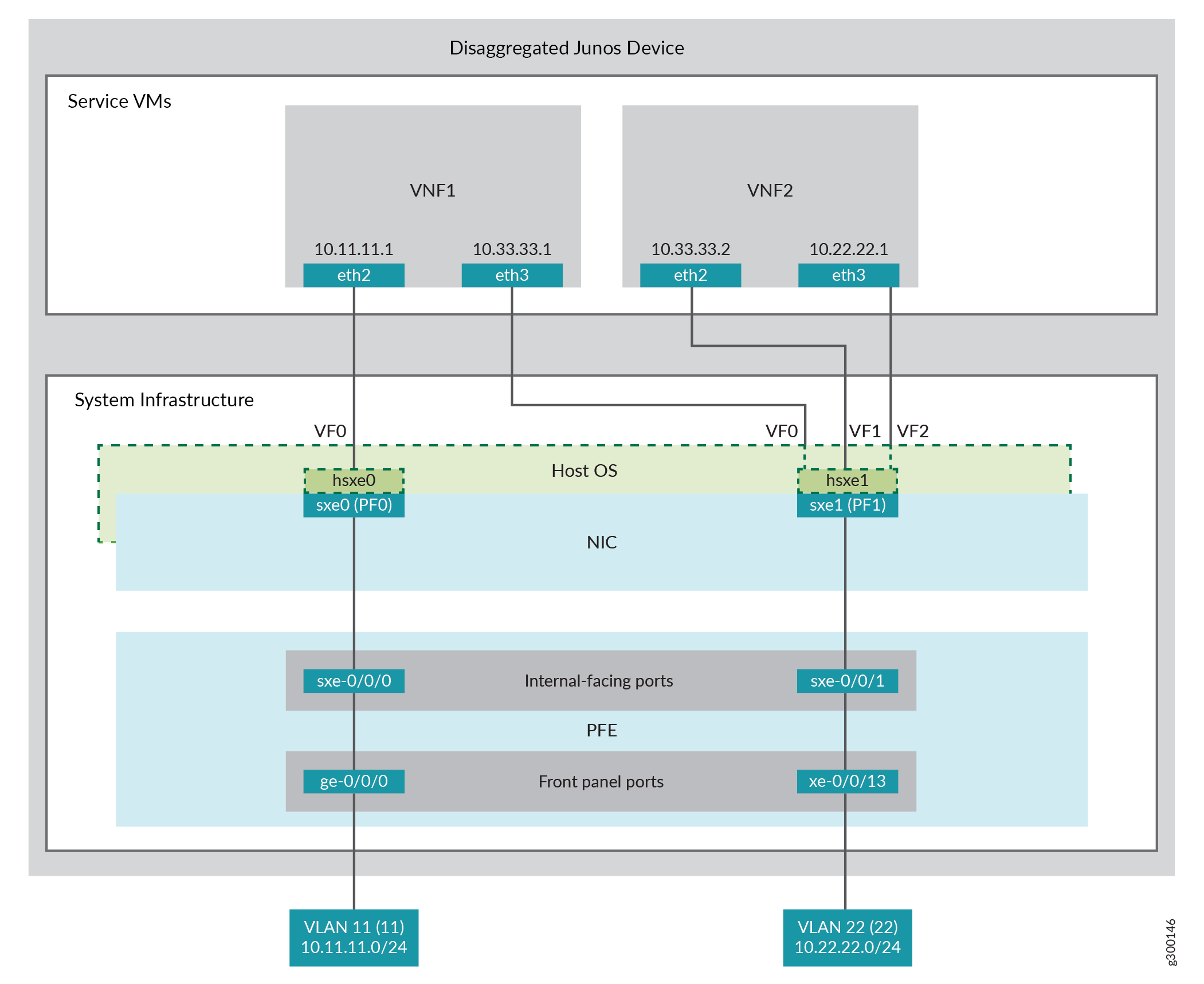
This example uses the front panel ports ge-0/0/0 and xe-0/0/13 associated with the PFE, and its internal-facing ports, sxe-0/0/0 and sxe-0/0/1. The internal NIC ports, sxe0 and sxe1, are not configured directly; instead, they are abstracted at the host OS layer and configured as interfaces hsxe0 and hsxe1. The VNFs use two interfaces, eth2 and eth3. These elements are generally separated into a LAN side and a WAN side.
As this example uses SR-IOV, the virtual functions (VFs) of the NIC ports are used to bypass the host OS and provide direct NIC-to-VM connectivity.
Topology
Figure 1 shows the topology for this example.
This example is configured using the Junos Control Plane (JCP). The key configuration elements include:
Front panel ports associated with the Packet Forwarding Engine
Internal-facing ports associated with the Packet Forwarding Engine
NIC ports
Note:You must use the host OS interface (hsxe) for these ports because the NIC interfaces (sxe ports) cannot be configured directly.
VNF interfaces, which use the format eth# (where # ranges from 2 to 9)
Virtual function settings, which indicate that SR-IOV is being used to provide direct access between the hsxe and VNF interfaces
Configuration
This example describes:
- Configuring the Packet Forwarding Engine Interfaces
- Configuring the VNF Interfaces and Creating the Service Chain
Configuring the Packet Forwarding Engine Interfaces
CLI Quick Configuration
To quickly configure the Packet Forwarding Engine interfaces, enter the following configuration statements from the JCP:
[edit]
user@host#

set vlans Vlan11 vlan-id 11
set interfaces ge-0/0/0.0 family ethernet-switching vlan member Vlan11
set interfaces sxe-0/0/0.0 family ethernet-switching interface-mode trunk
set interfaces sxe-0/0/0.0 family ethernet-switching vlan member Vlan11
set vlans Vlan22 vlan-id 22
set interfaces xe-0/0/13.0 family ethernet-switching interface-mode trunk
set interfaces xe-0/0/13.0 family ethernet-switching vlan member Vlan22
set interfaces sxe-0/0/1.0 family ethernet-switching interface-mode trunk
set interfaces sxe-0/0/1.0 family ethernet-switching vlan member Vlan22
Step-by-Step Procedure
To configure the Packet Forwarding Engine interfaces:
Configure a VLAN for the LAN-side interfaces.
user@host# set vlans Vlan11 vlan-id 11
Configure the PFE LAN-side front panel port and add it to the LAN-side VLAN.
The LAN-side port is typically an access port, but can be a trunk port if required.
user@host# set interfaces ge-0/0/0.0 family ethernet-switching vlan members Vlan11
Configure the PFE LAN-side internal-facing interface as a trunk port and add it to the LAN-side VLAN.
The internal-facing interfaces are typically trunk ports as they must support traffic from multiple front panel ports and VLANs.
user@host# set interfaces sxe-0/0/0.0 family ethernet-switching interface-mode trunk
user@host# set interfaces sxe-0/0/0.0 family ethernet-switching vlan member Vlan11
Configure a VLAN for the WAN-side interfaces.
user@host# set vlans Vlan22 vlan-id 22
Configure the PFE WAN-side front panel port as a trunk port and add it to the WAN-side VLAN.
The WAN-side front panel port is typically a trunk port as it might be required to support multiple VLANs.
user@host# set interfaces xe-0/0/13.0 family ethernet-switching interface-mode trunk
user@host# set interfaces xe-0/0/13.0 family ethernet-switching vlan members Vlan22
Configure the PFE WAN-side internal-facing interface as a trunk port and add it to the WAN-side VLAN.
user@host# set interfaces sxe-0/0/1.0 family ethernet-switching interface-mode trunk
user@host# set interfaces sxe-0/0/1.0 family ethernet-switching vlan members Vlan22
Commit the configuration.
user@host# commit
Results
From configuration mode, check the results of your configuration by entering the following show commands:
user@host> show interfaces ge-0/0/0
unit 0 {
    family ethernet-switching {
        vlan {
            members Vlan11;
        }
    }
}

user@host> show interfaces xe-0/0/13
unit 0 {
    family ethernet-switching {
        interface-mode trunk;
        vlan {
            members Vlan22;
        }
    }
}

user@host> show interfaces sxe-0/0/0
unit 0 {
    family ethernet-switching {
        interface-mode trunk;
        vlan {
            members Vlan11;
        }
    }
}

user@host> show interfaces sxe-0/0/1
unit 0 {
    family ethernet-switching {
        interface-mode trunk;
        vlan {
            members Vlan22;
        }
    }
}

user@host> show vlans
Vlan11 {
    vlan-id 11;
}
Vlan22 {
    vlan-id 22;
}
Configuring the VNF Interfaces and Creating the Service Chain
Step-by-Step Procedure
To configure the VNF interfaces and create the service chain:
Configure VNF1’s LAN-side interface as a Layer 3 interface, and map it to the LAN-side NIC interface. Include the virtual function (VF) setting to specify direct NIC-to-VM connectivity. VNFs must use the interfaces from eth2 through eth9.
The hsxe interface is the configurable representation of the related NIC (sxe) interface.
user@host> configure
[edit]
user@host# set virtual-network-functions vm1 interfaces eth2 mapping interface hsxe0 virtual-function
Configure VNF1’s WAN-side interface from sxe1.
user@host# set virtual-network-functions vm1 interfaces eth3 mapping interface hsxe1 virtual-function
Instantiate VNF2 with the interfaces eth2 and eth3 on sxe1.
user@host# set virtual-network-functions vm2 interfaces eth2 mapping interface hsxe1 virtual-function
user@host# set virtual-network-functions vm2 interfaces eth3 mapping interface hsxe1 virtual-function
Configure the IP addresses and static routes for each interface of the VNFs, and add routes to achieve a complete bidirectional path for the service chain.