Example: Configuring Cross-Connect on NFX250 NextGen Devices
This example shows how to configure the cross-connect feature on NFX250 NextGen devices.
Requirements
This example uses an NFX250 NextGen device running Junos OS Release 19.1R1.
Overview
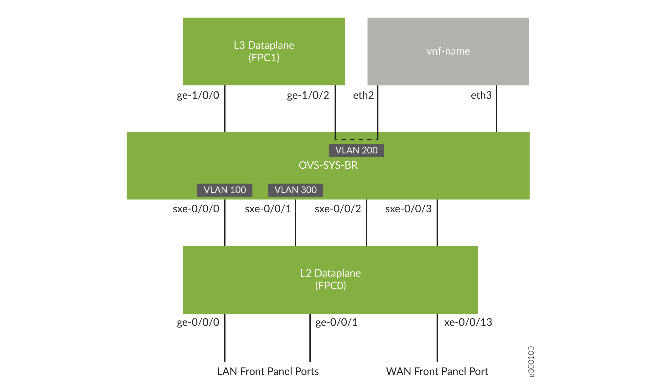
The cross-connect feature enables traffic switching between any two VNF interfaces. You can bidirectionally switch either all traffic or traffic belonging to a particular VLAN between any two VNF interfaces.
This feature does not support unidirectional traffic flow.
The cross-connect feature supports the following:
Port cross-connect between two VNF interfaces for all network traffic.
VLAN-based traffic forwarding between VNF interfaces that support the following functions:
Provides an option to switch traffic based on a VLAN ID.
Supports VLAN PUSH, POP, and SWAP operations.
Supports network traffic flow from trunk to access port through the POP operation.
Supports network traffic flow from access to trunk ports through the PUSH operation.
Configuration
- Configuring VLANs
- Configure the Layer 2 Datapath
- Configuring the Layer 3 Datapath
- Configuring the VNF
- Configuring Cross-Connect
Configuring VLANs
Step-by-Step Procedure
Configure VLANs for the LAN-side interfaces.
user@host# set vlans vlan100 vlan-id 100
Configure a VLAN for the WAN-side interface.
user@host# set vlans vlan300 vlan-id 300
Configure the Layer 2 Datapath
Step-by-Step Procedure
Configure the LAN-side front panel ports and add them to the LAN-side VLAN.
user@host# set interfaces ge-0/0/0 unit 0 family ethernet-switching interface-mode trunk
user@host# set interfaces ge-0/0/0 unit 0 family ethernet-switching vlan members vlan100
user@host# set interfaces ge-0/0/1 unit 0 family ethernet-switching interface-mode trunk
user@host# set interfaces ge-0/0/1 unit 0 family ethernet-switching vlan members vlan100
user@host# set interfaces sxe-0/0/0 unit 0 family ethernet-switching interface-mode trunk
user@host# set interfaces sxe-0/0/0 unit 0 family ethernet-switching vlan members vlan100
Configure the internal-facing interfaces as trunk ports and add them to the WAN-side VLAN. The internal-facing interfaces are typically trunk ports as they must support traffic from multiple front panel ports and VLANs.
user@host# set interfaces xe-0/0/13 unit 0 family ethernet-switching interface-mode trunk
user@host# set interfaces xe-0/0/13 unit 0 family ethernet-switching vlan members vlan300
user@host# set interfaces sxe-0/0/1 unit 0 family ethernet-switching interface-mode trunk
user@host# set interfaces sxe-0/0/1 unit 0 family ethernet-switching vlan members vlan300
Configuring the Layer 3 Datapath
Step-by-Step Procedure
Configure VLAN tagging on ge-1/0/0:
user@host# set interfaces ge-1/0/0 vlan-tagging
user@host# set interfaces ge-1/0/0 unit 0 vlan-id 100
user@host# set interfaces ge-1/0/0 unit 0 family inet address 192.0.2.1/24
Configure VLAN tagging on ge-1/0/2:
user@host# set interfaces ge-1/0/2 vlan-tagging
user@host# set interfaces ge-1/0/2 unit 0 vlan-id 200
user@host# set interfaces ge-1/0/2 unit 0 family inet address 203.0.113.2/24
Configuring the VNF
Step-by-Step Procedure
Launch the VNF:
user@host# set virtual-network-functions vnf-name image /var/public/centos-updated_1.img
user@host# set virtual-network-functions vnf-name image image-type raw
Specify the number of CPUs required for the VNF:
user@host# set virtual-network-functions vnf-name virtual-cpu count 1
Pin a virtual CPU to a physical CPU:
user@host# set virtual-network-functions vnf-name virtual-cpu 0 physical-cpu 2
Create host VLANs:
user@host# set vmhost vlans vlan200 vlan-id 200
user@host# set vmhost vlans vlan300 vlan-id 300
Configure the VNF interfaces as trunk ports and add them to the LAN-side VLAN:
user@host# set virtual-network-functions vnf-name interfaces eth2 mapping vlan mode trunk
user@host# set virtual-network-functions vnf-name interfaces eth2 mapping vlan members vlan200
user@host# set virtual-network-functions vnf-name interfaces eth3 mapping vlan members vlan300
Specify the memory allocation for the VNF:
user@host# set virtual-network-functions vnf-name memory size 1048576
Configuring Cross-Connect
Step-by-Step Procedure
Configure cross-connect:
user@host# set vmhost cross-connect c1 virtual-interface ge-1/0/2
user@host# set vmhost cross-connect c1 virtual-network-function vnf-name interface eth2
Verifying the Configuration
Verifying the Control Plane Configuration
Purpose
Verify the control plane configuration:
Action
Verify the VLANs configured.
user@host > show vlans
Routing instance        VLAN name             Tag          Interfaces
default-switch          default               1

default-switch          vlan100               100
                                                           ge-0/0/0.0*
                                                           ge-0/0/1.0*
                                                           sxe-0/0/0.0*
default-switch          vlan200               200
                                                           sxe-0/0/1.0*
                                                           xe-0/0/12.0*
default-switch          vlan300               300
                                                           sxe-0/0/1.0*
                                                           xe-0/0/13.0*
Verify that the VLANs and VLAN memberships are correct by using the
show vmhost vlanscommand.user@host> show vmhost vlans Routing instance VLAN name Tag Interfaces vmhost vlan200 200 vnf-name_eth2.0 vmhost vlan300 300 vnf-name_eth3.0Verify that the VNF is operational. The
Statefield showsRunningfor VNFs that are up.user@host> show virtual-network-functions vnf-name ID Name State Liveliness -------------------------------------------------------------------------------- 3 vnf-name Running alive
The
Livelinessfield of the VNF indicates whether the internal management IP address of the VNF is accessible from the Junos Control Plane (JCP).To view more details of the VNF:
user@host> show virtual-network-functions vnf-name detail
Virtual Network Function Information
------------------------------------

Id:                 3
Name:               vnf-name
State:              Running
Liveliness:         alive
IP Address:         192.0.2.100
VCPUs:              1
Maximum Memory:     1048576 KiB
Used Memory:        1048576 KiB
Used 1G Hugepages:  0
Used 2M Hugepages:  0
Error:              None
Verifying the Data Plane Configuration
Purpose
Verify the data plane configuration.
Action
Verify the status of the Layer 2 (ge-0/0/x) and Layer 3 (ge-1/0/x) interfaces.
user@host> show interfaces interface-name statistics
For example:
user@host> show interfaces ge-0/0/0 statistics Physical interface: ge-0/0/0, Enabled, Physical link is Up Interface index: 149, SNMP ifIndex: 517 Link-level type: Ethernet, MTU: 1514, LAN-PHY mode, Link-mode: Full-duplex, Speed: 1000mbps, Duplex: Full-Duplex, BPDU Error: None, Loop Detect PDU Error: None, Ethernet-Switching Error: None, MAC-REWRITE Error: None, Loopback: Disabled, Source filtering: Disabled, Flow control: Enabled, Auto-negotiation: Enabled, Remote fault: Online, IEEE 802.3az Energy Efficient Ethernet: Disabled, Auto-MDIX: Enabled Device flags : Present Running Interface flags: SNMP-Traps Internal: 0x4000 Link flags : None CoS queues : 12 supported, 12 maximum usable queues Current address: 30:7c:5e:4c:78:03, Hardware address: 30:7c:5e:4c:78:03 Last flapped : 2018-11-26 11:03:32 UTC (04:15:32 ago) Input rate : 0 bps (0 pps) Output rate : 0 bps (0 pps) Active alarms : None Active defects : None PCS statistics Seconds Bit errors 0 Errored blocks 0 Ethernet FEC statistics Errors FEC Corrected Errors 0 FEC Uncorrected Errors 0 FEC Corrected Errors Rate 0 FEC Uncorrected Errors Rate 0 PRBS Statistics : Disabled Interface transmit statistics: Disabled Logical interface ge-0/0/0.0 (Index 330) (SNMP ifIndex 519) Flags: Up SNMP-Traps 0x24024000 Encapsulation: Ethernet-Bridge Input packets : 0 Output packets: 0 Protocol eth-switch, MTU: 1514 Flags: Trunk-Modeuser@host> show interfaces ge-1/0/2 statistics Physical interface: ge-1/0/2, Enabled, Physical link is Up Interface index: 167, SNMP ifIndex: 547 Link-level type: Ethernet, MTU: 1518, LAN-PHY mode, Link-mode: Half-duplex, Speed: 1000mbps, BPDU Error: None, Loop Detect PDU Error: None, Ethernet-Switching Error: None, MAC-REWRITE Error: None, Loopback: Disabled, Source filtering: Disabled, Flow control: Enabled, Auto-negotiation: Enabled, Remote fault: Online Device flags : Present Running Interface flags: SNMP-Traps Internal: 0x4000 CoS queues : 8 supported, 8 maximum usable queues Current address: 30:7c:5e:4c:78:1d, Hardware address: 30:7c:5e:4c:78:1d Last flapped : 2018-11-26 11:03:45 UTC (04:19:57 ago) Input rate : 0 bps (0 pps) Output rate : 0 bps (0 pps) Active alarms : None Active defects : None PCS statistics Seconds Bit errors 0 Errored blocks 0 Ethernet FEC statistics Errors FEC Corrected Errors 0 FEC Uncorrected Errors 0 FEC Corrected Errors Rate 0 FEC Uncorrected Errors Rate 0 PRBS Statistics : Disabled Interface transmit statistics: Disabled Logical interface ge-1/0/2.0 (Index 334) (SNMP ifIndex 550) Flags: Up SNMP-Traps 0x4000 VLAN-Tag [ 0x8100.200 ] Encapsulation: ENET2 Input packets : 0 Output packets: 0 Security: Zone: Null Protocol inet, MTU: 1500 Max nh cache: 75000, New hold nh limit: 75000, Curr nh cnt: 0, Curr new hold cnt: 0, NH drop cnt: 0 Flags: Sendbcast-pkt-to-re Addresses, Flags: Is-Preferred Is-Primary Destination: 203.0.113/24, Local: 203.0.113.2, Broadcast: 203.0.113.255 Logical interface ge-1/0/2.32767 (Index 335) (SNMP ifIndex 551) Flags: Up SNMP-Traps 0x4004000 VLAN-Tag [ 0x0000.0 ] Encapsulation: ENET2 Input packets : 0 Output packets: 0 Security: Zone: NullVerify the status of the OVS interfaces.
user@host> show vmhost network nfv-back-plane
Network Name : ovs-sys-br

   Interface : ovs-sys-br
   Type : internal, Link type : Full-Duplex, MAC : 52:86:3c:df:9c:44
   MTU : [], Link State :down, Admin State : down
   IPV4 : None, Netmask : None
   IPV6 : None, IPV6 netmask : None
       Rx-packets :       0
       Rx-drops   :       0
       Rx-errors  :       0
       Tx-packets :       1
       Tx-drops   :       1
       Tx-errors  :       0

   Interface : dpdk0
   Type : dpdk, Link type : Full-Duplex, MAC : 02:09:c0:e2:b9:08
   MTU : [], Link State :up, Admin State : up
   IPV4 : None, Netmask : None
   IPV6 : None, IPV6 netmask : None
       Rx-packets :       0
       Rx-drops   :       0
       Rx-errors  :       0
       Tx-packets :       1
       Tx-drops   :       0
       Tx-errors  :       0

   Interface : dpdk1
   Type : dpdk, Link type : Full-Duplex, MAC : 02:09:c0:83:39:72
   MTU : [], Link State :up, Admin State : up
   IPV4 : None, Netmask : None
   IPV6 : None, IPV6 netmask : None
       Rx-packets :       0
       Rx-drops   :       0
       Rx-errors  :       0
       Tx-packets :       0
       Tx-drops   :       0
       Tx-errors  :       0

   Interface : l3_h_ge_1_0_0
   Type : dpdkvhostuser, Link type : Full-Duplex, MAC : 00:00:00:00:00:00
   MTU : [], Link State :up, Admin State : up
   IPV4 : None, Netmask : None
   IPV6 : None, IPV6 netmask : None
       Rx-packets :       0
       Rx-drops   :       0
       Rx-errors  :       0
       Tx-packets :       0
       Tx-drops   :       0
       Tx-errors  :       0

   Interface : l3_h_ge_1_0_2
   Type : dpdkvhostuser, Link type : Full-Duplex, MAC : 00:00:00:00:00:00
   MTU : [], Link State :down, Admin State : up
   IPV4 : None, Netmask : None
   IPV6 : None, IPV6 netmask : None
       Rx-packets :       0
       Rx-drops   :       0
       Rx-errors  :       0
       Tx-packets :       0
       Tx-drops   :       0
       Tx-errors  :       0

   Interface : vnf-name_eth2
   Type : dpdkvhostuser, Link type : Full-Duplex, MAC : 00:00:00:00:00:00
   MTU : 1500, Link State :down, Admin State : up
   IPV4 : None, Netmask : None
   IPV6 : None, IPV6 netmask : None
       Rx-packets :       0
       Rx-drops   :       0
       Rx-errors  :       0
       Tx-packets :       0
       Tx-drops   :       0
       Tx-errors  :       0

   Interface : vnf-name_eth3
   Type : dpdkvhostuser, Link type : Full-Duplex, MAC : 00:00:00:00:00:00
   MTU : 1500, Link State :down, Admin State : up
   IPV4 : None, Netmask : None
   IPV6 : None, IPV6 netmask : None
       Rx-packets :       0
       Rx-drops   :       0
       Rx-errors  :       0
       Tx-packets :       0
       Tx-drops   :       0
       Tx-errors  :       0