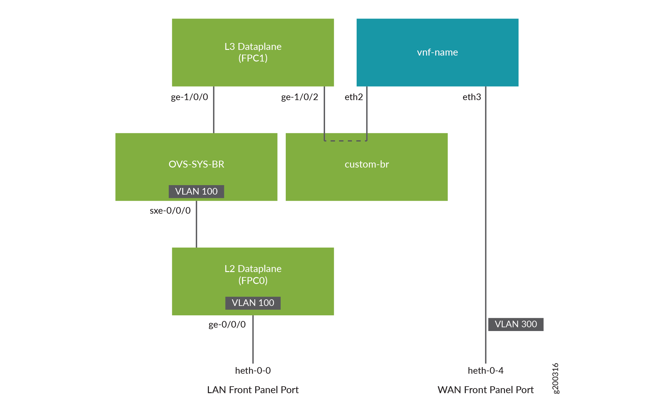
Example: Configuring Cross-Connect Using a Custom Bridge on NFX150 Devices
This example shows how to configure cross-connect using a custom bridge on NFX150 devices.
Requirements
This example uses the following hardware and software components:
NFX150 running Junos OS Release 18.1R1
Overview
The Cross-connect feature enables traffic switching between any two VNF interfaces. You can bidirectionally switch either all traffic or traffic belonging to a particular VLAN between any two VNF interfaces.
This feature does not support unidirectional traffic flow.
The Cross-connect feature supports the following:
Port cross-connect between two VNF interfaces for all network traffic.
VLAN-based traffic forwarding between VNF interfaces that support the following functions:
Provides an option to switch traffic based on a VLAN ID.
Supports network traffic flow from trunk to access port through POP operation.
Supports network traffic flow from access to trunk port through PUSH operation.
Supports VLAN PUSH, POP, and SWAP operations.
Configuration
- Create VLANs
- Map the Interfaces
- Configure the Layer 2 Datapath
- Configure the Layer 3 Datapath
- Configure the VNF
- Configure Cross-Connect
Create VLANs
Step-by-Step Procedure
Configure VLANs for the LAN-side interfaces.
user@host# set vlans vlan100 vlan-id 100
Map the Interfaces
Step-by-Step Procedure
Map the heth-0-0 physical port to the FPC0 interface.
user@host# set vmhost virtualization-options interfaces ge-0/0/0 mapping interface heth-0-0
Create the custom bridge.
user@host# set vmhost vlans custom-br vlan-id none
Map the FPC1 interface ge-1/0/2 to the custom bridge.
user@host# set vmhost virtualization-options interfaces ge-1/0/2 mapping vlan custom-br
Configure the Layer 2 Datapath
Step-by-Step Procedure
Configure the LAN-side front panel ports and add them to the LAN-side VLAN.
user@host# set interfaces ge-0/0/0 unit 0 family ethernet-switching interface-mode trunk
user@host# set interfaces ge-0/0/0 unit 0 family ethernet-switching vlan members vlan100
Configure the internal-facing interfaces as trunk ports and add them to the LAN-side VLAN. The internal-facing interfaces are typically trunk ports, as they must support traffic from multiple front panel ports and VLANs.
user@host# set interfaces sxe-0/0/0 unit 0 family ethernet-switching interface-mode trunk
user@host# set interfaces sxe-0/0/0 unit 0 family ethernet-switching vlan members vlan100
Configure the Layer 3 Datapath
Step-by-Step Procedure
Configure VLAN tagging on ge-1/0/0:
user@host# set interfaces ge-1/0/0 vlan-tagging
user@host# set interfaces ge-1/0/0 unit 0 vlan-id 100
user@host# set interfaces ge-1/0/0 unit 0 family inet address 192.0.3.1/24
Configure VLAN tagging on ge-1/0/2:
user@host# set interfaces ge-1/0/2 vlan-tagging
user@host# set interfaces ge-1/0/2 unit 0 vlan-id 200
user@host# set interfaces ge-1/0/2 unit 0 family inet address 203.0.113.2/24
Configure the VNF
Step-by-Step Procedure
Launch the VNF:
user@host# set virtual-network-functions vnf-name image /var/public/centos-updated1.img
user@host# set virtual-network-functions vnf-name image image-type raw
Specify the number of CPUs required for the VNF:
user@host# set virtual-network-functions vnf-name virtual-cpu count 1
Pin a virtual CPU to a physical CPU:
user@host# set virtual-network-functions vnf-name virtual-cpu 0 physical-cpu 2
Create a VNF interface on the custom OVS bridge:
user@host# set virtual-network-functions vnf-name interfaces eth2 mapping vlan members custom-br
Attach a VNF interface to a physical interface by using the SR-IOV virtual function:
user@host# set virtual-network-functions vnf-name interfaces eth3 mapping interface heth-0-4 virtual-function vlan-id 300
Specify the memory allocation for the VNF:
user@host# set virtual-network-functions memory size 1048576
Configure Cross-Connect
Step-by-Step Procedure
Configure cross-connect:
user@host# set vmhost cross-connect c1 virtual-interface ge-1/0/2
user@host# set vmhost cross-connect c1 virtual-network-function vnf-name interface eth2
Verifying the Configuration
Verify the Control Plane Configuration
Purpose
Verify the control plane configuration:
Action
To verify the control plane configuration:
Verify that the VLANs and VLAN memberships are correct by using the
show vmhost vlanscommand.user@host> show vmhost vlans Routing instance VLAN name Tag Interfaces vmhost custom-br ge-1/0/2.0Verify that the VNF is operational. View the status of the VNF to ensure that the VNF is up and running.
user@host# show virtual-network-functions vnf-name
ID       Name                                              State      Liveliness
--------------------------------------------------------------------------------
2        vnf-name                                           Running    alive
The
Livelinessoutput field of the VNF indicates whether the IP address of the VNF is reachable or not reachable from Junos.To view more details of the VNF:
user@host# show virtual-network-functions VNF detail
Virtual Network Function Information
------------------------------------

Id:                 2
Name:               vnf-name
State:              Running
Liveliness:         Up
IP Address:         192.0.2.101
VCPUs:              1
Maximum Memory:     1048576 KiB
Used Memory:        1048576 KiB
Used 1G Hugepages:  0
Used 2M Hugepages:  0
Error:              None
Verify the Data Plane Configuration
Purpose
Verify the data plane configuration.
Action
To verify the data plane configuration:
Verify the status of the physical ports.
user@host> show interfaces heth-0-0 statistics
Physical interface: heth-0-0, Enabled, Physical link is Up
  Link-level type: Ethernet, Media type: Copper, MTU: 9192, Speed: 1Gbps, Duplex: Full-duplex, Auto-negotiation: Enabled
  Device flags   : Present Running
  Current address: 00:00:5e:00:53:8d, Hardware address: 00:00:5e:00:53:8d
    Input packets : 311143
    Output packets: 674
  MAC statistics:
    Input bytes: 19913152, Input packets: 311143, Output bytes: 48658, Output packets: 674
  VF statistics:
    VF Number: 0, PCI Address: 0000:02:10:1, Mapped to: ge-0/0/0
      Input bytes: 19909120, Input packets: 311080, Output bytes: 48658, Output packets: 674, Multicast packets: 311080
    VF Number: 1, PCI Address: 0000:02:10:5, Mapped to: ge-0/0/0
      Input bytes: 0, Input packets: 0, Output bytes: 0, Output packets: 0, Multicast packets: 0
    VF Number: 2, PCI Address: 0000:02:11:1, Mapped to: ge-0/0/0
      Input bytes: 0, Input packets: 0, Output bytes: 0, Output packets: 0, Multicast packets: 0
    VF Number: 3, PCI Address: 0000:02:11:5, Mapped to: ge-0/0/0
      Input bytes: 0, Input packets: 0, Output bytes: 0, Output packets: 0, Multicast packets: 0
Verify the status of the Layer 2 (ge-0/0/x) and Layer 3 (ge-1/0/x) interfaces.
user@host > show interfaces interface-name statistics
For example:
user@host > show interfaces ge-0/0/0 statistics Physical interface: ge-0/0/0, Enabled, Physical link is Up Interface index: 144, SNMP ifIndex: 518 Link-level type: Ethernet, MTU: 9192, LAN-PHY mode, Speed: 1000mbps, BPDU Error: None, Loop Detect PDU Error: None, Ethernet-Switching Error: None, MAC-REWRITE Error: None, Loopback: Disabled, Source filtering: Disabled, Flow control: Enabled Device flags : Present Running Interface flags: SNMP-Traps Internal: 0x4000 Link flags : None CoS queues : 8 supported, 8 maximum usable queues Current address: 00:00:5e:00:53:43, Hardware address: 00:00:5e:00:53:43 Last flapped : 2018-04-18 05:38:22 UTC (6d 00:28 ago) Statistics last cleared: Never Input rate : 0 bps (0 pps) Output rate : 0 bps (0 pps) Input errors: 0, Output errors: 0 Active alarms : None Active defects : None PCS statistics Seconds Bit errors 0 Errored blocks 0 Ethernet FEC statistics Errors FEC Corrected Errors 0 FEC Uncorrected Errors 0 FEC Corrected Errors Rate 0 FEC Uncorrected Errors Rate 0 PRBS Statistics : Disabled Interface transmit statistics: Disabled Logical interface ge-0/0/0.0 (Index 333) (SNMP ifIndex 524) Flags: Up SNMP-Traps 0x24024000 Encapsulation: Ethernet-Bridge Input packets : 311115 Output packets: 22 Protocol eth-switch, MTU: 9192 Flags: Trunk-Modeuser@host > show interfaces ge-1/0/2 statistics Physical interface: ge-1/0/2, Enabled, Physical link is Up Interface index: 158, SNMP ifIndex: 536 Link-level type: Ethernet, MTU: 1518, LAN-PHY mode, Link-mode: Full-duplex, Speed: 1000mbps, BPDU Error: None, Loop Detect PDU Error: None, Ethernet-Switching Error: None, MAC-REWRITE Error: None, Loopback: Disabled, Source filtering: Disabled, Flow control: Enabled, Auto-negotiation: Enabled, Remote fault: Online Device flags : Present Running Interface flags: SNMP-Traps Internal: 0x4000 CoS queues : 8 supported, 8 maximum usable queues Current address: 00:00:5e:00:53:5d, Hardware address: 00:00:5e:00:53:5d Last flapped : 2018-04-23 06:03:29 UTC (1d 00:04 ago) Statistics last cleared: Never Input rate : 0 bps (0 pps) Output rate : 0 bps (0 pps) Input errors: 0, Output errors: 0 Active alarms : None Active defects : None PCS statistics Seconds Bit errors 0 Errored blocks 0 Ethernet FEC statistics Errors FEC Corrected Errors 0 FEC Uncorrected Errors 0 FEC Corrected Errors Rate 0 FEC Uncorrected Errors Rate 0 PRBS Statistics : Disabled Interface transmit statistics: Disabled Logical interface ge-1/0/2.0 (Index 342) (SNMP ifIndex 538) Flags: Up SNMP-Traps 0x4000 VLAN-Tag [ 0x8100.200 ] Encapsulation: ENET2 Input packets : 0 Output packets: 0 Security: Zone: untrust Allowed host-inbound traffic : dns dhcp tftp https Protocol inet, MTU: 1500 Max nh cache: 75000, New hold nh limit: 75000, Curr nh cnt: 0, Curr new hold cnt: 0, NH drop cnt: 0 Flags: Sendbcast-pkt-to-re Addresses, Flags: Is-Preferred Is-Primary Destination: 203.0.113/24, Local: 203.0.113.2, Broadcast: 203.0.113.255 Protocol multiservice, MTU: Unlimited Logical interface ge-1/0/2.32767 (Index 343) (SNMP ifIndex 545) Flags: Up SNMP-Traps 0x4004000 VLAN-Tag [ 0x0000.0 ] Encapsulation: ENET2 Input packets : 0 Output packets: 0 Security: Zone: Null Protocol multiservice, MTU: Unlimited Flags: None