NFX150 Feature Overview
Software Architecture
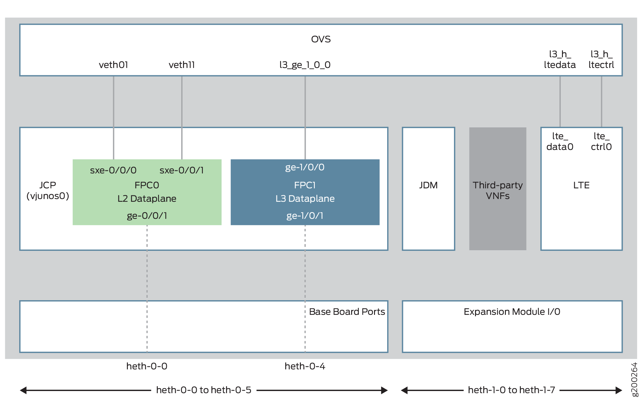
The software architecture for the NFX150 is designed to provide a unified control plane that functions as a single management point.
Figure 1 illustrates the architecture of the NFX150.
Key components of the system software include:
-
VNF—A VNF is a consolidated offering that contains all the components required for supporting a fully virtualized networking environment. You can configure and use third-party VNFs in service chains.
-
Junos Control Plane (JCP)—The JCP is the Junos VM running on the host OS, Wind River Linux. The JCP functions as the single point of management for all the components. The JCP controls the Layer 2 dataplane, which provide the Layer 2 services and the Layer 3 dataplane, which provides the Layer 3 to Layer 7 services.
In addition to chassis management, JCP enables:
-
Configuration of advanced security features.
-
Management of guest virtualized network functions (VNFs) during their life cycle.
-
Installation of third-party VNFs.
-
Creation of VNF service chains.
-
Management of guest VNF images (their binary files).
-
Management of the system inventory and resource usage.
-
Management of the LTE interface.
-
-
Juniper Device Manager (JDM)—An application container that manages VNFs and provides infrastructure services. The JDM functions in the background and users cannot access JDM directly.
-
L2 Dataplane—The Layer 2 dataplane that manages the Layer 2 traffic. The Layer 2 dataplane forwards the LAN traffic to the NFV backplane, Open vSwitch (OVS). The Layer 2 dataplane is mapped to the virtual FPC0 on the JCP. By default, all the 1-Gigabit Ethernet physical ports are mapped to the virtual interfaces on the Layer 2 dataplane.
-
L3 Dataplane—The Layer 3 dataplane that provides datapath functions for the Layer 3 to Layer 7 services. The Layer 3 dataplane is mapped to the virtual FPC1 on the JCP. By default, the two SFP+ ports on the NFX150 chassis are mapped to the virtual interfaces on the Layer 3 dataplane.
-
Linux—The host OS, WindRiver Linux. In Junos OS Release 18.1R1, the WindRiver Linux version is 8.
-
Open vSwitch (OVS) bridge—The OVS bridge is a VLAN-aware system bridge, which acts as the NFV backplane to which the VNFs and FPCs connect. Additionally, you can create custom OVS bridges to isolate connectivity between different VNFs.
-
LTE—A containerized driver that provides 4G LTE connectivity management. The LTE container is bound to the FPC1 for management.
Interfaces
The interfaces on the NFX150 devices comprise of physical interfaces, virtual interfaces, and the LTE interface.
Physical Interfaces
The physical interfaces represent the physical ports on the NFX150 chassis and expansion module. The physical interfaces comprise of network and management ports:
Network ports—Four 1-Gigabit Ethernet ports and two 10-Gigabit Ethernet SFP+ ports function as network ports on the NFX150 chassis. The expansion modules consists of six 1-Gigabit Ethernet ports and two 1-Gigabit Ethernet SFP ports.
The network ports follow the naming convention heth-slot number-port number, where:
heth denotes host Ethernet
slot number is 0 for the chassis ports and 1 for the expansion module ports. The ports on the chassis are named as heth-0-x and the ports on the expansion module are named heth-1-x.
port number is the number of the port on the chassis or expansion module
Each physical port has four virtual functions (VFs) enabled by default.
Note:You cannot map a VF from a port which is mapped to the Layer 2 dataplane.
Management port—The NFX150 device has a dedicated management port labeled MGMT (fxp0), which functions as the out-of-band management interface. The fxp0 interface is assigned an IP address in the 192.168.1.1/24 network.
Virtual Interfaces
The virtual FPCs running within the JCP, contain the virtual interfaces. The virtual interfaces on the NFX150 devices are categorized as follows:
Virtual Layer 2 interfaces (FPC0)—Denoted as ge-0/0/x, where the value of x ranges from:
0 to 3 for NFX150 devices without an expansion module
0 to 11 for NFX150 devices with an expansion module
These interfaces are used to configure the following Ethernet switching features:
Layer 2 switching of traffic, including support for both trunk and access ports
Link Layer Discovery Protocol (LLDP)
IGMP snooping
Port Security features (MAC limiting, Persistent MAC learning)
MVRP
Ethernet OAM, CFM, and LFM
All the 1-Gigabit Ethernet physical ports (heth ports) are mapped to FPC0, by default.
Virtual Layer 3 interfaces (FPC1)—Denoted as ge-1/0/x, where value of x ranges from 0 to 9. These interfaces are used to configure Layer 3 features such as routing protocols and QoS.
In an NFX150 device, you can configure any of the ge-1/0/x interfaces as in-band management interfaces. In in-band management, you configure a network interface as a management interface and connect it to the management device. You can configure any number of interfaces for in-band management by assigning an IPv4 or IPv6 address to each of the ports, and an in-band management VLAN.
Note:The NFX150 devices do not support integrated routing and bridging (IRB) interfaces. The IRB functionality is provided by ge-1/0/0, which is always mapped to the service chaining backplane (OVS). Note that this mapping cannot be changed.
Virtual SXE Interfaces—Two static interfaces, sxe-0/0/0 and sxe-0/0/1, connect the FPC0 (Layer 2 dataplane) to the OVS backplane.
LTE Interface
The NFX150 device models with LTE support can be configured for wireless WAN connectivity over 3G or 4G networks. The LTE physical interface uses the name cl-1/1/0. The dialer interface, dl0, is a logical interface, which is used to trigger calls.
Interface Mapping
Table 1 summarizes the interfaces on the NFX150.
Interface Name |
Description |
|---|---|
heth-0-0 to heth-0-5 |
Physical ports on the front panel of the NFX150 device, which can be mapped to Layer 2 or Layer 3 interfaces, or VNFs. Ports heth-0-0 to heth-0-3 are 10 Mbps/100 Mbps/1 Gbps tri-speed copper ports. Ports heth-0-4 and heth-0-5 are 10 Gbps SFP+ ports For Junos OS Releases 18.1, 18.2 R1, and 18.3 R1:
For Junos OS Release 18.2 R2
Ports heth-0-3 and heth-0-5 are mapped to the WAN ports ge-1/0/1 and ge-1/0/2, respectively. |
heth-1-0 to heth-1-7 |
Physical ports on the expansion module of the NFX150-S1 device. These ports are mapped to the ge-0/0/n ports by default. Ports heth-1-0 to heth-1-5 are 10 Mbps/100 Mbps/1 Gbps tri-speed copper ports mapped to the LAN ports ge-0/0/4 to ge-0/0/9, respectively. Ports heth-1-6 and heth-1-7 are 1 Gbps SFP ports mapped to the LAN ports ge-0/0/10 and ge-0/0/11 respectively. |
ge-0/0/x |
Logical Layer 2 interfaces, which can be used for LAN connectivity. The values of x ranges from:
|
ge-1/0/x |
A set of up to 10 logical Layer 3 interfaces. Each of these interfaces can have 4k sub-interfaces. The value of x ranges from 0 to 9. |
cl-1/1/0 |
The LTE cellular interface, which carries the physical layer attributes. |
dl0 |
The LTE dialer interface, which carries Layer 3 and security services. The security flow session contains the dl0 interface as the ingress or egress interface. |
st0 |
Secure tunnel interface used for IPsec VPNs. |
fxp0 |
The out-of-band management interface. |
The list of supported transceivers for the NFX150 is located at https://pathfinder.juniper.net/hct/product/.
Table 3 illustrates the default mapping between the physical and virtual interfaces on a NFX150 device.
Physical Port |
Virtual Interface (Layer 2 dataplane) |
Virtual Interface (Layer 3 dataplane) |
|---|---|---|
heth-0-0 |
ge-0/0/0 |
NA |
heth-0-1 |
ge-0/0/1 |
NA |
heth-0-2 |
ge-0/0/2 |
NA |
heth-0-3 |
ge-0/0/3 |
NA |
heth-0-4 |
NA |
ge-1/0/1 |
heth-0-5 |
NA |
ge-1/0/2 |
Physical Port |
Virtual Interface (Layer 2 dataplane) |
Virtual Interface (Layer 3 dataplane) |
|---|---|---|
heth-0-0 |
ge-0/0/0 |
NA |
heth-0-1 |
ge-0/0/1 |
NA |
heth-0-2 |
ge-0/0/2 |
NA |
heth-0-3 |
NA |
ge-1/0/1 |
heth-0-4 |
ge-0/0/3 |
NA |
heth-0-5 |
NA |
ge-1/0/2 |
Table 4 illustrates the default mapping between the physical ports on the expansion module and the virtual interfaces.
Physical Port |
Virtual Port (Layer 2 dataplane) |
|---|---|
heth-1-0 |
ge-0/0/4 |
heth-1-1 |
ge-0/0/5 |
heth-1-2 |
ge-0/0/6 |
heth-1-3 |
ge-0/0/7 |
heth-1-4 |
ge-0/0/8 |
heth-1-5 |
ge-0/0/9 |
heth-1-6 |
ge-0/0/10 |
heth-1-7 |
ge-0/0/11 |
The expansion module ports are mapped to the Layer 2 dataplane interfaces by default. You can change the mapping to suit your requirement. Any of the ports on the chassis and expansion module can be mapped to the ge-1/0/x or ge-0/0/x interfaces. Any change in port mapping configuration will automatically reset the affected FPC.
Supported Features
Table 5 lists the Junos features supported on NFX150.
Junos OS Release |
Routing |
Security |
Switching |
|---|---|---|---|
18.1R1 |
|
|
|
18.2 R1 |
|
For more details on supported features, see Feature Explorer.
Performance Modes
NFX150 devices provide the following operational modes:
-
Throughput mode—Provides maximum resources (CPU and memory) for Junos software and remaining resources, if any, for third-party VNFs.
Note:You cannot create VNFs in throughput mode.
Starting in Junos OS Release 21.1R1, mapping OVS to Layer 3 data plane interface is not supported in throughput mode on NFX150-S1 and NFX150-S1E devices. If the OVS mapping is present in releases prior to Junos OS Release 21.1R1, you must change the mapping before upgrading the device to Junos OS Release 21.1R1 to prevent a configuration commit failure.
-
Hybrid mode—Provides a balanced distribution of resources between the Junos software and third-party VNFs.
-
Compute mode—Provides minimal resources for Junos software and maximum resources for third-party VNFs.
-
Custom mode—Provides an option to allocate resources to the system components:
-
Layer 2 data plane, Layer 3 data plane, and NFV backplane for NFX150-S1 and NFX150-S1E models
-
Layer 2 data plane and Layer 3 data plane for NFX150-C-S1, NFX150-C-S1-AE/AA, and NFX150-C-S1E-AE/AA models
Note:Compute, hybrid, and throughput modes are supported in Junos OS Release 19.1R1 or later. Custom mode is supported starting in Junos OS Release 22.1R1.
The default mode is throughput in Junos OS Releases prior to 21.4R1. Starting in Junos OS Release 21.4R1, the default mode is compute. -
In hybrid and compute modes, you can map Layer 3 data plane interfaces to either SR-IOV or OVS. In throughput mode, you can map Layer 3 data plane interfaces to only SR-IOV.
For example:
Map Layer 3 data plane interfaces to SR-IOV:
user@host#set vmhost virtualization-options interfaces ge-1/0/1 mapping interface heth-0-1Map Layer 3 data plane interfaces to OVS:
user@host#set vmhost virtualization-options interfaces ge-1/0/1
In hybrid or compute mode, you can create VNFs using the available CPUs on each mode.
You can check the CPU availability by using the show vmhost mode
command.
Each VNF supports a maximum of 10 interfaces (eth0 through eth9), including the two
management interfaces eth0 and
eth1.
You cannot attach a single VNF interface to both SR-IOV and OVS. However, you can attach different interfaces from the same VNF to SR-IOV and OVS.
When the mapping to a particular Layer 3 data plane interface changes between SR-IOV NICs (for example, heth-0-0) or from heth-x-x to OVS or vice versa, then FPC1 restarts automatically.
To change the current mode, run the request vmhost mode mode-name
command. The request vmhost mode ? command lists only the
pre-defined modes such as hybrid, compute, and throughput modes.
Before switching to a mode, issue the show system visibility cpu and
show vmhost mode commands to check the availability of CPUs.
When switching between operational modes, ensure that resource and configuration
conflicts do not occur. For example, if you move from compute mode that supports
VNFs to throughput mode that does not support VNFs, conflicts occur:
user@host# run request vmhost mode throughput
error: Mode cannot be changed; Reason: No CPUs are available for VNFs in the desired mode, but there is atleast one VNF currently configured
If the Layer 3 data plane is not mapped to SR-IOV, then switching from hybrid or compute mode to throughput mode results in an error.
If you pin a virtual CPU to physical CPUs for a VNF, then ensure that the physical CPUs do not overlap with the CPUs being used for Juniper system components, including the physical CPU 0.
Physical CPUs used to pin an emulator can overlap with the CPUs being used for Juniper system components, except the physical CPU 0. This overlap can impact the performance of one or more Juniper system components and VNFs.
How to Define a Custom Mode Template
You can use a custom mode template if you need to allocate maximum resources to third-party VNFs. In custom mode, you must configure both CPU count and amount of memory for:
-
Layer 2 data plane, Layer 3 data plane, and NFV backplane for NFX150-S1 and NFX150-S1E models
-
Layer 2 data plane and Layer 3 data plane for NFX150-C-S1, NFX150-C-S1-AE/AA, NFX150-C-S1E-AE/AA models
The absence of any of the configuration causes a commit failure.
You can opt to disable the Layer 2 data plane to free up CPU and memory resources in deployments that do not require Layer 2 software PFE services.
user@host# set vmhost mode custom custom-mode-name layer-2-infrastructure offline
If you disable the the Layer 2 data plane, you cannot configure the virtual interface mappings of the Layer 2 dataplane. For example:
set vmhost virtualization-options interfaces ge-0/0/0 mapping interface heth-0-0
Before you configure custom mode, note the following:
-
If you disable the Layer 2 dataplane, then you cannot configure
cpu countandmemory sizefor the Layer 2 dataplane.If you do not disable the Layer 2 dataplane, then you must configure the
cpu countandmemory sizefor it. The CPU count and memory must not exceed the total CPU count and memory available on the system. -
You can opt to configure the CPU quota for the Layer 3 data plane by using the
set vmhost mode custom
                                    custom-mode-name layer-3-infrastructure cpu
                                colocation quota quota-value
command, where quota-value can range from 1 through 99. If you configurecpu colocation quota, then the sum total of the CPU quotas of the cpu colocation components must be less than or equal to 100. You must configurecpu countusing numeric values and not keywords like MIN as MIN can have different values for different components. -
The number of CPUs and the specific CPUs (by CPU ID) available for VNF usage in a custom mode is automatically determined based on the
cpu countandcpu colocation quotain the custom mode configuration and the internally fixed CPU allocation for other Juniper system components. -
The amount of memory, in terms of 1G units, available for VNF usage in a custom mode is automatically determined based on the custom mode specific memory size configuration and the per-SKU internally fixed memory allocation for other Juniper system components. Note that this number is only an approximate value and the actual maximum memory allocation for VNFs might be less than that.
-
If you do not configure the memory size for a VNF, then the memory is considered as 1G (default value).
To define a custom mode template on NFX150-C-S1, NFX150-C-S1-AE/AA,
NFX150-C-S1E-AE/AA models, use the following configuration. Configuring
cpu colocation quota is optional.
user@host# set vmhost mode custom custom-mode-name layer-2-infrastructure cpu count count
user@host# set vmhost mode custom custom-mode-name layer-2-infrastructure memory size memG
user@host# set vmhost mode custom custom-mode-name layer-3-infrastructure cpu count count
user@host# set vmhost mode custom custom-mode-name layer-3-infrastructure memory size memG
To define a custom mode template on NFX150-S1 and NFX150-S1E models, use the
following configuration. Configuring cpu colocation quota is
optional.
user@host# set vmhost mode custom custom-mode-name layer-2-infrastructure cpu count count
user@host# set vmhost mode custom custom-mode-name layer-2-infrastructure memory size memG
user@host# set vmhost mode custom custom-mode-name layer-3-infrastructure cpu count count
user@host# set vmhost mode custom custom-mode-name layer-3-infrastructure memory size memG
user@host# set vmhost mode custom custom-mode-name nfv-back-plane cpu count count
user@host# set vmhost mode custom custom-mode-name nfv-back-plane memory size memG
The memory specified through a custom mode is created and backed by 1G huge pages for NFV backplane and Layer 2 data plane usage and 2M huge pages for Layer 3 data plane usage.
The flex template is the custom mode template that is present in the default Junos configuration. This template supports a keyword MIN, which is a device-specific pre-defined value for allocating minimal resources. The flex template uses the MIN keyword for allocating resources to system components such as Layer 3 data plane and NFV backplane. In this mode, the device provides maximum memory and CPUs to third-party VNFs.
To allocate resources in flex mode, use the following commands:
- For NFX150-C-S1, NFX150-C-S1-AE/AA, NFX150-C-S1E-AE/AA
models:
set vmhost mode custom flex layer-2-infrastructure cpu count MIN
set vmhost mode custom flex layer-2-infrastructure memory size MIN
set vmhost mode custom flex layer-3-infrastructure cpu count MIN
set vmhost mode custom flex layer-3-infrastructure memory size MIN
- For NFX150-S1/S1E
models:
set vmhost mode custom flex layer-2-infrastructure cpu count MIN
set vmhost mode custom flex layer-2-infrastructure memory size MIN
set vmhost mode custom flex layer-3-infrastructure cpu count MIN
set vmhost mode custom flex layer-3-infrastructure memory size MIN
set vmhost mode custom flex nfv-back-plane cpu count MIN
set vmhost mode custom flex nfv-back-plane memory size MIN
When the device is operating in custom mode, you can make changes to the custom mode configuration. Reboot the device for the changes to take effect. The configuration of Layer 2 virtual interfaces, Layer 3 virtual interfaces, VNF virtual CPU to physical CPU mapping, VNF emulator to physical CPU mapping, and VNF memory size is validated during commit check against the currently active custom mode's configuration parameters and the modified custom mode's configuration parameters that take effect after a reboot.
When the device is in custom mode only basic firewall features are supported. In flex mode, you can configure a maximum of:
-
8 IPSec VPN tunnels
-
16 IFL
-
4 IFD
Core to CPU Mapping on NFX150
The following tables list the CPU to core mappings for the NFX150 models:
| NFX150-S1 and NFX150-S1E | ||||||||
| Core | 0 | 1 | 2 | 3 | 4 | 5 | 6 | 7 |
| CPU | 0 | 1 | 2 | 3 | 4 | 5 | 6 | 7 |
| NFX150-C-S1 | ||||
| Core | 0 | 1 | 2 | 3 |
| CPU | 0 | 1 | 2 | 3 |
Licensing
For features or scaling levels that require a license, you must install and properly configure the license to meet the requirements for using the licensable feature or scale level. The device enables you to commit a configuration that specifies a licensable feature or scale without a license for a 30-day grace period. The grace period is a short-term grant that enables you to start using features in the pack or scale up to the system limits (regardless of the license key limit) without a license key installed. The grace period begins when the licensable feature or scaling level is actually used by the device (not when it is first committed). In other words, you can commit licensable features or scaling limits to the device configuration, but the grace period does not begin until the device uses the licensable feature or exceeds a licensable scaling level.
For information about how to purchase software licenses, contact your Juniper Networks sales representative. Junos OS software implements an honor-based licensing structure and provides you with a 30-day grace period to use the feature without a license key installed. The grace period begins when you configure the feature and your device uses the licensed feature for the first time, but not necessarily when you install the license. After the grace period expires, the system generates system log messages saying that the feature requires a license. To clear the error message and use the licensed feature properly, you must install and verify the required license.
Configurations might include both licensed and nonlicensed features. For these situations, the license is enforced up to the point where the license can be clearly distinguished. For example, an authentication-order configuration is shared by both Authentication, Authorization, and Accounting (AAA), which is licensed, and by Layer 2 Tunneling Protocol (L2TP), which is not licensed. When the configuration is committed, the device does not issue any license warnings, because it is not yet known whether AAA or L2TP is using the configuration. However, at runtime, the device checks for a license when AAA authenticates clients, but does not check when L2TP authenticates clients.
The device reports any license breach as a warning log message whenever a configuration is committed that contains a feature or scale limit usage that requires a license. Following the 30-day grace period, the device periodically reports the breach to syslog messages until a license is installed and properly configured on the device to resolve the breach.
Successful commitment of a licensable feature or scaling configuration does not imply that the required licenses are installed or not required. If a required license is not present, the system issues a warning message after it commits the configuration.
License |
Features |
License SKU |
Device Model |
|---|---|---|---|
Base software (STD) |
Layer 2 services, Layer 3 services, NAT, IPsec, stateful firewall |
NFX150-C-STD |
NFX150-C-S1 and NFX150-C-S1E |
NFX150-S-STD |
NFX150-S1 and NFX150-S1E |
||
Advanced software (ADV) |
Features in the base software plus AppFW, AppID, AppTrack, AppRoute |
NFX150-C-ADV |
NFX150-C-S1 and NFX150-C-S1E |
NFX150-S-ADV |
NFX150-S1 and NFX150-S1E |