NAT for VRF Group
Overview
In SD-WAN network, NAT is used when you convert the private IP to global IP pool in a VRF group. A Firewall can be configured using the following VRF group NAT to translate the given IPs belonging to a given VRF group to different IPs belonging to different VRF instances:
VRF group destination NAT
VRF group source NAT
VRF group static NAT
Example: Configuring Source NAT to convert the private IP address of a VRF Group to the private IP address of different VRF instance
This example describes how to configure a source NAT between two MPLS networks.
Requirements
Understand how Firewalls work in an SD-WAN deployment for NAT.
Understand Virtual-Group in NAT, Virtual Routing and Forwarding Instances. See Virtual Routing and Forwarding Instances in SD-WAN Deployments.
Overview
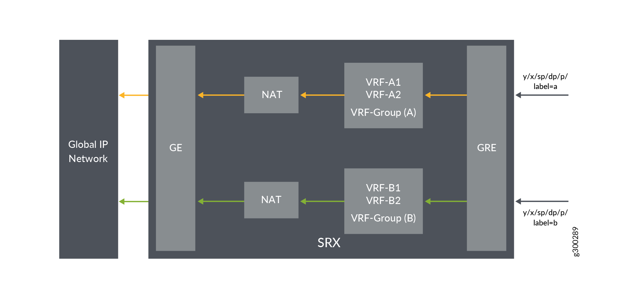
Source NAT is the translation of the source IP address of a packet leaving the Juniper Networks device. Source NAT is used to allow hosts with private IP addresses to access a public network.
In Figure 1, Firewall is configured with VRF group vpn-A and vpn-B, which are connected to the interfaces ge-0/0/1.0 and ge-0/0/1.1 on Firewall. In the hub Firewall, the source IP addresses 192.168.1.200 and 192.168.1.201 from VRF group vpn-A and vpn-B are translated to 203.0.113.200 and 203.0.113.201.
Configuration
Procedure
CLI Quick Configuration
To quickly configure this example, copy the
following commands, paste them into a text file, remove any line breaks,
change any details necessary to match your network configuration,
copy and paste the commands into the CLI at the [edit] hierarchy
level, and then enter commit from configuration mode.
set security l3vpn vrf-group vpn-A vrf VRF-A1
set security l3vpn vrf-group vpn-A vrf VRF-A2
set security l3vpn vrf-group vpn-B vrf VRF-B1
set security l3vpn vrf-group vpn-B vrf VRF-B2
set security nat source pool vrf-a_p address 203.0.113.200
set security nat source rule-set vrf-a_rs from routing-group vpn-A
set security nat source rule-set vrf-a_rs to interface ge-0/0/1.0
set security nat source rule-set vrf-a_rs rule rule1 match source-address 192.168.1.200
set security nat source rule-set vrf-a_rs rule rule1 then source-nat pool vrf-a_p
set security nat source pool vrf-b_p address 203.0.113.201
set security nat source rule-set vrf-b_rs from routing-group vpn-B
set security nat source rule-set vrf-b_rs to interface ge-0/0/1.1
set security nat source rule-set vrf-b_rs rule rule2 match source-address 192.168.1.201
set security nat source rule-set vrf-b_rs rule rule2 then source-nat pool vrf-b_p
Step-by-Step Procedure
The following example requires you to navigate various levels in the configuration hierarchy.
To configure source NAT mapping:
In Layer 3 VPNs create a VRF group vpn-A with VRF instances A1 and A2.
[edit security]
user@host#set l3vpn vrf-group vpn-A vrf VRF-A1
user@host#set l3vpn vrf-group vpn-A vrf VRF-A2
Create another VRF group vpn-B with VRF instances B1 and B2.
[edit security]
user@host#set l3vpn vrf-group vpn-B vrf VRF-B1
user@host#set l3vpn vrf-group vpn-B vrf VRF-B2
Create a source NAT pool.
[edit security nat source pool]
user@host#set vrf-a_p address 203.0.113.200
user@host#set vrf-b_p address 203.0.113.201
Create a source NAT rule set.
[edit security nat source]
user@host#set rule-set vrf-a_rs from routing-group vpn-A
user@host#set rule-set vrf-a_rs to interface ge-0/0/1.0
user@host#set rule-set vrf-b_rs from routing-group vpn-B
user@host#set rule-set vrf-b_rs to interface ge-0/0/1.1
Configure a rule that matches packets and translates the source IP address to an IP address in the source NAT pool.
[edit security nat source]
user@host# set rule-set vrf-a_rs rule rule1 match source-address 192.168.1.200
user@host# set rule-set vrf-a_rs rule rule1 then source-nat pool vrf-a_p
user@host# set rule-set vrf-b_rs rule rule2 match source-address 192.168.1.201
user@host# set rule-set vrf-b_rs rule rule2 then source-nat pool vrf-b_p
Results
From configuration mode, confirm your configuration
by entering the show security nat command. If the output
does not display the intended configuration, repeat the configuration
instructions in this example to correct it.
[edit]
user@host# show security nat
    source {
        pool vrf-a_p {
            address {
                203.0.113.200/32;
            }
        }
        pool vrf-b_p {
            address {
                203.0.113.201/32;
            }
        }
        rule-set vrf-a_rs {
            from routing-group vpn-A;
            to interface ge-0/0/1.0;
            rule rule1 {
                match {
                    source-address 192.168.1.200/32;
                }
                then {
                    source-nat {
                        pool {
                            vrf-a_p;
                        }
                    }
                }
            }
        }
        rule-set vrf-b_rs {
            from routing-group vpn-B;
            to interface ge-0/0/1.1;
            rule rule2 {
                match {
                    source-address 192.168.1.201/32;
                }
                then {
                    source-nat {
                        pool {
                            vrf-b_p;
                        }
                    }
                }
            }
        }
    }
If you are done configuring the device, enter commit from configuration mode.
Verification
Verifying Source NAT Rule Usage
Purpose
Verify that there is traffic matching the source NAT rule.
Action
From operational mode, enter the show security
nat source rule all command. In the Translation hits field,
verify whether there is traffic that matches the source NAT rule.
user@host>show security nat source rule all
Total rules: 2
Total referenced IPv4/IPv6 ip-prefixes: 2/0
rule: rule1                  Rule-set: vrf-a_rs
  Rule-Id                    : 1
  Rule position              : 1
  From routing-Group         : vpn-A
  To interface			         : ge-0/0/1.0
  Match
    Source addresses         : 192.168.1.200   - 192.168.1.200
  Action                        : vrf-a_p
    Persistent NAT type         : N/A
    Persistent NAT mapping type : address-port-mapping
    Inactivity timeout          : 0
    Max session number          : 0
  Translation hits           : 0
    Successful sessions      : 0
    Failed sessions          : 0
  Number of sessions         : 0
rule: rule2                  Rule-set: vrf-b_rs
  Rule-Id                    : 2
  Rule position              : 2
  From routing-Group         : vpn-B
  To interface			         : ge-0/0/1.1
  Match
    Source addresses         : 192.168.1.201   - 192.168.1.201
  Action                        : vrf-b_p
    Persistent NAT type         : N/A
    Persistent NAT mapping type : address-port-mapping
    Inactivity timeout          : 0
    Max session number          : 0
  Translation hits           : 0
    Successful sessions      : 0
    Failed sessions          : 0
  Number of sessions         : 0
Example: Configuring Destination NAT to Convert Public IP Address of a VRF Group to the private IP address of different VRF instance
This example describes how to configure the destination NAT mapping of a public IP address of a VRF group to the single VRF’s private address for directing the packets to the correct VRF instance.
Requirements
Understand how Firewalls work in an SD-WAN deployment for NAT.
Understand Virtual Routing and Forwarding Instances. See Virtual Routing and Forwarding Instances in SD-WAN Deployments.
Overview
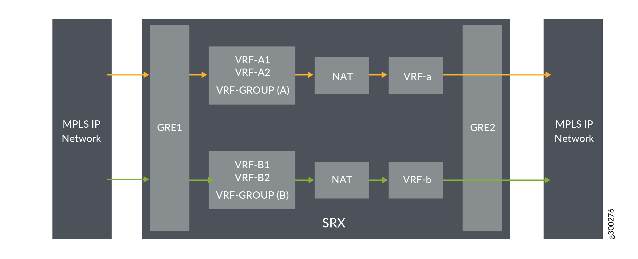
Destination NAT is the translation of the destination IP address of a packet entering the Juniper Networks device. Destination NAT is used to redirect traffic destined to a virtual host (identified by the original destination IP address) to the real host (identified by the translated destination IP address).
In Figure 2, the Firewall is configured destination NAT to convert from IP’s that belong to different VRF groups, to different set of IP’s with routing instance pointing to different VRF. After the destination NAT rule search, NAT updates the destination routing table to point to right VRF instance for flow to do destination route look-up in right table.
Configuration
Procedure
CLI Quick Configuration
To quickly configure this example, copy the
following commands, paste them into a text file, remove any line breaks,
change any details necessary to match your network configuration,
copy and paste the commands into the CLI at the [edit] hierarchy
level, and then enter commit from configuration mode.
set security l3vpn vrf-group vpn-A vrf VRF-A1
set security l3vpn vrf-group vpn-A vrf VRF-A2
set security l3vpn vrf-group vpn-B vrf VRF-B1
set security l3vpn vrf-group vpn-B vrf VRF-B2
set security nat destination pool vrf-a_p routing-instance VRF-a
set security nat destination pool vrf-a_p address 192.168.1.200
set security nat destination rule-set rs from routing-group vpn-A
set security nat destination rule-set rs rule vrf-a_r match destination-address 203.0.113.200
set security nat destination rule-set rs rule vrf-a_r then destination-nat pool vrf-a_p
set security nat destination pool vrf-b_p routing-instance VRF-b
set security nat destination pool vrf-b_p address 192.168.1.201
set security nat destination rule-set rs from routing-group vpn-B
set security nat destination rule-set rs rule vrf-b_r match destination-address 203.0.113.201
set security nat destination rule-set rs rule vrf-b_r then destination-nat pool vrf-b_p
Step-by-Step Procedure
The following example requires you to navigate various levels in the configuration hierarchy.
To configure destination NAT mapping for a single VRF:
In Layer 3 VPNs create a VRF group vpn-A with VRF instances A1 and A2.
[edit security]
user@host#set l3vpn vrf-group vpn-A vrf VRF-A1
user@host#set l3vpn vrf-group vpn-A vrf VRF-A2
Create another VRF group vpn-B with VRF instances B1 and B2.
[edit security]
user@host#set l3vpn vrf-group vpn-B vrf VRF-B1
user@host#set l3vpn vrf-group vpn-B vrf VRF-B2
Specify a destination NAT IP address pool.
[edit security nat destination]
user@host# set pool vrf-a_p address 192.168.1.200
user@host# set pool vrf-b_p address 192.168.1.201
Assign the routing instance to the destination pool.
[edit security nat destination]
user@host# set pool vrf-a_p routing-instance VRF-a
user@host# set pool vrf-b_p routing-instance VRF-b
Create a destination NAT rule set.
[edit security nat destination]
user@host# set rule-set rs from routing-group vpn-A
user@host# set rule-set rs from routing-group vpn-B
Configure a rule that matches packets and translates the destination IP address to an IP address in the destination NAT IP address pool.
[edit security nat destination]
user@host# set rule-set rs rule vrf-a_r match destination-address 203.0.113.200
user@host# set rule-set rs rule vrf-a_r then destination-nat pool vrf-a_p
user@host# set rule-set rs rule vrf-b_r match destination-address 203.0.113.201
user@host# set rule-set rs rule vrf-b_r then destination-nat pool vrf-b_p
Results
From configuration mode, confirm your configuration
by entering the show security nat command. If the output
does not display the intended configuration, repeat the configuration
instructions in this example to correct it.
[edit]
user@host# show security nat
    destination {
        pool vrf-a_p {
            routing-instance {
                VRF-a;
            }
            address 192.168.1.200/32;
        }
        pool vrf-b_p {
            routing-instance {
                VRF-b;
            }
            address 192.168.1.201/32;
        }
        rule-set rs {
            from routing-group [ vpn-A vpn-B ];
            rule vrf-a_r {
                match {
                    destination-address 203.0.113.200/32;
                }
                then {
                    destination-nat {
                        pool {
                            vrf-a_p;
                        }
                    }
                }
            }
            rule vrf-b_r {
                match {
                    destination-address 203.0.113.201/32;
                }
                then {
                    destination-nat {
                        pool {
                            vrf-b_p;
                        }
                    }
                }
            }
        }
    }
If you are done configuring the device, enter commit from configuration mode.
Verification
Verifying Destination NAT Rule Usage
Purpose
Verify that there is traffic matching the destination NAT rule.
Action
From operational mode, enter the show security
nat destination rule all command. In the Translation hits field,
verify whether there is traffic that matches the destination NAT rule.
user@host> show security nat destination rule all
Total destination-nat rules: 2
Total referenced IPv4/IPv6 ip-prefixes: 2/0
Destination NAT rule: vrf-a_r                Rule-set: rs
  Rule-Id                    : 1
  Rule position              : 1
  From routing-group         : vpn-A
  Destination addresses      : 203.0.113.200   - 203.0.113.200
  Action                     : vrf-a_p
  Translation hits           : 0
    Successful sessions      : 0
    Failed sessions          : 0
  Number of sessions         : 0
Destination NAT rule: vrf-b_r                Rule-set: rs
  Rule-Id                    : 2
  Rule position              : 2
  From routing-group         : vpn-A
  Destination addresses      : 203.0.113.201   - 203.0.113.201
  Action                     : vrf-b_p
  Translation hits           : 0
    Successful sessions      : 0
    Failed sessions          : 0
  Number of sessions         : 0