ON THIS PAGE
Security Policies Using VRF Group
Overview
In SD-WAN network, when different VRF based traffic enter the device from same tunnel such as GRE or GE, the device applies policy based on the given VRF instance. The device either permit or deny traffic destined to a particular VRF instance to control the VRF based traffic.
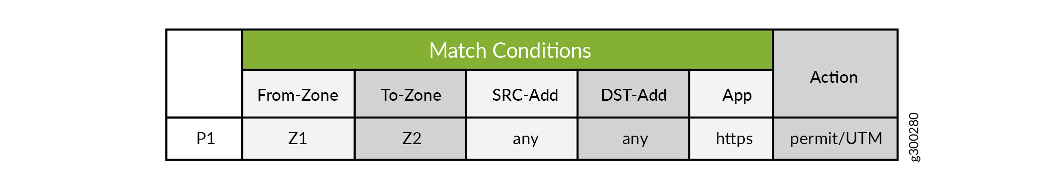
Currently, there are 5 matching conditions for each policy:
-
From zone
-
To zone
-
Source address
-
Destination address
-
Applications
Figure 1 shows the match conditions in a policy.
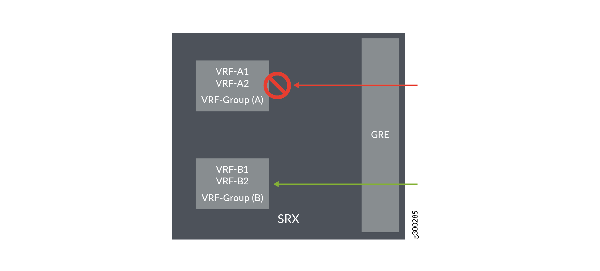
With the current policy matching conditions, you cannot permit VRF-B1 or VRF-B2 and deny VRF-A1 or VRF-A2. To support this, additional matching conditions are added to the policy in the SD-WAN network using VRF group.
When the flow receives the information of source and destination VRF groups, it forwards the information to policy search API along with the policy key tuple information to meet the match conditions.
Figure 2 shows the VRF groups added as match condition in a policy.
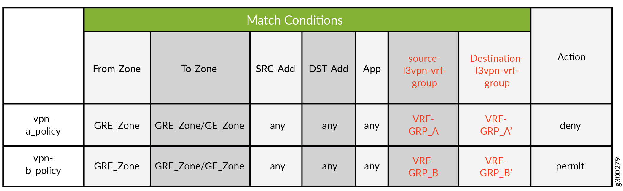
If the source and destination VRF group information is
not specified in a policy, then these groups matches any VRF group.
Example: Configuring a Security Policy to Permit VRF-Based Traffic from an IP Network to MPLS Network using VRF Group
This example shows how to configure a security policy to permit traffic from a private IP network to MPLs network using VRF group.
Requirements
-
Any supported Junos release.
-
On supported devices.
Overview
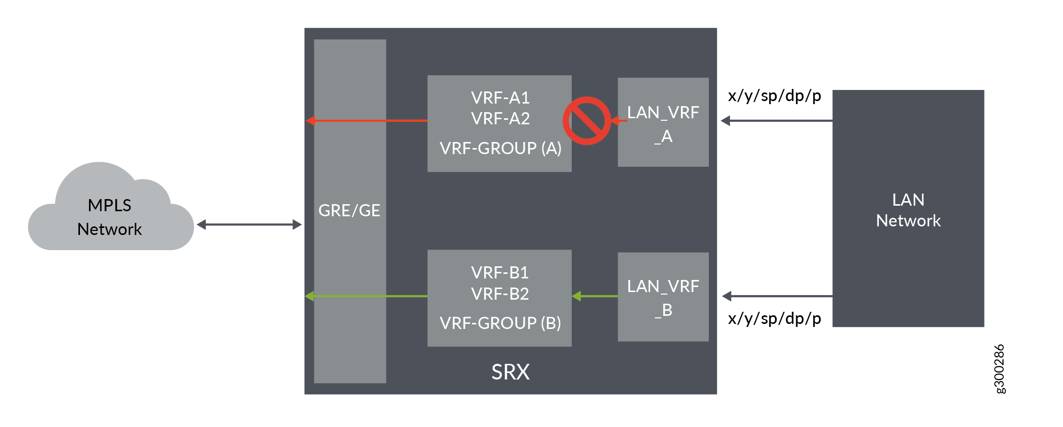
In Junos OS, security policies enforce rules for transit traffic, in terms of what traffic can pass through the device and the actions that need to take place on the traffic as it passes through the device. In Figure 3, an SRX Series Firewall is deployed in an SD-WAN to permit the traffic from a private IP network to MPLS network using VRF group.
This configuration example shows how to:
-
Permit traffic from IP network (LAN-a) to VRF group
-
Permit traffic from IP network (LAN-b) to VRF group
Configuration
Procedure
CLI Quick Configuration
To quickly configure this example, copy the following commands, paste them into
a text file, remove any line breaks, change any details necessary to match your
network configuration, copy and paste the commands into the CLI at the
[edit] hierarchy level, and then enter
commit from configuration mode.
set security l3vpn vrf-group vpn-A vrf VRF-A1
set security l3vpn vrf-group vpn-A vrf VRF-A2
set security l3vpn vrf-group vpn-A1 vrf VRF-A11
set security l3vpn vrf-group vpn-A1 vrf VRF-A21
set security l3vpn vrf-group vpn-B vrf VRF-B1
set security l3vpn vrf-group vpn-B vrf VRF-B2
set security l3vpn vrf-group vpn-B1 vrf VRF-B11
set security l3vpn vrf-group vpn-B1 vrf VRF-B21
set security policies from-zone LAN-a_Zone to-zone GRE_Zone policy vrf-a_policy match source-address any
set security policies from-zone LAN-a_Zone to-zone GRE_Zone policy vrf-a_policy match destination-address any
set security policies from-zone LAN-a_Zone to-zone GRE_Zone policy vrf-a_policy match application any
set security policies from-zone LAN-a_Zone to-zone GRE_Zone policy vrf-a_policy match destination-l3vpn-vrf-group vpn-A1
set security policies from-zone LAN-a_Zone to-zone GRE_Zone policy vrf-a_policy then permit
set security policies from-zone LAN-b_Zone to-zone GRE_Zone policy vrf-b_policy match source-address any
set security policies from-zone LAN-b_Zone to-zone GRE_Zone policy vrf-b_policy match destination-address any
set security policies from-zone LAN-b_Zone to-zone GRE_Zone policy vrf-b_policy match application any
set security policies from-zone LAN-b_Zone to-zone GRE_Zone policy vrf-b_policy match destination-l3vpn-vrf-group vpn-B1
set security policies from-zone LAN-b_Zone to-zone GRE_Zone policy vrf-b_policy then permit
Step-by-Step Procedure
The following example requires you to navigate various levels in the configuration hierarchy. For instructions on how to do that, see Using the CLI Editor in Configuration Mode in theCLI User Guide.
-
Create VRF group vpn-A with VRF instances A1 and A2
[edit security]
user@host# set l3vpn vrf-group vpn-A vrf VRF-A1
user@host# set l3vpn vrf-group vpn-A vrf VRF-A2
-
Create VRF group vpn-A1 with VRF instances A11, and A21
[edit security]
user@host# set l3vpn vrf-group vpn-A1 vrf VRF-A11
user@host# set l3vpn vrf-group vpn-A1 vrf VRF-A21
-
Create VRF group vpn-B with VRF instances B1 and B2
[edit security]
user@host# set l3vpn VRF group vpn-B vrf VRF-B1
user@host# set l3vpn VRF group vpn-B vrf VRF-B2
-
Create VRF group vpn-B1 with VRF instances B11 and B21
[edit security]
user@host# set l3vpn vrf-group vpn-B1 vrf VRF-B11
user@host# set l3vpn vrf-group vpn-B1 vrf VRF-B21
-
Create a security policy to permit vrf-a traffic.
[edit security policies from-zone LAN-a_Zone to-zone GRE_Zone]
user@host# set policy vrf-a_policy match source-address any
user@host# set policy vrf-a_policy match destination-address any
user@host# set policy vrf-a_policy match application any
user@host# set policy vrf-a_policy match destination-l3vpn-vrf-group vpn-A1
user@host# set policy vrf-a_policy then permit
-
Create a security policy to permit vrf-b traffic.
[edit security policies from-zone LAN-a_Zone to-zone GRE_Zone]
user@host# set policy vrf-b_policy match source-address any
user@host# set policy vrf-b_policy match destination-address any
user@host# set policy vrf-b_policy match application any
user@host# set policy vrf-b_policy match destination-l3vpn-vrf-group vpn-B1
user@host# set policy vrf-b_policy then permit
Results
From configuration mode, confirm your configuration by entering the
show security policies command. If the output does not
display the intended configuration, repeat the configuration instructions in
this example to correct it.
[edit]
user@host# show security policies
from-zone LAN-a_Zone to-zone GRE_Zone {
    policy vrf-a_policy {
        match {
            source-address any;
            destination-address any;
            application any;
            source-l3vpn-VRF group vpn-A1;
        }
        then {
            permit;
        }
    }
from-zone LAN-b_Zone to-zone GRE_Zone {
    policy vrf-b_policy {
        match {
            source-address any;
            destination-address any;
            application any;
            source-l3vpn-VRF group vpn-B1;
        }
        then {
            permit;
        }
        }
    }
If you are done configuring the device, enter commit from
configuration mode.
Verification
Verifying Policy Configuration
Purpose
Verify information about security policies.
Action
From operational mode, enter the show security policies
command to display a summary of all the security policies configured on the
device.
user@root> show security policies
Default policy: permit-all
From zone: LAN-a_Zone, To zone: GRE_Zone
  Policy: vrf-a_policy, State: enabled, Index: 4, Scope Policy: 0, Sequence number: 1
    Source L3VPN vrf-group: vpn-A1
    destination L3VPN VRF Group: any
    Source addresses: any
    Destination addresses: any
    Applications: any
    Action: permit
From zone: LAN-b_Zone, To zone: GRE_Zone
  Policy: vrf-b_policy, State: enabled, Index: 5, Scope Policy: 0, Sequence number: 2
    Source L3VPN vrf-group: vpn-B1
    destination L3VPN VRF Group: any
    Source addresses: any
    Destination addresses: any
    Applications: any
    Action: permit
Example: Configuring a Security Policy to Permit VRF-Based Traffic from MPLS Network to an IP Network using VRF Group
This example shows how to configure a security policy to permit traffic from MPLS to IP netwrok using the VRF group.
Requirements
-
-
Any supported Junos release.
-
On supported devices.
-
-
Configure network interfaces on the device. See Interfaces User Guide for Security Devices.
Overview
In Junos OS, security policies enforce rules for transit traffic, in terms of what traffic can pass through the device and the actions that need to take place on the traffic as it passes through the device. In Figure 4, the firewall is deployed in an SD-WAN to permit traffic from a MPLS network to private network using VRF group.
This configuration example shows how to:
-
Permit traffic from GRE MPLS to LAN-a
-
Permit traffic from GRE MPLS to LAN-b
Configuration
Procedure
CLI Quick Configuration
To quickly configure this example, copy the following commands, paste them into
a text file, remove any line breaks, change any details necessary to match your
network configuration, copy and paste the commands into the CLI at the
[edit] hierarchy level, and then enter
commit from configuration mode.
set security l3vpn vrf-group vpn-A vrf VRF-A1
set security l3vpn vrf-group vpn-A vrf VRF-A2
set security l3vpn vrf-group vpn-B vrf VRF-B1
set security l3vpn vrf-group vpn-B vrf VRF-B2
set security policies from-zone GRE_Zone to-zone LAN-a_Zone  policy vrf-a_policy match source-address any
set security policies from-zone GRE_Zone to-zone LAN-a_Zone  policy vrf-a_policy match destination-address any
set security policies from-zone GRE_Zone to-zone LAN-a_Zone  policy vrf-a_policy match application any
set security policies from-zone GRE_Zone to-zone LAN-a_Zone  policy vrf-a_policy match source-l3vpn-vrf-group vpn-A
set security policies from-zone GRE_Zone to-zone LAN-a_Zone  policy vrf-a_policy then permit
set security policies from-zone GRE_Zone to-zone LAN-b_Zone  policy vrf-b_policy match source-address any
set security policies from-zone GRE_Zone to-zone LAN-b_Zone  policy vrf-b_policy match destination-address any
set security policies from-zone GRE_Zone to-zone LAN-b_Zone  policy vrf-b_policy match application any
set security policies from-zone GRE_Zone to-zone LAN-b_Zone  policy vrf-b_policy match source-l3vpn-vrf-group vpn-B
set security policies from-zone GRE_Zone to-zone LAN-b_Zone  policy vrf-b_policy then permit
Step-by-Step Procedure
The following example requires you to navigate various levels in the configuration hierarchy. For instructions on how to do that, see Using the CLI Editor in Configuration Mode in theCLI User Guide.
-
Create VRF group vpn-A with VRF instances A1 and A2.
[edit security]
user@host# set l3vpn vrf-group vpn-A vrf VRF-A1
user@host# set l3vpn vrf-group vpn-A vrf VRF-A2
-
Create VRF group vpn-B with VRF instances B1 and B2.
[edit security]
user@host# set l3vpn vrf-group vpn-B vrf VRF-B1
user@host# set l3vpn vrf-group vpn-B vrf VRF-B2
-
Create a security policy to permit VRF-a traffic.
[edit security policies from-zone GRE_Zone to-zone LAN-a_Zone]
user@host# set policy vrf-a_policy match source-address any
user@host# set policy vrf-a_policy match destination-address any
user@host# set policy vrf-a_policy match application any
user@host# set policy vrf-a_policy match source-l3vpn-vrf-group vpn-A
user@host# set policy vrf-a_policy then permit
-
Create a security policy to permit VRF-b traffic.
[edit security policies from-zone GRE_Zone to-zone LAN-b_Zone]
user@host# set policy vrf-b_policy match source-address any
user@host# set policy vrf-b_policy match destination-address any
user@host# set policy vrf-b_policy match application any
user@host# set policy vrf-b_policy match destination-l3vpn-vrf-group vpn-B
user@host# set policy vrf-b_policy then permit
Results
From configuration mode, confirm your configuration by entering the
show security policies command. If the output does not
display the intended configuration, repeat the configuration instructions in
this example to correct it.
[edit]
user@host# show security policies
from-zone GRE_Zone to-zone LAN-a_Zone {
    policy vrf-a_policy {
        match {
            source-address any;
            destination-address any;
            application any;
            destination-l3vpn-vrf-group vpn-A;
        }
        then {
            permit;
        }
    }
from-zone GRE_Zone to-zone LAN-b_Zone {
    policy vrf-b_policy {
        match {
            source-address any;
            destination-address any;
            application any;
            destination-l3vpn-vrf-group vpn-B;
        }
        then {
            permit;
        }
    }
}
If you are done configuring the device, enter commit from
configuration mode.
Verification
Verifying Policy Configuration
Purpose
Verify information about security policies.
Action
From operational mode, enter the show security policies
command to display a summary of all the security policies configured on the
device.
user@root> show security policies
Default policy: permit-all
From zone: GRE_Zone, To zone: LAN-a_Zone
  Policy: vrf-a_policy, State: enabled, Index: 4, Scope Policy: 0, Sequence number: 1
    Source L3VPN VRF-Group: any
    destination L3VPN VRF Group: vpn-A
    Source addresses: any
    Destination addresses: any
    Applications: any
    Action: permit
From zone: GRE_Zone, To zone: LAN-b_Zone
  Policy: vrf-b_policy, State: enabled, Index: 5, Scope Policy: 0, Sequence number: 2
    Source L3VPN VRF Group: any
    destination L3VPN VRF-Group: vpn-B
    Source addresses: any
    Destination addresses: any
    Applications: any
    Action: permit
Example: Configuring a Security Policy to Permit VRF-Based Traffic from Public IP Network to MPLS Network using VRF Group
This example describes how to configure the destination NAT rule to translate incoming public IP network to MPLS network using VRF group.
Requirements
-
Understand how SRX Series Firewalls work in an SD-WAN deployment for NAT.
-
Understand Virtual Routing and Forwarding Instances. See Virtual Routing and Forwarding Instances in SD-WAN Deployments.
Overview
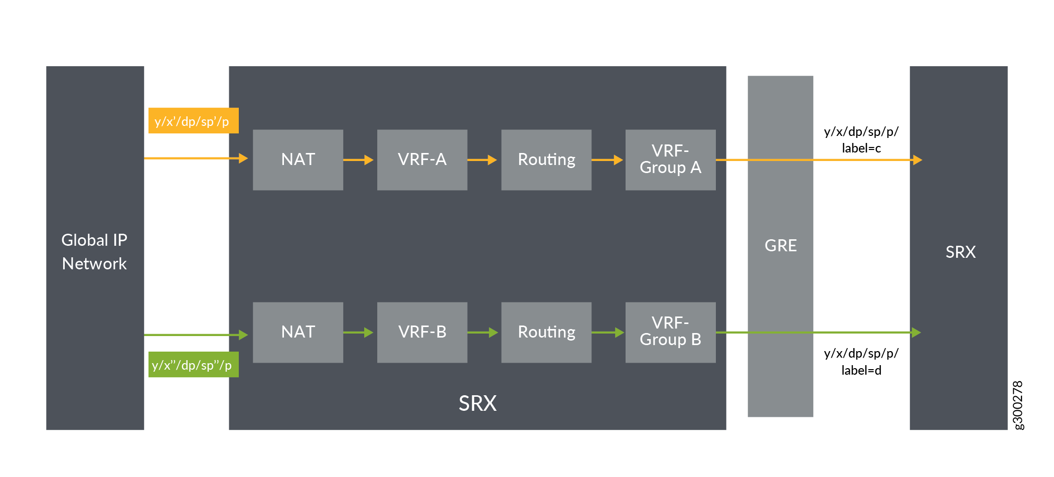
In Figure 5, the firewall is configured with destination NAT rule to translate incoming public IP network to per VRF based destination routing table and IP. The firewall is configured with two VRF groups, vpn-A and vpn-B.
Configuration
Procedure
CLI Quick Configuration
To quickly configure this example, copy the following commands, paste them into
a text file, remove any line breaks, change any details necessary to match your
network configuration, copy and paste the commands into the CLI at the
[edit] hierarchy level, and then enter
commit from configuration mode.
set security l3vpn vrf-group vpn-A vrf VRF-A1
set security l3vpn vrf-group vpn-A vrf VRF-A2
set security l3vpn vrf-group vpn-B vrf VRF-B1
set security l3vpn vrf-group vpn-B vrf VRF-B2
set security nat destination pool vrf-a_p routing-instance VRF-a
set security nat destination pool vrf-a_p address 192.168.1.200
set security nat destination rule-set rs from interface ge-0/0/1.0
set security nat destination rule-set rs rule vrf-a_r match destination-address 203.0.113.200
set security nat destination rule-set rs rule vrf-a_r then destination-nat pool vrf-a_p
set security nat destination pool vrf-b_p routing-instance VRF-b
set security nat destination pool vrf-b_p address 192.168.1.201
set security nat destination rule-set rs from interface ge-0/0/1.1
set security nat destination rule-set rs rule vrf-b_r match destination-address 203.0.113.201
set security nat destination rule-set rs rule vrf-b_r then destination-nat pool vrf-b_p
set security policies from-zone GE_Zone to-zone GRE_Zone policy vrf-a_policy match source-address any
set security policies from-zone GE_Zone to-zone GRE_Zone policy vrf-a_policy match destination-address any
set security policies from-zone GE_Zone to-zone GRE_Zone policy vrf-a_policy match application any
set security policies from-zone GE_Zone to-zone GRE_Zone policy vrf-a_policy match source-l3vpn-vrf-group vpn-A
set security policies from-zone GE_Zone to-zone GRE_Zone policy vrf-a_policy then permit
set security policies from-zone GE_Zone to-zone GRE_Zone policy vrf-b_policy match source-address any
set security policies from-zone GE_Zone to-zone GRE_Zone policy vrf-b_policy match destination-address any
set security policies from-zone GE_Zone to-zone GRE_Zone policy vrf-b_policy match application any
set security policies from-zone GE_Zone to-zone GRE_Zone policy vrf-b_policy match source-l3vpn-vrf-group vpn-B
set security policies from-zone GE_Zone to-zone GRE_Zone policy vrf-b_policy then permit
Step-by-Step Procedure
The following example requires you to navigate various levels in the configuration hierarchy. For instructions on how to do that, see Using the CLI Editor in Configuration Mode in theCLI User Guide.
To configure destination NAT mapping for a single VRF:
-
In Layer 3 VPNs create a VRF group vpn-A with VRF instances A1 and A2.
[edit security]
user@host#set l3vpn vrf-group vpn-A vrf VRF-A1
user@host#set l3vpn vrf-group vpn-A vrf VRF-A2
-
Create another VRF group vpn-B with VRF instances B1 and B2.
[edit security]
user@host#set l3vpn vrf-group vpn-B vrf VRF-B1
user@host#set l3vpn vrf-group vpn-B vrf VRF-B2
-
Specify a destination NAT IP address pool.
[edit security nat destination] user@host# set pool vrf-a_p address 192.168.1.200 user@host# set pool vrf-b_p address 192.168.1.201 -
Assign the routing instance to the destination pool.
[edit security nat destination]
user@host# set pool vrf-a_p routing-instance VRF-a
user@host# set pool vrf-b_p routing-instance VRF-b
-
Create a destination NAT rule set.
[edit security nat destination]
user@host# set rule-set rs from routing-group vpn-A
user@host# set rule-set rs from routing-group vpn-B
user@host# set rule-set rs from interface ge-0/0/1.0
user@host# set rule-set rs from interface ge-0/0/1.1
-
Configure a rule that matches packets and translates the destination IP address to an IP address in the destination NAT IP address pool.
[edit security nat destination]
user@host# set rule-set rs rule vrf-a_r match destination-address 203.0.113.200
user@host# set rule-set rs rule vrf-a_r then destination-nat pool vrf-a_p
user@host# set rule-set rs rule vrf-b_r match destination-address 203.0.113.201
user@host# set rule-set rs rule vrf-b_r then destination-nat pool vrf-b_p
-
Create a security policy to permit VRF-a traffic.
[edit security policies from-zone GE_Zone to-zone GRE_Zone]
user@host# set policy vrf-a_policy match source-address any
user@host# set policy vrf-a_policy match destination-address any
user@host# set policy vrf-a_policy match application any
user@host# set policy vrf-a_policy match destination-l3vpn-vrf-group vpn-A
user@host# set policy vrf-a_policy then permit
-
Create a security policy to permit VRF-b traffic.
[edit security policies from-zone GE_Zone to-zone GRE_Zone]
user@host# set policy vrf-b_policy match source-address any
user@host# set policy vrf-b_policy match destination-address any
user@host# set policy vrf-b_policy match application any
user@host# set policy vrf-b_policy match destination-l3vpn-vrf-group vpn-B
user@host# set policy vrf-b_policy then permit
Results
From configuration mode, confirm your configuration by entering the show
security nat and show security policies commands. If
the output does not display the intended configuration, repeat the configuration
instructions in this example to correct it.
[edit]
user@host# show security nat
    destination {
        pool vrf-a_p {
            routing-instance {
                VRF-a;
            }
            address 192.168.1.200/32;
        }
        pool vrf-b_p {
            routing-instance {
                VRF-b;
            }
            address 192.168.1.201/32;
        }
        rule-set rs {
            from interface [  ge-0/0/1.0 ge-0/0/1.1 ];
            rule vrf-a_r {
                match {
                    destination-address 203.0.113.200/32;
                }
                then {
                    destination-nat {
                        pool {
                            vrf-a_p;
                        }
                    }
                }
            }
            rule vrf-b_r {
                match {
                    destination-address 203.0.113.201/32;
                }
                then {
                    destination-nat {
                        pool {
                            vrf-b_p;
                        }
                    }
                }
            }
        }
    }
[edit]
user@host# show security policies
from-zone GE_Zone to-zone GRE_Zone {
    policy vrf-a_policy {
        match {
            source-address any;
            destination-address any;
            application any;
            destination-l3vpn-vrf-group vpn-A;
        }
        then {
            permit;
        }
    }
    policy vrf-b_policy {
        match {
            source-address any;
            destination-address any;
            application any;
            destination-l3vpn-vrf-group vpn-B;
        }
        then {
            permit;
        }
    }
If you are done configuring the device, enter commit from
configuration mode.
Verification
Verifying Destination NAT Rule Usage and Security Policies
Purpose
Verify that there is traffic matching the destination NAT rule.
Action
From operational mode, enter the show security nat destination rule
all command. In the Translation hits field, verify whether there is
traffic that matches the destination NAT rule.
user@host> show security nat destination rule all
Total destination-nat rules: 2
Total referenced IPv4/IPv6 ip-prefixes: 2/0
Destination NAT rule: vrf-a_r                Rule-set: rs
  Rule-Id                    : 1
  Rule position              : 1
  From interface         		 : ge-0/0/1.0
  Destination addresses      : 203.0.113.200   - 203.0.113.200
  Action                     : vrf-a_p
  Translation hits           : 0
    Successful sessions      : 0
    Failed sessions          : 0
  Number of sessions         : 0
    Destination NAT rule		 : vrf-b_r
  Rule-set									 : rs
  Rule-Id                    : 2
  Rule position              : 2
  From interface             : ge-0/0/1.1
  Destination addresses      : 203.0.113.201   - 203.0.113.201
  Action                     : vrf-b_p
  Translation hits           : 0
    Successful sessions      : 0
    Failed sessions          : 0
  Number of sessions         : 0
From operational mode, enter the show security policies
command to display a summary of all the security policies configured on the
device.
user@root> show security policies
Default policy: permit-all
From zone: GE_Zone, To zone: GRE_Zone
  Policy: vrf-a_policy, State: enabled, Index: 4, Scope Policy: 0, Sequence number: 1
    Source L3VPN VRF Group: any
    destination L3VPN VRF-Group: vpn-A
    Source addresses: any
    Destination addresses: any
    Applications: any
    Action: permit
From zone: GE_Zone, To zone: GRE_Zone
  Policy: vrf-b_policy, State: enabled, Index: 5, Scope Policy: 0, Sequence number: 2
    Source L3VPN VRF Group: any
    destination L3VPN VRF-Group: vpn-B
    Source addresses: any
    Destination addresses: any
    Applications: any
    Action: permit
Example: Configuring a Security Policy to Permit VRF-Based Traffic from MPLS Network to Public IP Network to using VRF Group
This example describes how to configure the routing group to translate per VRF group network traffic to global IP pool.
Requirements
-
Understand how the firewall work in an SD-WAN deployment for NAT.
-
Understand Virtual Routing and Forwarding Instances. See Virtual Routing and Forwarding Instances in SD-WAN Deployments.
Overview
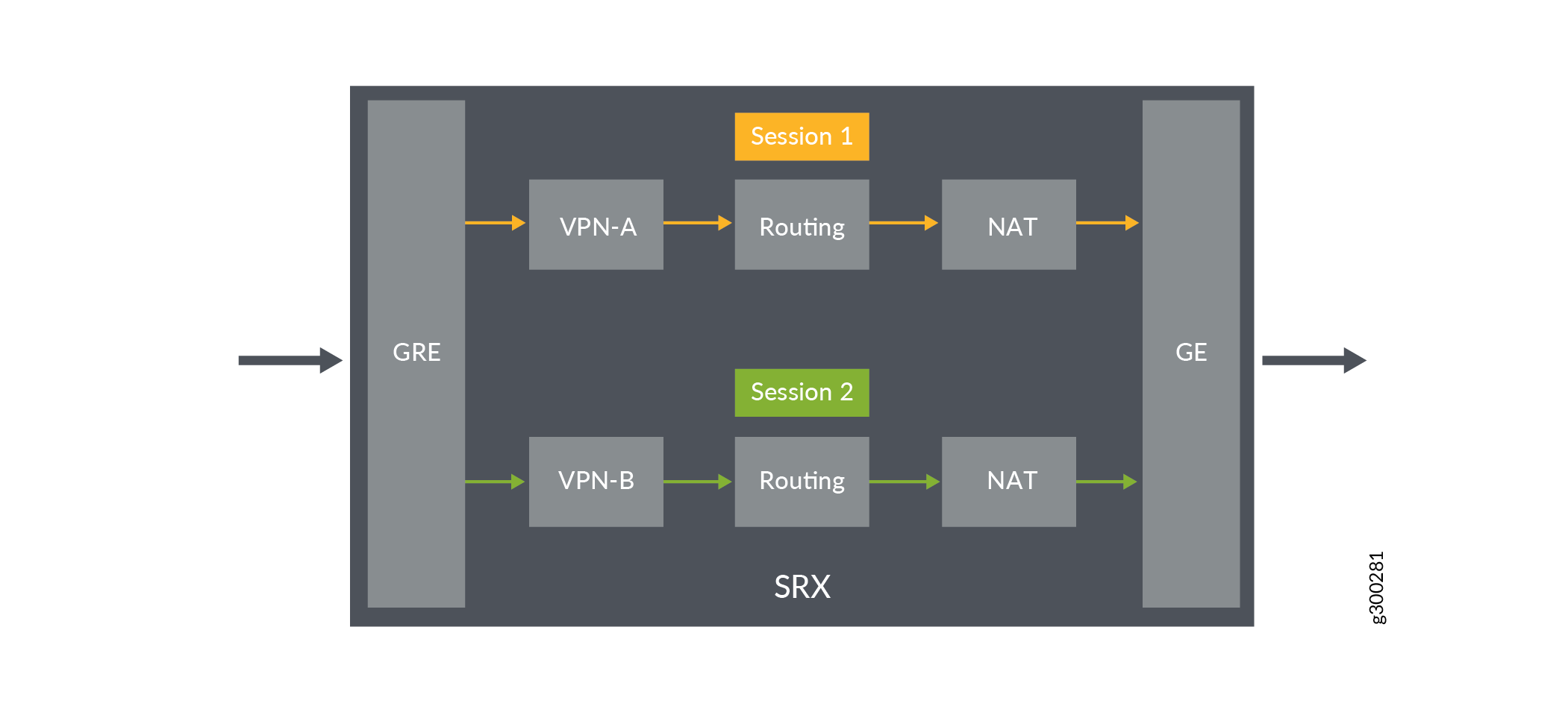
In Figure 6, the firewall is configured with routing group to permit VRF group network traffic from MPLS to global IP pool. The firewall is configured with two VRF groups, vpn-A and vpn-B.
Configuration
Procedure
CLI Quick Configuration
To quickly configure this example, copy the following commands, paste them into
a text file, remove any line breaks, change any details necessary to match your
network configuration, copy and paste the commands into the CLI at the
[edit] hierarchy level, and then enter
commit from configuration mode.
set security l3vpn vrf-group vpn-A vrf VRF-A1
set security l3vpn vrf-group vpn-A vrf VRF-A2
set security l3vpn vrf-group vpn-B vrf VRF-B1
set security l3vpn vrf-group vpn-B vrf VRF-B2
set security nat source pool vrf-a_p address 203.0.113.200
set security nat source rule-set vrf-a_rs from routing-group vpn-A
set security nat source rule-set vrf-a_rs to zone GE_Zone
set security nat source rule-set vrf-a_rs rule rule1 match source-address 192.168.1.200
set security nat source rule-set vrf-a_rs rule rule1 then source-nat pool vrf-a_p
set security nat source pool vrf-b_p address 203.0.113.201
set security nat source rule-set vrf-b_rs from routing-group vpn-B
set security nat source rule-set vrf-b_rs to zone GE_Zone
set security nat source rule-set vrf-b_rs rule rule2 match source-address 192.168.1.201
set security nat source rule-set vpn-b_rs rule rule2 then source-nat pool vrf-b_p
set security policies from-zone GRE_Zone to-zone GE_Zone policy vrf-a_policy match source-address any
set security policies from-zone GRE_Zone to-zone GE_Zone policy vrf-a_policy match destination-address any
set security policies from-zone GRE_Zone to-zone GE_Zone policy vrf-a_policy match application any
set security policies from-zone GRE_Zone to-zone GE_Zone policy vrf-a_policy match source-l3vpn-vrf-group vpn-A
set security policies from-zone GRE_Zone to-zone GE_Zone policy vrf-a_policy then permit
set security policies from-zone GRE_Zone to-zone GE_Zone policy vrf-b_policy match source-address any
set security policies from-zone GRE_Zone to-zone GE_Zone policy vrf-b_policy match destination-address any
set security policies from-zone GRE_Zone to-zone GE_Zone policy vrf-b_policy match application any
set security policies from-zone GRE_Zone to-zone GE_Zone policy vrf-b_policy match source-l3vpn-vrf-group vpn-B
set security policies from-zone GRE_Zone to-zone GE_Zone policy vrf-b_policy then permit
Step-by-Step Procedure
The following example requires you to navigate various levels in the configuration hierarchy. For instructions on how to do that, see Using the CLI Editor in Configuration Mode in theCLI User Guide.
To configure source NAT mapping for a single VRF:
-
In Layer 3 VPNs create a VRF group vpn-A with VRF instances A1 and A2.
[edit security]
user@host#set l3vpn vrf-group vpn-A vrf VRF-A1
user@host#set l3vpn vrf-group vpn-A vrf VRF-A2
-
Create another VRF group vpn-B with VRF instances B1 and B2.
[edit security]
user@host#set l3vpn vrf-group vpn-B vrf VRF-B1
user@host#set l3vpn vrf-group vpn-B vrf VRF-B2
-
Specify a source NAT IP address pool.
[edit security nat source] user@host# set pool vrf-a_p address 192.168.1.200 user@host# set pool vrf-b_p address 192.168.1.201 -
Create a source NAT rule set.
[edit security nat source]
user@host# set rule-set rs from routing-group vpn-A
user@host# set rule-set rs from routing-group vpn-B
user@host# set rule-set rs to zone GE_Zone
-
Configure a rule that matches packets and translates per VRF group network traffic to global IP pool.
[edit security nat source]
user@host# set rule-set rs rule vrf-a_r match destination-address 203.0.113.200
user@host# set rule-set rs rule vrf-a_r then destination-nat pool vrf-a_p
user@host# set rule-set rs rule vrf-b_r match destination-address 203.0.113.201
user@host# set rule-set rs rule vrf-b_r then destination-nat pool vrf-b_p
-
Create a security policy to permit vpn-A traffic.
[edit security policies from-zone GRE_Zone to-zone GE_Zone]
user@host# set policy vrf-a_policy match source-address any
user@host# set policy vrf-a_policy match destination-address any
user@host# set policy vrf-a_policy match application any
user@host# set policy vrf-a_policy match destination-l3vpn-vrf-group vpn-A
user@host# set policy vrf-a_policy then permit
-
Create a security policy to permit vpn-B traffic.
[edit security policies from-zone GRE_Zone to-zone GE_Zone]
user@host# set policy vrf-b_policy match source-address any
user@host# set policy vrf-b_policy match destination-address any
user@host# set policy vrf-b_policy match application any
user@host# set policy vrf-b_policy match destination-l3vpn-vrf-group vpn-B
user@host# set policy vrf-b_policy then permit
Results
From configuration mode, confirm your configuration by entering the show
security nat and show security policies commands. If
the output does not display the intended configuration, repeat the configuration
instructions in this example to correct it.
[edit]
user@host# show security nat
    source {
        pool vrf-a_p {
            address {
                203.0.113.200/32;
            }
        }
        pool vrf-b_p {
            address {
                203.0.113.201/32;
            }
        }
        rule-set vrf-a_rs {
            from routing-group vpn-A;
            to zone GE_Zone1;
            rule rule1 {
                match {
                    source-address 192.168.1.200/32;
                }
                then {
                    source-nat {
                        pool {
                            vrf-a_p;
                        }
                    }
                }
            }
            rule-set vrf-b_rs {
                from routing-group vpn-B;
                to zone GE_Zone;
                match {
                    source-address 192.168.1.201/32;
                }
                then {
                    source-nat {
                        pool {
                            vrf-b_p;
                        }
                    }
                }
            }
        }
    }
[edit]
user@host# show security policies
from-zone GRE_Zone to-zone GE_Zone {
    policy vrf-a_policy {
        match {
            source-address any;
            destination-address any;
            application any;
            destination-l3vpn-vrf-group vpn-A;
        }
        then {
            permit;
        }
    }
    policy vrf-b_policy {
        match {
            source-address any;
            destination-address any;
            application any;
            destination-l3vpn-vrf-group vpn-B;
        }
        then {
            permit;
        }
    }
}
If you are done configuring the device, enter commit from
configuration mode.
Verification
Verifying Destination NAT Rule Usage and Security Policies
Purpose
Verify that there is traffic matching the source NAT rule.
Action
From operational mode, enter the show security nat source rule
all command. In the Translation hits field, verify whether there is
traffic that matches the source NAT rule.
user@host> show security nat source rule all
Total source-nat rules: 2
Total referenced IPv4/IPv6 ip-prefixes: 2/0
Source NAT rule						: vrf-a_r
Rule-set: rs
  Rule-Id                    : 1
  Rule position              : 1
  From routing-group         : vpn-A  To zone                    : GE_Zone1
  Source addresses      		 : 203.0.113.200   - 203.0.113.200
  Action                     : vrf-a_p
  Translation hits           : 0
    Successful sessions      : 0
    Failed sessions          : 0
  Number of sessions         : 0
Source NAT rule						 : vrf-b_r
Rule-set: rs
  Rule-Id                    : 2
  Rule position              : 2
  From routing-group         : vpn-A
  To zone                    : GE_Zone
  Destination addresses      : 203.0.113.201   - 203.0.113.201
  Action                     : vrf-b_p
  Translation hits           : 0
    Successful sessions      : 0
    Failed sessions          : 0
  Number of sessions         : 0
From operational mode, enter the show security policies
command to display a summary of all the security policies configured on the
device.
user@root> show security policies
Default policy: permit-all
From zone: GRE_Zone, To zone: GE_Zone
  Policy: vrf-a_policy, State: enabled, Index: 4, Scope Policy: 0, Sequence number: 1
    Source L3VPN VRF Group: any
    destination L3VPN VRF Group: vpn-A
    Source addresses: any
    Destination addresses: any
    Applications: any
    Action: permit
From zone: GRE_Zone, To zone: GE_Zone
  Policy: vrf-b_policy, State: enabled, Index: 5, Scope Policy: 0, Sequence number: 2
    Source L3VPN VRF Group: any
    destination L3VPN VRF Group: vpn-B
    Source addresses: any
    Destination addresses: any
    Applications: any
    Action: permit
Example: Configuring a Security Policy to Permit VRF-Based Traffic from MPLS Network to MPLS Network without NAT using VRF Group
This example describes how to configure the routing group to permit traffic between MPLS networks without using NAT.
Requirements
-
Understand how the firewall work in an SD-WAN deployment for NAT.
-
Understand Virtual Routing and Forwarding Instances. See Virtual Routing and Forwarding Instances in SD-WAN Deployments.
Overview
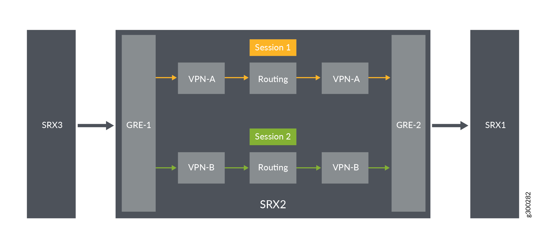
In Figure 7, the firewall is configured with routing group to permit traffic between MPLS networks without using NAT. The firewall is configured with two VRF groups, vpn-A and vpn-B.
Configuration
Procedure
CLI Quick Configuration
To quickly configure this example, copy the following commands, paste them into
a text file, remove any line breaks, change any details necessary to match your
network configuration, copy and paste the commands into the CLI at the
[edit] hierarchy level, and then enter
commit from configuration mode.
set security l3vpn vrf-group vpn-A vrf VRF-A1
set security l3vpn vrf-group vpn-A vrf VRF-A2
set security l3vpn vrf-group vpn-A1 vrf VRF-A11
set security l3vpn vrf-group vpn-A1 vrf VRF-A12
set security l3vpn vrf-group vpn-B vrf VRF-B1
set security l3vpn vrf-group vpn-B vrf VRF-B2
set security l3vpn vrf-group vpn-B1 vrf VRF-B11
set security l3vpn vrf-group vpn-B1 vrf VRF-B12
set security policies from-zone GRE-1_Zone to-zone GRE-2_Zone policy vrf-a_policy match source-address any
set security policies from-zone GRE-1_Zone to-zone GRE-2_Zone policy vrf-a_policy match destination-address any
set security policies from-zone GRE-1_Zone to-zone GRE-2_Zone policy vrf-a_policy match application any
set security policies from-zone GRE-1_Zone to-zone GRE-2_Zone policy vrf-a_policy match source-l3vpn-vrf-group vpn-A1
set security policies from-zone GRE-1_Zone to-zone GRE-2_Zone policy vrf-a_policy then permit
set security policies from-zone GRE-1_Zone to-zone GRE-2_Zone policy vrf-b_policy match source-address any
set security policies from-zone GRE-1_Zone to-zone GRE-2_Zone policy vrf-b_policy match destination-address any
set security policies from-zone GRE-1_Zone to-zone GRE-2_Zone policy vrf-b_policy match application any
set security policies from-zone GRE-1_Zone to-zone GRE-2_Zone policy vrf-b_policy match source-l3vpn-vrf-group vpn-B1
set security policies from-zone GRE-1_Zone to-zone GRE-2_Zone policy vrf-b_policy then permit
Step-by-Step Procedure
The following example requires you to navigate various levels in the configuration hierarchy. For information about navigating the CLI, see Using the CLI Editor in Configuration Mode in the CLI User Guide.
To configure source NAT mapping for a single VRF:
-
In Layer 3 VPNs create a VRF group vpn-A with VRF instances A1and A2.
[edit security]
user@host#set l3vpn vrf-group vpn-A vrf VRF-A1
user@host#set l3vpn vrf-group vpn-A vrf VRF-A2
-
In Layer 3 VPNs create a VRF group vpn-A1 with VRF instances A11and A12.
[edit security]
user@host#set l3vpn vrf-group vpn-A1 vrf VRF-A11
user@host#set l3vpn vrf-group vpn-A1 vrf VRF-A12
-
Create another VRF group vpn-B with VRF instances B1 and B2.
[edit security]
user@host#set l3vpn vrf-group vpn-B vrf VRF-B1
user@host#set l3vpn vrf-group vpn-B vrf VRF-B2
-
Create another VRF group vpn-B1 with VRF instances B11 and B12.
[edit security]
user@host#set l3vpn vrf-group vpn-B1 vrf VRF-B11
user@host#set l3vpn vrf-group vpn-B1 vrf VRF-B12
-
Create a security policy to permit vpn-A1 traffic.
[edit security policies from-zone GRE-1_Zone to-zone GRE-2_Zone]
user@host# set policy vrf-a_policy match source-address any
user@host# set policy vrf-a_policy match destination-address any
user@host# set policy vrf-a_policy match application any
user@host# set policy vrf-a_policy match destination-l3vpn-vrf-group vpn-A1
user@host# set policy vrf-a_policy then permit
-
Create a security policy to permit vpn-B1 traffic.
[edit security policies from-zone GRE-1_Zone to-zone GRE-2_Zone]
user@host# set policy vrf-b_policy match source-address any
user@host# set policy vrf-b_policy match destination-address any
user@host# set policy vrf-b_policy match application any
user@host# set policy vrf-b_policy match destination-l3vpn-vrf-group vpn-B1
user@host# set policy vrf-b_policy then permit
Results
From configuration mode, confirm your configuration by entering the show
security policies command. If the output does not display the intended
configuration, repeat the configuration instructions in this example to correct
it.
[edit]
user@host# show security policies
from-zone GRE-1_Zone to-zone GRE-2_Zone {
    policy vrf-a_policy {
        match {
            source-address any;
            destination-address any;
            application any;
            destination-l3vpn-vrf-group vpn-A1;
        }
        then {
            permit;
        }
    }
    policy vrf-b_policy {
        match {
            source-address any;
            destination-address any;
            application any;
            destination-l3vpn-vrf-group vpn-B1;
        }
        then {
            permit;
        }
    }
}
If you are done configuring the device, enter commit from
configuration mode.
Verification
Verifying Security Policies
Purpose
Verify that configuration output of security policies.
Action
From operational mode, enter the show security policies
command to display a summary of all the security policies configured on the
device.
user@root> show security policies
Default policy: permit-all
From zone: GRE-1_Zone, To zone: GRE-2_Zone
  Policy: vrf-a_policy, State: enabled, Index: 4, Scope Policy: 0, Sequence number: 1
    Source L3VPN VRF Group: any
    destination L3VPN VRF-Group: vpn-A1
    Source addresses: any
    Destination addresses: any
    Applications: any
    Action: permit
From zone: GRE-1_Zone, To zone: GRE-2_Zone
  Policy: vrf-b_policy, State: enabled, Index: 5, Scope Policy: 0, Sequence number: 2
    Source L3VPN VRF Group: any
    destination L3VPN VRF-Group: vpn-B1
    Source addresses: any
    Destination addresses: any
    Applications: any
    Action: permit
Example: Configuring a Security Policy to Permit VRF-Based Traffic from MPLS Network to MPLS Network using NAT and VRF Group
This example describes how to configure the routing group and permit traffic between MPLS networks using NAT.
Requirements
-
Understand how SRX Series Firewalls work in an SD-WAN deployment for NAT.
-
Understand Virtual Routing and Forwarding Instances. See Virtual Routing and Forwarding Instances in SD-WAN Deployments.
Overview
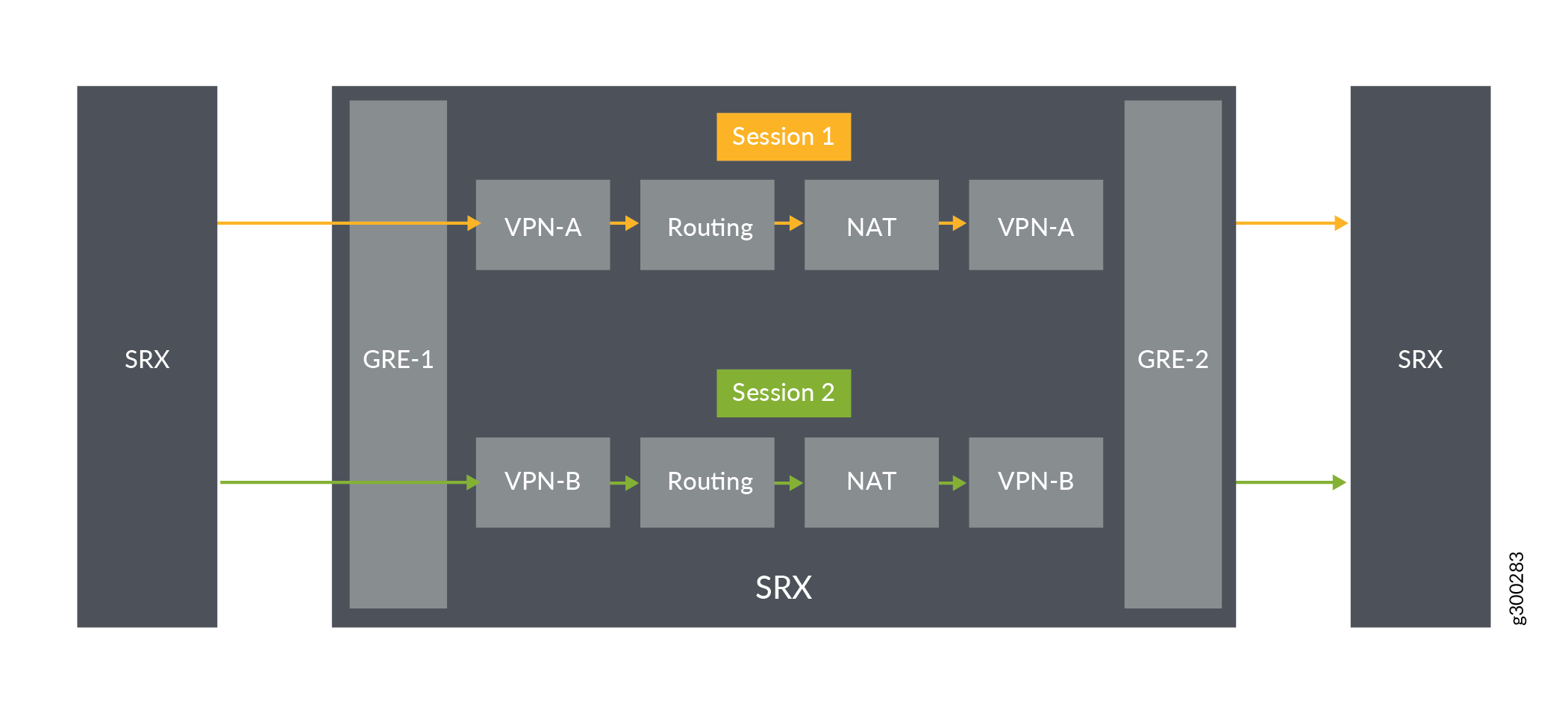
In Figure 8, an SRX Series Firewall is configured the routing group and permit traffic between MPLS networks using NAT. The SRX Series Firewall is configured with the VRF groups, vpn-A, vpn-A1, vpn-B, and vpn-B1.
Configuration
Procedure
CLI Quick Configuration
To quickly configure this example, copy the following commands, paste them into
a text file, remove any line breaks, change any details necessary to match your
network configuration, copy and paste the commands into the CLI at the
[edit] hierarchy level, and then enter
commit from configuration mode.
set security l3vpn vrf-group vpn-A vrf VRF-A1
set security l3vpn vrf-group vpn-A vrf VRF-A2
set security l3vpn vrf-group vpn-A1 vrf VRF-A11
set security l3vpn vrf-group vpn-A1 vrf VRF-A12
set security l3vpn vrf-group vpn-B vrf VRF-B1
set security l3vpn vrf-group vpn-B vrf VRF-B2
set security l3vpn vrf-group vpn-B1 vrf VRF-B11
set security l3vpn vrf-group vpn-B1 vrf VRF-B12
set security nat source pool vrf-a_p address 203.0.113.200
set security nat source rule-set vrf-a_rs from routing-group vpn-A
set security nat source rule-set vrf-a_rs to routing-group vpn-A1
set security nat source rule-set vrf-a_rs rule rule1 match source-address 192.168.1.200
set security nat source rule-set vrf-a_rs rule rule1 then source-nat pool vrf-a_p
set security nat source pool vrf-b_p address 203.0.113.201
set security nat source rule-set vrf-b_rs from routing-group vpn-B
set security nat source rule-set vrf-b_rs to routing-group vpn-B1
set security nat source rule-set vrf-b_rs rule rule2 match source-address 192.168.1.201
set security nat source rule-set vrf-b_rs rule rule2 then source-nat pool vrf-b_p
set security policies from-zone GRE-1_Zone to-zone GRE-2_Zone policy vrf-a_policy match source-address any
set security policies from-zone GRE-1_Zone to-zone GRE-2_Zone policy vrf-a_policy match destination-address any
set security policies from-zone GRE-1_Zone to-zone GRE-2_Zone policy vrf-a_policy match application any
set security policies from-zone GRE-1_Zone to-zone GRE-2_Zone policy vrf-a_policy match source-l3vpn-vrf-group vpn-A1
set security policies from-zone GRE-1_Zone to-zone GRE-2_Zone policy vrf-a_policy then permit
set security policies from-zone GRE-1_Zone to-zone GRE-2_Zone policy vrf-b_policy match source-address any
set security policies from-zone GRE-1_Zone to-zone GRE-2_Zone policy vrf-b_policy match destination-address any
set security policies from-zone GRE-1_Zone to-zone GRE-2_Zone policy vrf-b_policy match application any
set security policies from-zone GRE-1_Zone to-zone GRE-2_Zone policy vrf-b_policy match source-l3vpn-vrf-group vpn-B1
set security policies from-zone GRE-1_Zone to-zone GRE-2_Zone policy vrf-b_policy then permit
Step-by-Step Procedure
The following example requires you to navigate various levels in the configuration hierarchy. For information about navigating the CLI, see Using the CLI Editor in Configuration Mode in the CLI User Guide..
To configure source NAT mapping for a single VRF:
-
In Layer 3 VPNs create a VRF group vpn-A with VRF instances A1and A2.
[edit security]
user@host#set l3vpn vrf-group vpn-A vrf VRF-A1
user@host#set l3vpn vrf-group vpn-A vrf VRF-A2
-
In Layer 3 VPNs create a VRF group vpn-A1 with VRF instances A11and A12.
[edit security]
user@host#set l3vpn vrf-group vpn-A1 vrf VRF-A11
user@host#set l3vpn vrf-group vpn-A1 vrf VRF-A12
-
Create another VRF group vpn-B with VRF instances B1 and B2.
[edit security]
user@host#set l3vpn vrf-group vpn-B vrf VRF-B1
user@host#set l3vpn vrf-group vpn-B vrf VRF-B2
-
Create another VRF group vpn-B1 with VRF instances B11 and B12.
[edit security]
user@host#set l3vpn vrf-group vpn-B1 vrf VRF-B11
user@host#set l3vpn vrf-group vpn-B1 vrf VRF-B12
-
Specify a source NAT IP address pool.
[edit security nat source] user@host# set pool vrf-a_p address 192.168.1.200 user@host# set pool vrf-b_p address 192.168.1.201 -
Create a source NAT rule set.
[edit security nat source]
user@host# set rule-set rs from routing-group vpn-A
user@host# set rule-set rs from routing-group vpn-B
user@host# set rule-set rs to routing-group vpn-A1
user@host# set rule-set rs to routing-group vpn-B1
-
Configure a rule that matches packets and translates per VRF group network traffic to global IP pool.
[edit security nat source]
user@host# set rule-set rs rule vrf-a_rs match destination-address 203.0.113.200
user@host# set rule-set rs rule vrf-a_rs then destination-nat pool vrf-a_p
user@host# set rule-set rs rule vrf-b_rs match destination-address 203.0.113.201
user@host# set rule-set rs rule vrf-b_rs then destination-nat pool vrf-b_p
-
Create a security policy to permit vpn-A1 traffic.
[edit security policies from-zone GRE-1_Zone to-zone GRE-2_Zone]
user@host# set policy vrf-a_policy match source-address any
user@host# set policy vrf-a_policy match destination-address any
user@host# set policy vrf-a_policy match application any
user@host# set policy vrf-a_policy match destination-l3vpn-vrf-group vpn-A1
user@host# set policy vrf-a_policy then permit
-
Create a security policy to permit vpn-B1 traffic.
[edit security policies from-zone GRE-1_Zone to-zone GRE-2_Zone]
user@host# set policy vrf-b_policy match source-address any
user@host# set policy vrf-b_policy match destination-address any
user@host# set policy vrf-b_policy match application any
user@host# set policy vrf-b_policy match destination-l3vpn-vrf-group vpn-B1
user@host# set policy vrf-b_policy then permit
Results
From configuration mode, confirm your configuration by entering the show
security nat and show security policies commands. If
the output does not display the intended configuration, repeat the configuration
instructions in this example to correct it.
[edit]
user@host# show security nat
    source {
        pool vrf-a_p {
            address {
                203.0.113.200/32;
            }
        }
        pool vrf-b_p {
            address {
                203.0.113.201/32;
            }
        }
        rule-set vrf-a_rs {
            from routing-group vpn-A;
            to routing-group vpn-A1;
            rule rule1 {
                match {
                    source-address 192.168.1.200/32;
                }
                then {
                    source-nat {
                        pool {
                            vrf-a_p;
                        }
                    }
                }
            }
            rule-set vrf-b_rs {
                from routing-group vpn-B;
                to routing-group vpn-B1;
                match {
                    source-address 192.168.1.201/32;
                }
                then {
                    source-nat {
                        pool {
                            vrf-b_p;
                        }
                    }
                }
            }
        }
    }
[edit]
user@host# show security policies
from-zone GRE-1_Zone to-zone GRE-2_Zone {
    policy vrf-a_policy {
        match {
            source-address any;
            destination-address any;
            application any;
            destination-l3vpn-vrf-group vpn-A1;
        }
        then {
            permit;
        }
    }
    policy vrf-b_policy {
        match {
            source-address any;
            destination-address any;
            application any;
            destination-l3vpn-vrf-group vpn-B1;
        }
        then {
            permit;
        }
    }
}
If you are done configuring the device, enter commit from
configuration mode.
Verification
Verifying Security Policies
Purpose
Verify that there is traffic matching the source NAT rule.
Action
From operational mode, enter the show security nat source rule
all command. In the Translation hits field, verify whether there is
traffic that matches the destination NAT rule.
user@host> show security nat source rule all
Total source-nat rules: 2
Total referenced IPv4/IPv6 ip-prefixes: 2/0
Source NAT rule						: vrf-a_r
Rule-set										: rs
  Rule-Id                    : 1
  Rule position              : 1
  From routing-group         : vpn-A
  To zone                    : GE_Zone1
  Source addresses      		 : 203.0.113.200   - 203.0.113.200
  Action                     : vrf-a_p
  Translation hits           : 0
    Successful sessions      : 0
    Failed sessions          : 0
  Number of sessions         : 0
Source NAT rule						: vrf-b_r
 Rule-set									: rs
  Rule-Id                    : 2
  Rule position              : 2
  From routing-group         : vpn-A
  To zone                    : GE_Zone
  Destination addresses      : 203.0.113.201   - 203.0.113.201
  Action                     : vrf-b_p
  Translation hits           : 0
    Successful sessions      : 0
    Failed sessions          : 0
  Number of sessions         : 0
From operational mode, enter the show security policies
command to display a summary of all the security policies configured on the
device.
user@root> show security policies
Default policy: permit-all
From zone: GRE-1_Zone, To zone: GRE-2_Zone
  Policy: vrf-a_policy, State: enabled, Index: 4, Scope Policy: 0, Sequence number: 1
    Source L3VPN VRF Group: any
    destination L3VPN VRF Group: vpn-A1
    Source addresses: any
    Destination addresses: any
    Applications: any
    Action: permit
From zone: GRE-1_Zone, To zone: GRE-2_Zone
  Policy: vrf-b_policy, State: enabled, Index: 5, Scope Policy: 0, Sequence number: 2
    Source L3VPN VRF Group: any
    destination L3VPN VRF Group: vpn-B1
    Source addresses: any
    Destination addresses: any
    Applications: any
    Action: permit
Example: Configuring a Security Policy to Permit or Deny VRF-Based Traffic from MPLS Network to an IP Network using Source VRF Group
This example shows how to configure a security policy to permit traffic and deny traffic using the source VRF group.
Requirements
-
Understand how to create a security zone. SeeExample: Creating Security Zones .
-
Supported SRX Series Firewall with any supported Junos OS release. See Virtual Routing (VRF) and Security Policies.
-
Configure network interfaces on the device. See Interfaces User Guide for Security Devices.
Overview
In Junos OS, security policies enforce rules for transit traffic, in terms of what traffic can pass through the device and the actions that need to take place on the traffic as it passes through the device. In Figure 9, an SRX Firewall is deployed in an SD-WAN to control traffic using the source VRF group. Traffic from the GRE MPLS network is sent to site A and site B of the IP network. As per the network requirement, site A traffic should be denied, and only site B traffic should be permitted.
This configuration example shows how to:
-
Deny traffic from vpn-A (from GRE MPLS)
-
Permit traffic from vpn-B (from GRE MPLS)
Configuration
Procedure
CLI Quick Configuration
To quickly configure this example, copy the
following commands, paste them into a text file, remove any line breaks,
change any details necessary to match your network configuration,
copy and paste the commands into the CLI at the [edit] hierarchy
level, and then enter commit from configuration mode.
                     set security l3vpn vrf-group vpn-A vrf VRF-A1


                     set security l3vpn vrf-group vpn-A vrf VRF-A2


                     set security l3vpn vrf-group vpn-B vrf VRF-B1


                     set security l3vpn vrf-group vpn-B vrf VRF-B2


                     set security policies from-zone GRE_Zone to-zone GE_Zone policy vrf-a_policy match source-address any


                     set security policies from-zone GRE_Zone to-zone GE_Zone policy vrf-a_policy match destination-address any


                     set security policies from-zone GRE_Zone to-zone GE_Zone policy vrf-a_policy match application any


                     set security policies from-zone GRE_Zone to-zone GE_Zone policy vrf-a_policy match source-l3vpn-vrf-group vpn-A


                     set security policies from-zone GRE_Zone to-zone GE_Zone policy vrf-a_policy then deny


                     set security policies from-zone GRE_Zone to-zone GE_Zone policy vrf-b_policy match source-address any


                     set security policies from-zone GRE_Zone to-zone GE_Zone policy vrf-b_policy match destination-address any


                     set security policies from-zone GRE_Zone to-zone GE_Zone policy vrf-b_policy match application any


                     set security policies from-zone GRE_Zone to-zone GE_Zone policy vrf-b_policy match source-l3vpn-vrf-group vpn-B


                     set security policies from-zone GRE_Zone to-zone GE_Zone policy vrf-b_policy then permit
Step-by-Step Procedure
The following example requires you to navigate various levels in the configuration hierarchy. For information about navigating the CLI, see Using the CLI Editor in Configuration Mode in the Junos OS CLI User Guide.
-
Create VRF group vpn-A with VRF instances A1 and A2
[edit security] user@host# set l3vpn vrf-group vpn-A vrf VRF-A1 user@host# set l3vpn vrf-group vpn-A vrf VRF-A2 -
Create VRF group vpn-B with VRF instances B1 and B2
[edit security] user@host# set l3vpn vrf-group vpn-B vrf VRF-B1 user@host# set l3vpn vrf-group vpn-B vrf VRF-B2 -
Create a security policy to deny vpn-A traffic.
[edit security policies from-zone GRE_Zone to-zone GE_Zone] user@host# set policy vrf-a_policy match source-address any user@host# set policy vrf-a_policy match destination-address any user@host# set policy vrf-a_policy match application any user@host# set policy vrf-a_policy match source-l3vpn-vrf-group vpn-A user@host# set policy vrf-a_policy then deny -
Create a security policy to permit vpn-B traffic.
[edit security policies from-zone GRE_Zone to-zone GE_Zone]
user@host# set policy vrf-b_policy match source-address any
user@host# set policy vrf-b_policy match destination-address any
user@host# set policy vrf-b_policy match application any
user@host# set policy vrf-b_policy match source-l3vpn-vrf-group vpn-B
user@host# set policy vrf-b_policy then permit
Results
From configuration mode, confirm your configuration
by entering the show security policies and show routing-instances commands. If the output does not display the intended configuration,
repeat the configuration instructions in this example to correct it.
[edit]
user@host# show security policies
from-zone GRE_Zone to-zone GE_Zone {
    policy vrf-a_policy {
        match {
            source-address any;
            destination-address any;
            application any;
            source-l3vpn-vrf-group vpn-A;
        }
        then {
            deny;
        }
    }
    policy vrf-b_policy {
        match {
            source-address any;
            destination-address any;
            application any;
            source-l3vpn-vrf-group vpn-B;
        }
        then {
            permit;
        }
    }
If you are done configuring the device, enter commit from configuration mode.
Verification
Verifying Policy Configuration
Purpose
Verify information about security policies.
Action
From operational mode, enter the show security
policies command to display a summary of all the security policies
configured on the device.
user@root> show security policies
Default policy: permit-all
From zone: GRE_Zone, To zone: GE_Zone
  Policy: vrf-a_policy, State: enabled, Index: 4, Scope Policy: 0, Sequence number: 1
    Source L3VPN VRF Group: vpn-A
    destination L3VPN vrf-group: any
    Source addresses: any
    Destination addresses: any
    Applications: any
    Action: deny
  Policy: vrf-b_policy, State: enabled, Index: 5, Scope Policy: 0, Sequence number: 2
    Source L3VPN VRF Group: vpn-B
    destination L3VPN vrf-group: any
    Source addresses: any
    Destination addresses: any
    Applications: any
    Action: permit
Example: Configuring a Security Policy to Permit or Deny VRF-Based Traffic from an IP Network to MPLS Network using Destination VRF Group
This example shows how to configure a security policy to permit traffic and deny traffic using the source VRF group.
Requirements
-
Understand how to create a security zone. See Example: Creating Security Zones.
-
Supported SRX Series Firewall with any supported Junos OS release. See Virtual Routing (VRF) and Security Policies.
-
Configure network interfaces on the device. See Interfaces User Guide for Security Devices.
Overview
In Junos OS, security policies enforce rules for transit traffic, in terms of what traffic can pass through the device and the actions that need to take place on the traffic as it passes through the device. In Figure 10, an SRX Firewall is deployed in an SD-WAN to control traffic using the destination VRF group. Traffic from IP network is sent to site A and site B of the GRE MPLS network. As per the network requirement, site A traffic should be denied, and only site B traffic should be permitted.
This configuration example shows how to:
-
Deny traffic to vpn-A (to GRE MPLS)
-
Permit traffic to vpn-B (to GRE MPLS)
Configuration
Procedure
CLI Quick Configuration
To quickly configure this example, copy the
following commands, paste them into a text file, remove any line breaks,
change any details necessary to match your network configuration,
copy and paste the commands into the CLI at the [edit] hierarchy
level, and then enter commit from configuration mode.
                     set security l3vpn vrf-group vpn-A vrf VRF-A1


                     set security l3vpn vrf-group vpn-A vrf VRF-A2


                     set security l3vpn vrf-group vpn-B vrf VRF-B1


                     set security l3vpn vrf-group vpn-B vrf VRF-B2


                     set security policies from-zone LAN-a_Zone to-zone GRE_Zone policy vrf-a_policy match source-address any


                     set security policies from-zone LAN-a_Zone to-zone GRE_Zone policy vrf-a_policy match destination-address any


                     set security policies from-zone LAN-a_Zone to-zone GRE_Zone policy vrf-a_policy match application any


                     set security policies from-zone LAN-a_Zone to-zone GRE_Zone policy vrf-a_policy match destination-l3vpn-vrf-group vpn-A


                     set security policies from-zone LAN-a_Zone to-zone GRE_Zone policy vrf-a_policy then deny


                     set security policies from-zone LAN-b_Zone to-zone GRE_Zone policy vrf-b_policy match source-address any


                     set security policies from-zone LAN-b_Zone to-zone GRE_Zone policy vrf-b_policy match destination-address any


                     set security policies from-zone LAN-b_Zone to-zone GRE_Zone policy vrf-b_policy match application any


                     set security policies from-zone LAN-b_Zone to-zone GRE_Zone policy vrf-b_policy match destination-l3vpn-vrf-group vpn-B


                     set security policies from-zone LAN-b_Zone to-zone GRE_Zone policy vrf-b_policy then permit
Step-by-Step Procedure
The following example requires you to navigate various levels in the configuration hierarchy. For information about navigating the CLI, see Using the CLI Editor in Configuration Mode in the Junos OS CLI User Guide.
-
Create VRF group vpn-A with VRF instances A1 and A2
[edit security] user@host# set l3vpn vrf-group vpn-A vrf VRF-A1 user@host# set l3vpn vrf-group vpn-A vrf VRF-A2 -
Create VRF group vpn-B with VRF instances B1 and B2
[edit security] user@host# set l3vpn vrf-group vpn-B vrf VRF-B1 user@host# set l3vpn vrf-group vpn-B vrf VRF-B2 -
Create a security policy to deny vpn-A traffic.
[edit security policies from-zone LAN-a_Zone to-zone GRE_Zone] user@host# set policy vrf-a_policy match source-address any user@host# set policy vrf-a_policy match destination-address any user@host# set policy vrf-a_policy match application any user@host# set policy vrf-a_policy match destination-l3vpn-vrf-group vpn-A user@host# set policy vrf-a_policy then deny -
Create a security policy to permit vpn-B traffic.
[edit security policies from-zone LAN-b_Zone e to-zone GRE_Zone]
user@host# set policy vrf-b_policy match source-address any
user@host# set policy vrf-b_policy match destination-address any
user@host# set policy vrf-b_policy match application any
user@host# set policy vrf-b_policy match destination-l3vpn-vrf-group vpn-B
user@host# set policy vrf-b_policy then permit
Results
From configuration mode, confirm your configuration
by entering the show security policies and show routing-instances commands. If the output does not display the intended configuration,
repeat the configuration instructions in this example to correct it.
[edit]
user@host# show security policies
from-zone LAN-a_Zone  to-zone GRE_Zone {
    policy vrf-a_policy {
        match {
            source-address any;
            destination-address any;
            application any;
            destination-l3vpn-vrf-group vpn-A;
        }
        then {
            deny;
        }
    }
}
    from-zone LAN-b_Zone  to-zone GRE_Zone {
    policy vrf-b_policy {
        match {
            source-address any;
            destination-address any;
            application any;
            destination-l3vpn-vrf-group vpn-B;
        }
        then {
            permit;
        }
    }
}
If you are done configuring the device, enter commit from configuration mode.
Verification
Verifying Policy Configuration
Purpose
Verify information about security policies.
Action
From operational mode, enter the show security
policies command to display a summary of all the security policies
configured on the device.
user@root> show security policies
Default policy: permit-all
From zone:  LAN-a_Zone, To zone: GRE_Zone
  Policy: vrf-a_policy, State: enabled, Index: 4, Scope Policy: 0, Sequence number: 1
    Source L3VPN VRF Group: any
    destination L3VPN vrf-group: vpn-A
    Source addresses: any
    Destination addresses: any
    Applications: any
    Action: deny
 From zone:  LAN-b_Zone, To zone: GRE_Zone
	Policy: vrf-b_policy, State: enabled, Index: 5, Scope Policy: 0, Sequence number: 2
    Source L3VPN VRF Group: any
    destination L3VPN vrf-group: vpn-B
    Source addresses: any
    Destination addresses: any
    Applications: any
    Action: permit
Managing Overlapping VPN using VRF group
When there are two sessions in a L3VPN network, to avoid any conflicts between the two sessions VRF group-ID is added to session key as an additional key to differentiate the sessions.
In Figure 11 network1 and network3 are grouped together to VRF group-A in L3VPN network, and network2 and network4 are grouped together to VRF group-B. The sessions use VRF group-A and VRF group-B as differentiators.
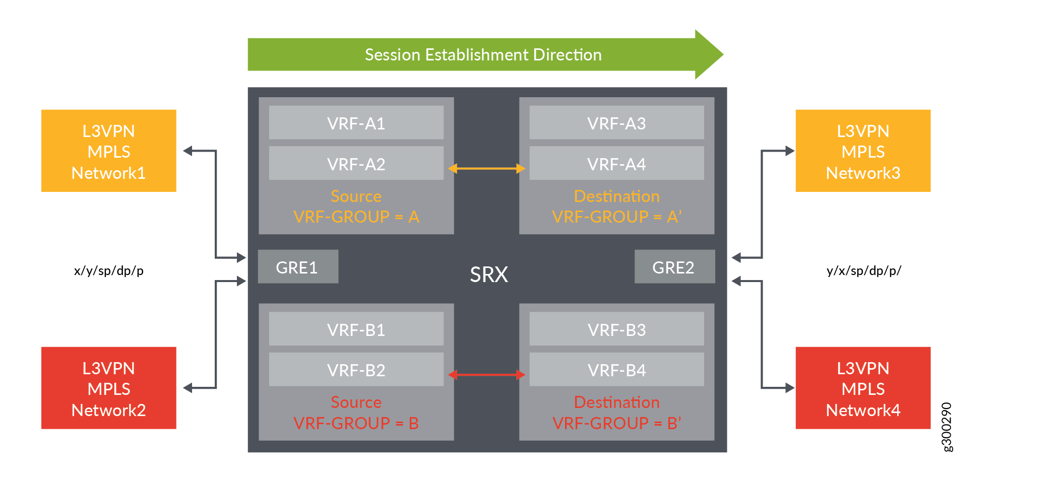
|
L3VPN Network 1 and 3 session |
L3VPN Network 2 and 4 session |
||
|---|---|---|---|
|
(Forward) |
(Reverse) |
(Forward) |
(Reverse) |
|
5-tuple: x/y/sp/dp/p |
5-tuple: y/x/dp/sp/p |
5-tuple: x/y/sp/dp/p |
5-tuple: y/x/dp/sp/p |
|
Token: GRE1(zone_id+VR_id) + VRF group-ID (A) |
Token: GRE1(zone_id+VR_id) + VRF group-ID (B) |
Token: GRE1(zone_id+VR_id) + VRF group-ID (A’) |
Token: GRE1(zone_id+VR_id) + VRF group-ID (B’) |