ON THIS PAGE
Understanding Session Traversal Utilities for NAT (STUN) Protocol
Understanding NAT64 IPv6 Prefix to IPv4 Address-Persistent Translation
Example: Supporting Network Configuration By Configuring Persistent NAT with Interface NAT
Example: Configuring Address-Dependent Filtering for IPv6 Clients
Example: Configuring Endpoint-Independent Filtering for IPv6 Clients
Example: Configuring Persistent NAT Hairpinning with Source NAT Pool with Address Shifting
Persistent NAT and NAT64
Network Address Translators (NATs) are well known to cause very significant problems with applications that carry IP addresses in the payload. Applications that suffer from this problem include VoIP and Multimedia Over IP. Persistent NAT improves NATs behavior and defines a set of NAT requirement behavior which is useful for VOIP applications working. NAT64 is a translating mechanism used to translate IPv6 packets to IPv4 packets and vice versa by translating the packet headers according to IP/ICMP Translation Algorithm.
Understanding Persistent NAT and NAT64
Persistent NAT allows applications to use the Session Traversal Utilities for NAT (STUN) protocol when passing through NAT firewalls. Persistent NAT ensures that all requests from the same internal transport address (internal IP address and port) are mapped to the same reflexive transport address (the public IP address and port created by the NAT device closest to the STUN server).
NAT64 is a mechanism for translating IPv6 packets to IPv4 packets and vice versa that allows IPv6 clients to contact IPv4 servers using unicast UDP, TCP, or ICMP. It is an enhancement of Network Address Translation-Protocol Translation (NAT-PT).
NAT64 supports the following:
-
Endpoint-independent mappings
-
Endpoint-independent filtering and address-dependent filtering
The mapping and filtering behaviors of NAT64 and persistent NAT are identical.
The following types of persistent NAT can be configured on the Juniper Networks device:
-
Any remote host—All requests from a specific internal IP address and port are mapped to the same reflexive transport address. Any external host can send a packet to the internal host by sending the packet to the reflexive transport address.
-
Target host—All requests from a specific internal IP address and port are mapped to the same reflexive transport address. An external host can send a packet to an internal host by sending the packet to the reflexive transport address. The internal host must have previously sent a packet to the external host’s IP address.
-
Target host port—All requests from a specific internal IP address and port are mapped to the same reflexive transport address. An external host can send a packet to an internal host by sending the packet to the reflexive transport address. The internal host must have previously sent a packet to the external host’s IP address and port.
The target-host-port configuration is not supported for NAT64 when configured with IPv6 address.
You configure any of the persistent NAT types with source NAT rules. The source NAT rule action can use a source NAT pool (with or without port translation) or an egress interface. Persistent NAT is not applicable for destination NAT, because persistent NAT bindings are based on outgoing sessions from internal to external.
Port overloading is used in Junos OS only for normal interface NAT traffic. Persistent
NAT does not support port overloading, and you must explicitly disable port overloading
with one of the following options at the [edit security nat source]
hierarchy level:
-
port-overloading off
-
port-overloading-factor 1
To configure security policies to permit or deny persistent NAT traffic, you can use two
new predefined services—junos-stun and
junos-persistent-nat.
Persistent NAT is different from the persistent address feature (see Understanding Persistent Addresses for Source NAT Pools). The persistent address feature applies to address mappings for source NAT pools configured on the device. The persistent NAT feature applies to address mappings on an external NAT device, and is configured for a specific source NAT pool or egress interface. Also, persistent NAT is intended for use with STUN client/server applications.
Use Feature Explorer to confirm platform and release support for specific features.
Review the Platform-Specific Persistent NAT Binding Support Behavior section for notes related to your platform.
Persistent NAT Dynamic Binding Scaling Limit
Persistent NAT dynamic scaling enables the system to expand NAT cone bindings up to a configured number of additional entries, based on the available runtime resources in the device. When you configure dynamic scaling, the device exceeds the current fixed NAT cone bindings limit per platform. Available memory in the device must be taken into consideration when you configure dynamic scaling limit.
For example, configuring the dynamic scaling limit to 1,000,000 bindings requires approximately 245–550 MB of memory.
Understanding Session Traversal Utilities for NAT (STUN) Protocol
Many video and voice applications do not work properly in a NAT environment. For example, Session Initiation Protocol (SIP), used with VoIP, encodes IP addresses and port numbers within application data. If a NAT firewall exists between the requestor and receiver, the translation of the IP address and port number in the data invalidates the information.
Also, a NAT firewall does not maintain a pinhole for incoming SIP messages. This forces the SIP application to either constantly refresh the pinhole with SIP messages or use an ALG to track registration, a function that may or may not be supported by the gateway device.
The Session Traversal Utilities for NAT (STUN) protocol, first defined in RFC 3489, Simple Traversal of User Datagram Protocol (UDP) Through Network Address Translators (NATs) and then later in RFC 5389, Session Traversal Utilities for NAT, is a simple client/server protocol. A STUN client sends requests to a STUN server, which returns responses to the client. A STUN client is usually part of an application that requires a public IP address and/or port. STUN clients can reside in an end system such as a PC or in a network server whereas STUN servers are usually attached to the public Internet.
Both the STUN client and STUN server must be provided by the application. Juniper Networks does not provide a STUN client or server.
The STUN protocol allows a client to:
Discover whether the application is behind a NAT firewall.
Determine the type of NAT binding being used.
Learn the reflexive transport address, which is the IP address and port binding allocated by NAT device closest to the STUN server. (There may be multiple levels of NAT between the STUN client and the STUN server.)
The client application can use the IP address binding information within protocols such as SIP and H.323.
Understanding NAT64 IPv6 Prefix to IPv4 Address-Persistent Translation
The NAT64 mechanism enables IPv6 clients to contact IPv4 servers by translating IPv6 addresses to IPv4 addresses (and vice versa). However, some IPv4 applications and services cannot work correctly over IPv6-only networks with standard NAT64 in a dual-translation scenario, such as 464XLAT. In those scenarios, address-persistent translation is required.
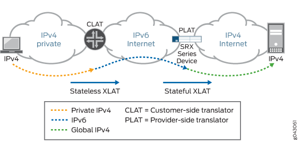
Figure 1 illustrates the 464XLAT architecture, whereby IPv4 packets are translated to IPv6 packets on the customer-side translator (CLAT), then go across the IPv6-only network, and are translated back to IPv4 packets on the provider-side translator (PLAT) to access global IPv4-only content in the core network. This architecture uses a combination of stateless translation on the CLAT and stateful translation on the PLAT.
When a device functions as a PLAT, it is responsible for keeping
the sticky mapping relationship between one specific IPv6 prefix and
one translated IPv4 address. The device treats the IPv6 prefix as
a single user. This mapping is accomplished by configuring the specific
IPv6 prefix length in an IPv4 source NAT pool using the address-persistent feature.
Figure 2 illustrates a NAT rule configured in the CLAT, which translates an IPv4 address to an IPv6 address with an address-persistent prefix. With stateless NAT46 translation on the CLAT and stateful NAT64 translation on the PLAT, the traffic from IPv4 host 192.168.1.2 reaches the global server 198.51.100.1 over an IPv6-only network.
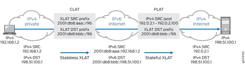
Table 1 lists other NAT features and their compatibility with the address-persistent feature.
|
Feature |
Compatible |
||
|---|---|---|---|
|
PAT pools |
IPv4 |
NAT IPv4 to IPv6 |
No |
|
NAT IPv6 to IPv4 |
Yes |
||
|
IPv6 |
NAT IPv4 to IPv6 |
No |
|
|
NAT IPv6 to IPv4 |
No |
||
|
Non-PAT pools |
No |
||
|
Port-overloading |
Yes |
||
|
Persistent NAT in PAT pool |
Yes |
||
|
Port block allocation |
Yes |
||
|
Deterministic NAT |
No |
||
|
Address pooling paired |
No |
||
|
ALG (Existing ALG NAT translations , such as FTP/PPTP/RTSP/DNS/SIP from native IPv6 clients.) |
Yes |
||
Persistent NAT and NAT64 Configuration Overview
To configure persistent NAT, specify the following options with the source NAT rule action (for either a source NAT pool or an egress interface):
The type of persistent NAT—One of the following: any remote host, target host, or target host port.
(Optional) Address mapping—This option allows requests from a specific internal IP address to be mapped to the same reflexive IP address; internal and reflexive ports can be any ports. An external host using any port can send a packet to the internal host by sending the packet to the reflexive IP address (with a configured incoming policy that allows external to internal traffic). If this option is not configured, the persistent NAT binding is for specific internal and reflexive transport addresses.
You can only specify the
address-mappingoption when the persistent NAT type is any remote host and the source NAT rule action is one of the following actions:Source NAT pool with IP address shifting
Source NAT pool with no port translation and no overflow pool
(Optional) Inactivity timeout—Time, in seconds, that the persistent NAT binding remains in the device’s memory when all the sessions of the binding entry have expired. When the configured timeout is reached, the binding is removed from memory. The default value is 300 seconds. Configure a value from 60 through 7200 seconds.
When all sessions of a persistent NAT binding have expired, the binding remains in a query state in the device’s memory for the specified inactivity timeout period. The query binding is automatically removed from memory when the inactivity timeout period expires (the default is 300 seconds). You can explicitly remove all or specific persistent NAT query bindings with the
clear security nat source persistent-nat-tablecommand.(Optional) Maximum session number—Maximum number of sessions with which a persistent NAT binding can be associated. The default is 30 sessions. Configure a value from 8 through 100.
For interface NAT, you need to explicitly disable port overloading
with one of the following options at the [edit security nat source] hierarchy level:
port-overloading off
port-overloading-factor 1
Finally, there are two predefined services that you can use in security policies to permit or deny STUN and persistent NAT traffic:
junos-stun—STUN protocol traffic.junos-persistent-nat—Persistent NAT traffic.
junos-persistent-nat policy at the end of your security policy
sequence. Alternatively, confirm that no subsequent policies match persistent NAT
traffic below the junos-persistent-nat policy.For the any remote host or target host or target host port persistent NAT type, the direction of the security policy is from internal to external.
Example: Configuring Address Persistent NAT64 Pools
This example shows how to configure address persistent NAT64 pools to ensure a sticky mapping relationship between one specific IPv6 prefix, which is calculated by the configured IPv6 prefix length, and one translated IPv4 address.
Requirements
Before you begin, be sure the existing NAT rules and pool configuration do not conflict with the new one.
Overview
In this example, you configure an IPv6 prefix length of /64 in an IPv4 source NAT pool for NAT IPv6 to IPv4 translations. Traffic matching the NAT rule and NAT pool perform address persistent translation between the IPv6 prefix and the IPv4 translated address. This configuration can be used on the provider-side translator (PLAT) in a dual-translation scenario, 464XLAT, to enable IPv4 services to work over IPv6-only networks.
Configuration
CLI Quick Configuration
To quickly configure this example, copy the
following commands, paste them into a text file, remove any line breaks,
change any details necessary to match your network configuration,
copy and paste the commands into the CLI at the [edit] hierarchy
level, and then enter commit from configuration mode.
set security  nat source pool NAT64 address 198.51.100.240/32 to 198.51.100.254/32
set security  nat source pool NAT64 address-persistent subscriber ipv6-prefix-length 64
set security  nat source rule-set RS1 from zone trust
set security  nat source rule-set RS1 to zone untrust
set security nat source rule-set RS1 rule R1 match source-address 2001:db8::/32
set security nat source rule-set RS1 rule R1 match destination-address 198.51.100.198/32
set security nat source rule-set RS1 rule R1 then source-nat pool NAT64
Procedure
Step-by-Step Procedure
The following example requires you to navigate throughout various levels in the configuration hierarchy. For instructions on how to do that, see Using the CLI Editor in Configuration Mode.
Create a source NAT pool.
[edit security nat source]
user@host# set pool NAT64 address 198.51.100.240/32 to 198.51.100.254/32
Specify the IPv6 prefix length for the source NAT pool.
[edit security nat source]
user@host# set pool NAT64 address-persistent subscriber ipv6-prefix-length 64
Create a rule set.
[edit security nat source]
user@host# set rule-set RS1 from zone trust
user@host# set rule-set RS1 to zone untrust
Match the rule.
[edit security nat source]
user@host# set rule-set RS1 rule R1 match source-address 2001:db8::/32
user@host# set rule-set RS1 rule R1 match destination-address 198.51.100.198/32
Provide the action to be performed when the rule matches.
[edit security nat source]
user@host# set security nat source rule-set RS1 rule R1 then source-nat pool NAT64
Results
From configuration mode, confirm your configuration
by entering the show security nat command. If the output
does not display the intended configuration, repeat the configuration
instructions in this example to correct it.
[edit]
user@host# show security nat
source {
    pool NAT64 {
        address {
            198.51.100.240/32 to 198.51.100.254/32;
        }
        address-persistent subscriber ipv6-prefix-length 64;
    }
    rule-set RS1 {
        from zone trust;
        to zone untrust;
        rule R1 {
            match {
                source-address 2001:db8::/32;
                destination-address 198.51.100.198/32;
            }
            then {
                source-nat {
                    pool {
                        NAT64;
                    }
                }
            }
        }
    }
}
If you are done configuring the device, enter commit from configuration mode.
Example: Supporting Network Configuration By Configuring Persistent NAT with Interface NAT
You can configure any of the persistent NAT types with source NAT rules. This example illustrates how to apply persistent NAT with an interface IP address and how to use an interface IP address as a NAT IP address to perform persistent NAT for a specific internal host. It also shows how to maintain persistent address port mapping behavior and persistent NAT filter behavior for the host. You must disable port overloading for interface NAT.
Requirements
This example uses the following hardware and software components:
1 Firewall
4 PCs
Before you begin:
Understand the concepts of persistent NAT. See Persistent NAT and NAT64 Configuration Overview.
Overview
In a Carrier Grade NAT (CGN) network deployment, you can configure the interface IP address as a NAT address to perform persistent network address translation. In this way, the internal host can create one source NAT mapping relationship by the outgoing traffic initiated from internal to external. Then the external host sends traffic back to this internal host by sending the traffic to this interface NAT address through the shared NAT mapping relationship.
In this example, you first configure the interface NAT rule
set int1 to match traffic from interface ge-0/0/1 to interface ge-0/0/2,
and then you configure the NAT rule in1 to match the specific source
and destination addresses to perform persistent NAT. You configure
the any remote host persistent NAT type when interface
NAT is performed.
For packets with source address 192.0.2.0/24 (internal phones)
and destination address 198.51.100.0/24 (including STUN server, SIP proxy
server, and external phones), you configure interface NAT with the any remote host persistent NAT type. Then you disable port
overloading for interface NAT.
Next, you configure a security policy to allow persistent NAT traffic from the external network (external zone) to the internal network (internal zone) for any of the remote host persistent NAT types.
Topology
Figure 3 shows an interface persistent NAT topology.
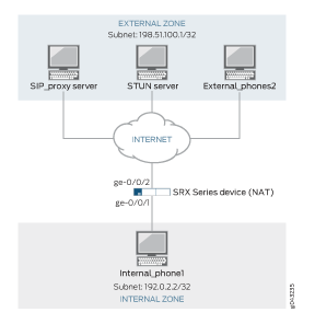
Table 2 shows the parameters configured in this example.
Parameter |
Description |
|---|---|
External Zone |
External network |
Internal Zone |
Internal network |
External_phones2 |
Phone2 address of external network |
Internal_phone1 |
Phone1 address of internal network |
SIP_proxy server |
SIP proxy server address of external network |
STUN server |
STUN server address of external network |
Subnet 198.51.100.1/32 |
Destination IP address |
Subnet 192.0.2.2/32 |
Source IP address |
ge-0/0/1 and ge-0/0/2 |
NAT interfaces for traffic direction |
Configuration
Procedure
CLI Quick Configuration
To quickly configure this example, copy the
following commands, paste them into a text file, remove any line breaks,
change any details necessary to match your network configuration,
copy and paste the commands into the CLI at the [edit] hierarchy
level, and then enter commit from configuration mode.
set security nat source rule-set int1 from interface ge-0/0/1.0
set security nat source rule-set int1 to interface ge-0/0/2.0
set security nat source rule-set int1 rule in1 match source-address 192.0.2.0/24
set security nat source rule-set int1 rule in1 match destination-address 198.51.100.0/24
set security nat source rule-set int1 rule in1 then source-nat interface persistent-nat permit any-remote-host
set security nat source interface port-overloading off
set security policies from-zone internal to-zone external policy stun_traffic match source-address internal_phones destination-address stun_server application junos-stun
set security policies from-zone internal to-zone external policy sip_proxy_traffic match source-address internal_phones destination-address sip_proxy_server application junos-sip
set security policies from-zone internal to-zone external policy sip_traffic match source-address internal_phones destination-address external_phones application junos-persistent-nat
set security policies from-zone internal to-zone external policy sip_traffic then permit
set security policies from-zone internal to-zone external policy stun_traffic then permit
set security policies from-zone internal to-zone external policy sip_proxy_traffic then permit
Step-by-Step Procedure
The following example requires you to navigate various levels in the configuration hierarchy. For instructions on how to do that, see Using the CLI Editor in Configuration Mode in the CLI User Guide.
To configure an interface NAT rule set:
Create a persistent NAT rule for an interface NAT.
[edit security nat source rule-set int1]
user@host# set from interface ge-0/0/1.0
user@host# set to interface ge-0/0/2.0
user@host# set rule in1 match source-address 192.0.2.0/24
user@host# set rule in1 match destination-address 198.51.100.0/24
user@host# set rule in1 then source-nat interface persistent-nat permit any-remote-host
Disable port overloading for interface NAT.
[edit security]
user@host# set nat source interface port-overloading off
Configure a security policy to allow STUN traffic from internal SIP phones to an external STUN server.
[edit security policies]
user@host# set from-zone internal to-zone external policy stun_traffic match source-address internal_phones destination-address stun_server application junos-stun
Configure a security policy to allow SIP proxy traffic from internal SIP phones to an external SIP proxy server.
[edit security policies]
user@host# set from-zone internal to-zone external policy sip_proxy_traffic match source-address internal_phones destination-address sip_proxy_server application junos-sip
Configure a security policy to allow SIP traffic from external SIP phones to internal SIP phones.
[edit security policies]
user@host# set from-zone internal to-zone external policy sip_traffic match source-address internal_phones destination-address external_phones application junos-persistent-nat
user@host# set from-zone internal to-zone external policy sip_traffic then permit
user@host#set from-zone internal to-zone external policy stun_traffic then permit
user@host#set from-zone internal to-zone external policy sip_proxy_traffic then permit
Results
From configuration mode, confirm your configuration
by entering the show security nat and show security
policies commands. If the output does not display the intended
configuration, repeat the instructions in this example to correct
the configuration.
[edit]
user@host# show security nat
source {
    interface {
        port-overloading off;
    }
    rule-set int1 {
        from interface ge-0/0/1.0;
        to interface ge-0/0/2.0;
        rule in1 {
            match {
                source-address 192.0.2.0/24;
                destination-address 198.51.100.0/24;
            }
            then {
                source-nat {
                    interface {
                        persistent-nat {
                            permit any-remote-host;
                        }
                    }
                }
            }
        }
    }
}
[edit]
user@host# show security policies
from-zone internal to-zone external {
    policy stun_traffic {
        match {
            source-address internal_phones;
            destination-address stun_server;
            application junos-stun;
        }
        then {
            permit;
        }
    }
    policy sip_proxy_traffic {
        match {
            source-address internal_phones;
            destination-address sip_proxy_server;
            application junos-sip;
        }
        then {
            permit;
        }
    }
    policy sip_traffic {
        match {
            source-address internal_phones;
            destination-address external_phones;
            application junos-persistent-nat;
        }
        then {
            permit;
        }
    }
}
If you are done configuring the device, enter commit from configuration mode.
Verification
Confirm that the configuration is working properly.
Verifying That Rules Are Matched and Used
Purpose
Verify that all the rules are matched and used.
Action
From operational mode, enter the show security
nat source persistent-nat-table all command.
user@host>show security nat source persistent-nat-table all
Internal  Reflective                 Source     Type           Left_time/Curr_Sess_Num/   Source
      In_IP     In_Port I_Proto Ref_IP     Ref_Port R_Proto NAT Pool  Conf_time Max_Sess_Num    NAT Rule
     192.0.2.12  17012   udp    198.51.100.1  28153     udp   interface  any-remote-host  3528/3600     -/-           in1
     192.0.2.12  7078    udp    198.51.100.1  6133      udp   interface  any-remote-host     -/300      1/30          in1
Meaning
The output displays a summary of persistent NAT information.
Verifying That NAT Traffic Sessions Are Established
Purpose
Verify that the sessions are established on the device.
Action
From operational mode, enter the show security
flow session command.
user@host>show security flow session

Session ID: 6992, Policy name: sip_proxy_traffic/5, Timeout: 16, Valid
  In: 192.0.2.12/17012 --> 198.51.100.45/5060;udp, If: ge-0/0/1.0, Pkts: 4, Bytes: 1850
  Out: 198.51.100.45/5060 --> 198.51.100.1/28153;udp, If: ge-0/0/2.0, Pkts: 5, Bytes: 2258

Session ID: 7382, Policy name: stun_traffic/4, Timeout: 16, Valid
  In: 192.0.2.12/7078 --> 198.51.100.49/3478;udp, If: ge-0/0/1.0, Pkts: 20, Bytes: 1040
  Out: 198.51.100.49/3478 --> 198.51.100.1/6133;udp, If: ge-0/0/2.0, Pkts: 0, Bytes: 0
Meaning
The show security flow session command displays
active sessions on the device and each session’s associated
security policy. The output shows traffic entering the device using
the private source address 192.0.2.12 destined to a public host at
198.51.100.45. The return traffic from this flow travels to the translated
public address 198.51.100.1.
Session ID—Number that identifies the session. Use this ID to get more information about the session such as policy name or number of packets in and out.
sip_proxy_traffic— Policy name that permitted the SIP traffic from the internal SIP phones to the external SIP proxy server.
In—Incoming flow (source and destination IP addresses with their respective source and destination port numbers. The session is UDP, and the source interface for this session is ge-0/0/1.0).
Out—Reverse flow (source and destination IP addresses with their respective source and destination port numbers. The session is UDP, and the destination interface for this session is ge-0/0/2.0).
stun_traffic—Policy name that permitted the STUN traffic from the internal SIP phones to the external STUN server.
Example: Configuring Address-Dependent Filtering for IPv6 Clients
This example shows how to configure address-dependent filtering for IPv6 clients using NAT64.
Requirements
Before you begin:
Ensure that IPv6 is enabled on the device.
Ensure that the existing NAT rule and pool configuration do not conflict with the new ones.
Overview
In this example you use NAT64 to send packets from the IPv6 internal host to the IPv4 external host and from the IPv4 external host to the IPv4 internal host.
Topology
Configuration
Procedure
CLI Quick Configuration
To quickly configure this example, copy the
following commands, paste them into a text file, remove any line breaks,
change any details necessary to match your network configuration,
copy and paste the commands into the CLI at the [edit] hierarchy
level, and then enter commit from configuration mode.
set security nat static rule-set test_rs from interface ge-0/0/1
set security nat static rule-set test_rs rule test_rule match destination-address 2001:db8::/128
set security nat static rule-set test_rs rule test_rule then static-nat prefix 10.2.2.15/32
set security nat source pool myipv4 address 203.0.113.2
set security nat source rule-set myipv4_rs from interface ge-0/0/1
set security nat source rule-set myipv4_rs to interface ge-0/0/2
set security nat source rule-set myipv4_rs rule ipv4_rule match source-address 2001:db8::/96
set security nat source rule-set myipv4_rs rule ipv4_rule match destination-address 10.2.2.15
set security nat source rule-set myipv4_rs rule ipv4_rule then source-nat pool myipv4
set security nat source rule-set myipv4_rs rule ipv4_rule then source-nat pool persistent-nat permit target-host
Step-by-Step Procedure
The following example requires you to navigate various levels in the configuration hierarchy. For instructions on how to do that, see Using the CLI Editor in Configuration Mode.
To configure address-dependent filtering for IPv6 clients:
Create a set of rules for NAT64.
[edit security nat static]
user@host# set rule-set test_rs from interface ge-0/0/1
Match the rule.
[edit security nat static]
user@host# set rule-set test_rs rule test_rule match destination-address 2001:db8::/128
Provide the action to be performed when the rule matches.
[edit security nat static]
user@host# set rule-set test_rs rule test_rule then static-nat prefix 10.2.2.15/32
Define a source address pool and add the address to the pool.
[edit security nat]
user@host# set source pool myipv4 address 203.0.113.2
Create another set of rules for NAT64.
[edit security nat]
user@host# set source rule-set myipv4_rs from interface ge-0/0/1
Match the rule with the source address.
[edit security nat]
user@host# set source rule-set myipv4_rs rule ipv4_rule match source-address 2001:db8::/96
Match the rule with the destination address.
[edit security nat]
user@host# set source rule-set myipv4_rs rule ipv4_rule match destination-address 10.2.2.15
Provide the action to be performed when the rules match.
[edit security nat]
user@host# set source rule-set myipv4_rs rule ipv4_rule then source-nat pool myipv4
Configure persistent NAT.
[edit security nat]
user@host# set source rule-set myipv4_rs rule ipv4_rule then source-nat pool persistent-nat permit target-host
Results
From configuration mode, confirm your configuration
by entering the show nat source command. If the output
does not display the intended configuration, repeat the configuration
instructions in this example to correct it.
[edit security]
user@host# show nat source
 pool myipv4 {
        address {
            203.0.113.2/32;
        }
    }
    rule-set test_rs {
        rule test_rule {
            match {
                destination-address 2001:db8::/128;
            }

        }

    }
    rule-set myipv4_rs {
        from interface ge-0/0/1.0;
        to interface ge-0/0/2.0;
        rule ipv4_rule {
            match {
                source-address 2001:db8::/96;
                destination-address 10.2.2.15/32;
            }
            then {
                source-nat {
                    pool {
                        myipv4;
                        persistent-nat {
                            permit target-host;
                        }
                    }
                }
            }
        }
    }
}
If you are done configuring the device, enter commit from configuration mode.
Verification
Confirm that the configuration is working properly:
Verifying That the Configuration Is Enabled and Working
Purpose
Verify that the configuration is enabled and working.
Action
From operational mode, enter the following commands:
show security nat static rule test_ruleshow security nat source rule ipv4_ruleshow security nat source pool myipv4
Example: Configuring Endpoint-Independent Filtering for IPv6 Clients
This example shows how to configure endpoint-independent filtering for IPv6 clients using NAT64.
Requirements
Before you begin:
Ensure that IPv6 is enabled on the device
Ensure that the existing NAT rules and pool configuration do not conflict with the new ones.
Overview
In this example you use NAT64 to send packets from the IPv6 internal host to the IPv4 external host and from the IPv4 external host to the IPv4 internal host.
Topology
Configuration
Procedure
CLI Quick Configuration
To quickly configure this example, copy the
following commands, paste them into a text file, remove any line breaks,
change any details necessary to match your network configuration,
copy and paste the commands into the CLI at the [edit] hierarchy
level, and then enter commit from configuration mode.
set security nat static rule-set test_rs from interface ge-0/0/1
set security nat static rule-set test_rs rule test_rule match destination-address 2001:db8::/128
set security nat static rule-set test_rs rule test_rule then static-nat prefix 10.2.2.15/32
set security nat source pool myipv4 address 203.0.113.2
set security nat source rule-set myipv4_rs from interface ge-0/0/1
set security nat source rule-set myipv4_rs to interface ge-0/0/2
set security nat source rule-set myipv4_rs rule ipv4_rule match source-address 2001:db8::/96
set security nat source rule-set myipv4_rs rule ipv4_rule match destination-address 10.2.2.15
set security nat source rule-set myipv4_rs rule ipv4_rule then source-nat pool myipv4
set security nat source rule-set myipv4_rs rule ipv4_rule then source-nat pool persistent-nat permit any-remote-host
Step-by-Step Procedure
The following example requires you to navigate various levels in the configuration hierarchy. For instructions on how to do that, see Using the CLI Editor in Configuration Mode.
To configure endpoint-independent filtering for IPv6 clients:
Create a set of rules for NAT64.
[edit security nat static]
user@host# set rule-set test_rs from interface ge-0/0/1
Match the rule.
[edit security nat static]
user@host# set rule-set test_rs rule test_rule match destination-address 2001:db8::/128
Provide the action to be performed when the rule matches.
[edit security nat static]
user@host# set rule-set test_rs rule test_rule then static-nat prefix 10.2.2.15/32
Define a source address pool and add the address to the pool.
[edit security nat]
user@host# set source pool myipv4 address 203.0.113.2
Create another set of rules for NAT64.
[edit security nat]
user@host# set source rule-set myipv4_rs from interface ge-0/0/1
Match the rule with the source address.
[edit security nat]
user@host# set source rule-set myipv4_rs rule ipv4_rule match source-address 2001:db8::/96
Match the rule with the destination address.
[edit security nat]
user@host# set source rule-set myipv4_rs rule ipv4_rule match destination-address 10.2.2.15
Provide the action to be performed when the rules match.
[edit security nat]
user@host# set source rule-set myipv4_rs rule ipv4_rule then source-nat pool myipv4
Configure persistent NAT.
[edit security nat]
user@host# set source rule-set myipv4_rs rule ipv4_rule then source-nat pool persistent-nat permit any-remote-host
Results
From configuration mode, confirm your configuration by entering the show security
nat command. If the output does not display the intended
configuration, repeat the configuration instructions in this example to
correct it.
[edit security]
user@host# show security nat
source {
pool myipv6_prefix {
address {
2001:db8::/64;
}
}
pool myipv4 {
address {
203.0.113.2/32;
}
}
rule-set myipv6_rs {
from interface ge-0/0/1.0;
to interface ge-0/0/2.0;
rule ipv6_rule {
match {
source-address 10.1.1.0/30;
destination-address 2001:db8::2/96;
}
then {
source-nat {
pool {
myipv6_prefix;
}
}
}
}
}
rule-set myipv4_rs {
from interface ge-0/0/1.0;
to interface ge-0/0/2.0;
rule ipv4_rule {
match {
source-address 2001:db8::/96;
destination-address 10.2.2.15/32;
}
then {
source-nat {
pool {
myipv4;
persistent-nat {
permit target-host;
}
}
}
}
}
}
}
static {
rule-set test_rs {
from interface ge-0/0/1.0;
rule test_rule {
match {
destination-address 2001:db8::/128;
}
then {
static-nat {
prefix {
10.2.2.15/32;
}
}
}
}
}
} If you are done configuring the device, enter commit from configuration mode.
Verification
Confirm that the configuration is working properly:
Verifying That the Configuration is Enabled and Working
Purpose
Verify that the configuration is enabled and working.
Action
From operational mode, enter the following commands.
show security nat static rule test_ruleshow security nat source rule ipv4_ruleshow security nat source pool myipv4
Example: Setting Maximum Persistent NAT Bindings
This example shows how to increase the persistent NAT capacity.
Requirements
Before you begin, see Understanding Persistent NAT and NAT64.
Overview
In this example, you enable the maximize persistent NAT capacity option. To enable this option, the supported central point maximum binding capacity can be approximately increased to 1/8 of the central point session capacity up to 2M and the supported SPU maximum binding capacity can be approximately increased to 1/4 of each SPU session capacity. Accordingly, the flow session capacity will decrease by 1/4 on both the CP and each of the SPU.
In
this example, you enable the session capacity to
maximum 20,000,000 on the central point and
maximum 1,100,000 on each of the SPUs with maximum
session configuration.
Use
the
maximize-persistent-nat-capacity
command.
Configuration
Procedure
Step-by-Step Procedure
To increase the persistent NAT capacity:
Set maximize persistent NAT capacity option.
[edit]
user@host# set security forwarding-process application-services maximize-persistent-nat-capacity
If you are done configuring the device, commit the configuration.
[edit]
user@host# commit
Restart the system from operational mode.
[edit]
user@host# request system reboot
When switching to maximize persistent NAT capacity mode or back to regular mode, you must restart the device.
If you want to switch the device back to regular mode, delete the maximize persistent NAT capacity mode configuration.
[edit]
user@host# delete security forwarding-process application-services maximize-persistent-nat-capacity
Persistent NAT Hairpinning Overview
When traffic is sent between two hosts, the source host of the traffic may only know the destination host by its public IP address. In reality, the destination host may be in the same private address space as the source host. Hairpinning is the process of returning the traffic in the direction from where it came from as a way to get it to its destination host in a private subnetwork.
Generally, a source host in a subnetwork may not recognize that the traffic is intended for a destination host within the same subnetwork, because it identifies the destination host only by its public IP address. The NAT analyzes the IP packets and routes the packet back to the correct host.
NAT hairpinning support is required if two hosts on the internal network want to communicate with each other by using a binding on the NAT device. In this case, the NAT device receives a packet from the internal network and forwards it back to the internal network. If hairpinning is not supported, forwarding the packet will fail and it will be dropped.
Hairpinning enables two endpoints (Host 1 and Host 2) on the private network to communicate even if they only use each other’s external IP addresses and ports. When Host 1 sends traffic to Host 3, a NAT binding between Host 1’s internal source IP address and port is associated in the NAT table with its external IP address and port. The same thing happens when Host 2 sends traffic to Host 3. In this way, when Host 1 and Host 2 want to communicate, they can identify each other’s external IP addresses.
For example, if Host 1 communicates with Host 2, NAT (with hairpinning support) is used to route the packets, which contain Host 2’s external address, back to Host 2’s internal address.
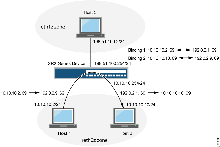
In Figure 4, the following parameters are used:
Host 1 IP address -
10.10.10.2/24Host 2 IP address -
10.10.10.10/24Intra-zone IP address -
10.10.10.254/24Host 3 IP address -
198.51.100.2/24Inter-zone IP address -
198.51.100.254/24Host 1 and Host 2 are in zone
reht0z, and Host 3 is inreth1zzone
Table 3 shows the binding table used in this example.
Original Source IP Address |
Translated Source IP Address |
|---|---|
10.10.10.2/24 to 10.10.10.11/24 |
192.0.2.1/32 to 192.0.2.10/32 |
Persistent NAT hairpinning applies only to any remote host persistent NAT type. To allow hairpinning, you must configure a security policy to allow traffic between endpoints in the same zone. Actually the two endpoints can be located in two different zones as well as long as either of the two hosts can only see the public address of the peer. NAT hairpinning behavior is not supported by target host persistent NAT and target host port persistent NAT. Only any remote host persistent NAT supports hairpinning behavior.
Example: Configuring Persistent NAT Hairpinning with Source NAT Pool with Address Shifting
This example shows how to configure persistent NAT hairpinning.
Requirements
Before you begin:
Configure network interfaces on the device. See Interfaces User Guide for Security Devices.
Create security zones and assign interfaces to them. See Understanding Security Zones.
Overview
Hairpinning allows packets from the private network to be translated and then looped back to the private network rather than being passed through to the public network. Hairpinning feature enables using a corresponding record in the NAT table to recognize that a packet is addressed to a host in the local network. Then it translates the destination IP address and sends the packet back to the local network (as well as in case of port mapping). This ensures that traffic between the two hosts work properly.
Topology
Hairpinning enables two endpoints (Host 1 and Host 2) on the private network to communicate even if they only use each other’s external IP addresses and ports. This is explained in Figure 5.
When Host 1 sends traffic to Host 3, a NAT binding between Host 1’s internal source IP address and port is associated in the NAT table with its external IP address and port. The same thing happens when Host 2 sends traffic to Host 3. In this way, when Host 1 and Host 2 want to communicate, they can identify each other’s external IP addresses.
For example, if Host 1 communicates with Host 2, NAT (with hairpinning support) is used to route the packets, which contain Host 2’s external address, back to Host 2’s internal address.

In Figure 5, the following parameters are used:
Host 1 IP address -
10.10.10.2/24Host 2 IP address -
10.10.10.10/24Intra-zone IP address -
10.10.10.254/24Host 3 IP address -
198.51.100.2/24Inter-zone IP address -
198.51.100.254/24Host 1 and Host 2 are in zone
reht0z, and Host 3 is inreth1zzone
Table 4 shows the binding table used in this example.
Original Source IP Address |
Translated Source IP Address |
|---|---|
10.10.10.2/24 to 10.10.10.11/24 |
192.0.2.1/32 to 192.0.2.10/32 |
Configuration
Procedure
Step-by-Step Procedure
To configure persistent NAT hairpinning:
Configure interfaces.
[edit]
user@host# set interfaces ge-11/0/0 unit 0 family inet address 10.10.10.254/24
user@host# set interfaces ge-11/0/1 unit 0 family inet address 198.51.100.254/24
Create zones (reth0z and reth1z).
[edit]
user@host# set security zones security-zone reth0z host-inbound-traffic system-services all
user@host# set security zones security-zone reth0z host-inbound-traffic protocols all
user@host# set security zones security-zone reth0z interfaces ge-11/0/0.0
user@host# set security zones security-zone reth1z host-inbound-traffic system-services all
user@host# set security zones security-zone reth1z host-inbound-traffic protocols all
user@host# set security zones security-zone reth1z interfaces ge-11/0/1.0
Create policies for zones reth0z and reth1z.
[edit]
user@host# set security address-book global address subnet10 10.10.10.0/24
user@host# set security address-book global address subnet20 198.51.100.0/24
user@host# set security policies from-zone reth0z to-zone reth1z policy p1 match source-address subnet10
user@host# set security policies from-zone reth0z to-zone reth1z policy p1 match destination-address subnet20
user@host# set security policies from-zone reth0z to-zone reth1z policy p1 match application any
user@host# set security policies from-zone reth0z to-zone reth1z policy p1 then permit
user@host# set security policies default-policy deny-all
Add same zone policy to do persistent NAT hairpinning.
user@host# set security policies from-zone reth0z to-zone reth0z policy p2 match source-address subnet10
user@host# set security policies from-zone reth0z to-zone reth0z policy p2 match destination-address subnet10
user@host# set security policies from-zone reth0z to-zone reth0z policy p2 match application any
user@host# set security policies from-zone reth0z to-zone reth0z policy p2 then permit
Create a source NAT pool for Host 1 and Host 2 (src1).
[edit]
user@host# set security nat source pool src1 address 192.0.2.1/32 to 192.0.2.10/32
Specify the beginning of the original source IP address range for Host 1 and Host 2 (src1).
[edit]
user@host# set security nat source pool src1 host-address-base 10.10.10.2/24
Configure the source NAT rule set r1.
[edit]
user@host# set security nat source rule-set r1 from zone reth0z
user@host# set security nat source rule-set r1 to zone reth1z
user@host# set security nat source rule-set r1 to zone reth0z
user@host# set security nat source rule-set r1 rule rule1 match source-address 10.10.10.0/24
user@host# set security nat source rule-set r1 rule rule1 match destination-address 10.10.10.0/24
user@host# set security nat source rule-set r1 rule rule1 match destination-address 198.51.100.0/24
user@host# set security nat source rule-set r1 rule rule1 then source-nat pool src1
user@host# set security nat source rule-set r1 rule rule1 then source-nat pool persistent-nat permit any-remote-host
user@host# set security nat source rule-set r1 rule rule1 then source-nat pool persistent-nat inactivity-timeout 900
user@host# set security nat source rule-set r1 rule rule1 then source-nat pool persistent-nat max-session-number 20
Results
From configuration mode, enter the show security
nat command to confirm your configuration. If the output does
not display the intended configuration, repeat the configuration instructions
in this example to correct it.
[edit]
user@host# show security nat
source {
    pool src1 {
        address {
            192.0.2.1/32 to 192.0.2.10/32;
        }
        host-address-base 10.10.10.2/24;
    }
    rule-set r1 {
        from zone reth0z;
        to zone [ reth0z reth1z ];
        rule rule1 {
            match {
                source-address 10.10.10.0/24;
                destination-address [10.10.10.0/24 198.51.100.0/24];
            }
            then {
                source-nat {
                    pool {
                        src1;
                        persistent-nat {
                            permit any-remote-host;
                            inactivity-timeout 900;
                            max-session-number 20;
                        }
                    }
                }
            }
        }
    }
}
If you are done configuring the device, enter commit from configuration mode.
Verification
- Traffic Sent Between the Hosts Creating Binding 1
- Traffic Sent Between the Hosts Creating Binding 2
- Traffic Sent Between Two Hosts
Traffic Sent Between the Hosts Creating Binding 1
Purpose
Verify traffic sent from between the hosts (Host 1 and Host 3) creating binding 1.
Action
 sendip -d r28 -p ipv4 -iv 4 -is 10.10.10.2 -id 198.51.100.2 -p udp -us 69 -ud 69 198.51.100.2

        Source-IP: 10.10.10.2
        Source-port: 69
        Dst-IP: 198.51.100.2
			 Dst-port: 69
        Binding1 is below:

user@host>show security nat source persistent-nat-table all
Internal   Reflective       Source            Type          Left_time/  Curr_Sess_Num/ Source
 In_IP     In_Port Ref_IP   Ref_Port NAT Pool                Conf_time   Max_Sess_Num  NAT Rule
10.10.10.2 69      192.0.2.1  69     src1     any-remote-host  -/900      1/20          rule1
Traffic Sent Between the Hosts Creating Binding 2
Purpose
Verify traffic sent from between the hosts (Host 2 and Host 3) creating binding 2.
Action
sendip -d r28 -p ipv4 -iv 4 -is 10.10.10.10 -id 198.51.100.2 -p udp -us 69 -ud 69 198.51.100.2
        Source-IP: 10.10.10.10
        Source-port: 69
        Dst-IP: 198.51.100.2
        Dst-port: 69
        Binding2 is below:


user@host>show security nat source persistent-nat-table all
Internal   Reflective          Source            Type            Left_time/  Curr_Sess_Num/  Source
 In_IP       In_Port Ref_IP    Ref_Port NAT Pool                  Conf_time   Max_Sess_Num   NAT Rule
10.10.10.2   69      192.0.2.1  69       src1     any-remote-host   -/900      1/20          rule1
10.10.10.10  69      192.0.2.9  69       src1     any-remote-host   -/900      1/20          rule1
Traffic Sent Between Two Hosts
Purpose
Verify the traffic sent from Host 1 to Host 2:
Action
user@host>show security flow session
sendip -d r28 -p ipv4 -iv 4 -is 10.10.10.2 -id 192.0.2.9 -p udp -us 69 -ud 69 192.0.2.9

  Session ID: 100007628, Policy name: default-policy/2, Timeout: 52, Valid
  In: 10.10.10.2/69 --> 192.0.2.9/69;udp, If: ge-0/0/0.0, Pkts: 2, Bytes: 112
  Out: 10.10.10.10/69 --> 192.0.2.1/69;udp, If: ge-0/0/0.0, Pkts: 0, Bytes: 0
   Total sessions: 1
Platform-Specific Persistent NAT Binding Support Behavior
Use Feature Explorer to confirm platform and release support for specific features.
Use the following table to review platform-specific behaviors for your platform:
| Platform | Difference |
|---|---|
| SRX Series |
|