Example: Configuring Automatic IP Multicast Without Explicit Tunnels
Understanding AMT
Automatic Multicast Tunneling (AMT) facilitates dynamic multicast connectivity between multicast-enabled networks across islands of unicast-only networks. Such connectivity enables service providers, content providers, and their customers to participate in delivering multicast traffic even if they lack end-to-end multicast connectivity.
AMT is supported on MX Series Ethernet Services Routers with Modular Port Concentrators (MPCs) that are running Junos 13.2 or later. AMT is also supported on i-chip based MPCs. AMT supports graceful restart (GR) but does not support graceful Routing Engine switchover (GRES).
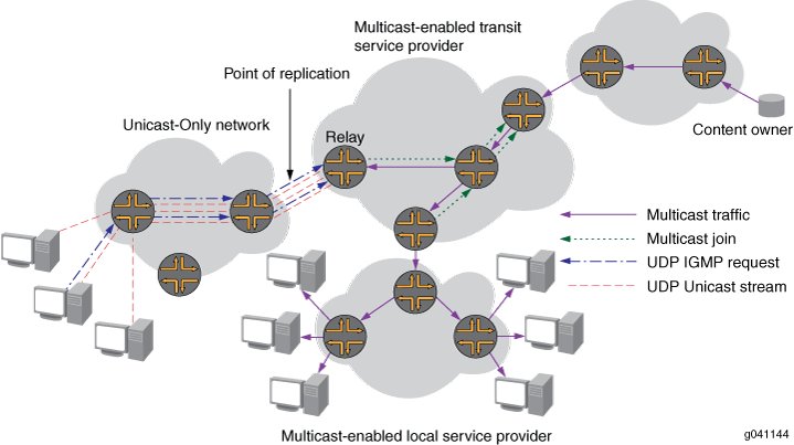
AMT dynamically establishes unicast-encapsulated tunnels between well-known multicast-enabled relay points (AMT relays) and network points reachable only through unicast (AMT gateways). Figure 1 shows the Automatic Multicast Tunneling Connectivity.
The AMT protocol provides discovery and handshaking between relays and gateways to establish tunnels dynamically without requiring explicit per-tunnel configuration.
AMT relays are typically routers with native IP multicast connectivity that aggregate a potentially large number of AMT tunnels.
The Junos OS implementation supports the following AMT relay functions:
-
IPv4 multicast traffic and IPv4 encapsulation
-
Well-known sources located on the multicast network
-
Prevention of denial-of-service attacks by quickly discarding multicast packets that are sourced through a gateway.
-
Per-route replication to the full fan-out of all AMT tunnels desired
-
The ability to collect normal interface statistics on AMT tunnels
Multicast sources located behind AMT gateways are not supported.
AMT supports PIM sparse mode. AMT does not support dense mode operation.
AMT Applications
Transit service providers have a challenge in the Internet because many local service providers are not multicast-enabled. The challenge is how to entice content owners to transmit video and other multicast traffic across their backbones. The cost model for the content owners might be prohibitively high if they have to pay for unicast streams for the majority of their subscribers.
Until more local providers are multicast-enabled, there is a transition strategy proposed by the Internet Engineering Task Force (IETF) and implemented in open source software. This strategy is called Automatic IP Multicast Without Explicit Tunnels (AMT). AMT involves setting up relays at peering points in multicast networks that can be reached from gateways installed on hosts connected to unicast networks.
Without AMT, when a user who is connected to a unicast-only network wants to receive multicast content, the content owner can allow the user to join through unicast. However, the content owner incurs an added cost because the owner needs extra bandwidth to support the unicast subscribers.
AMT allows any host to receive multicast. On the client end is an AMT gateway that is a single host. Once the gateway has located an AMT relay, which might be a host but is more typically a router, the gateway periodically sends Internet Group Management Protocol (IGMP) messages over a dynamically created UDP tunnel to the relay. AMT relays and gateways cooperate to transmit multicast traffic sourced within the multicast network to end-user sites. AMT relays receive the traffic natively and unicast-encapsulate it to gateways. This allows anyone on the Internet to create a dynamic tunnel to download multicast data streams.
With AMT, a multicast-enabled service provider can offer multicast services to a content owner. When a customer of the unicast-only local provider wants to receive the content and subscribes using an AMT join, the multicast-enabled transit provider can then efficiently transport the content to the unicast-only local provider, which sends it on to the end user.
AMT is an excellent way for transit service providers (who can get access to the content, but do not have many end users) to provide multicast service to content owners, where it would not otherwise be economically feasible. It is also a useful transition strategy for local service providers who do not yet have multicast support on all downstream equipment.
AMT is also useful for connecting two multicast-enabled service providers that are separated by a unicast-only service provider.
Similarly, AMT can be used by local service providers whose networks are multicast-enabled to tunnel multicast traffic over legacy edge devices such as digital subscriber line access multiplexers (DSLAMs) that have limited multicast capabilities.
Technical details of the implementation of AMT are as follows:
A three-way handshake is used to join groups from unicast receivers to prevent spoofing and denial-of-service (DoS) attacks.
An AMT relay acting as a replication server joins the multicast group and translates multicast traffic into multiple unicast streams.
The discovery mechanism uses anycast, enabling the discovery of the relay that is closest to the gateway in the network topology.
An AMT gateway acting as a client is a host that joins the multicast group.
Tunnel count limits on relays can limit bandwidth usage and avoid degradation of service.
AMT is described in detail in Internet draft draft-ietf-mboned-auto-multicast-10.txt, Automatic IP Multicast Without Explicit Tunnels (AMT).
AMT Operation
AMT is used to create multicast tunnels dynamically between multicast-enabled networks across islands of unicast-only networks. To do this, several steps occur sequentially.
The AMT relay (typically a router) advertises an anycast address prefix and route into the unicast routing infrastructure.
The AMT gateway (a host) sends AMT relay discovery messages to the nearest AMT relay reachable across the unicast-only infrastructure. To reduce the possibility of replay attacks or dictionary attacks, the relay discovery messages contain a cryptographic nonce. A cryptographic nonce is a random number used only once.
The closest relay in the topology receives the AMT relay discovery message and returns the nonce from the discovery message in an AMT relay advertisement message. This enables the gateway to learn the relay's unique IP address. The AMT relay now has an address to use for all subsequent (S,G), entries it will join.
The AMT gateway sends an AMT request message to the AMT relay's unique IP address to begin the process of joining the (S,G).
The AMT relay sends an AMT membership query back to the gateway.
The AMT gateway receives the AMT query message and sends an AMT membership update message containing the IGMP join messages.
The AMT relay sends a join message toward the source to build a native multicast tree in the native multicast infrastructure.
As packets are received from the source, the AMT relay replicates the packets to all interfaces in the outgoing interface list, including the AMT tunnel. The multicast traffic is then encapsulated in unicast AMT multicast data messages.
To maintain state in the AMT relay, the AMT gateway sends periodic AMT membership updates.
After the tunnel is established, the AMT tunnel state is refreshed with each membership update message sent. The timeout for the refresh messages is 240 seconds.
When the AMT gateway leaves the group, the AMT relay can free resources associated with the tunnel.
Note the following operational details:
The AMT relay creates an AMT pseudo interface (tunnel interface). AMT tunnel interfaces are implemented as generic UDP encapsulation (ud) logical interfaces. These logical interfaces have the identifier format ud-fpc/pic/port.unit.
All multicast packets (data and control) are encapsulated in unicast packets. UDP encapsulation is used for all AMT control and data packets using the IANA reserved UDP port number (2268) for AMT.
The AMT relay maintains a receiver list for each multicast session. The relay maintains the multicast state for each gateway that has joined a particular group or (S,G) pair.
Configuring the AMT Protocol
To configure the AMT protocol, include the amt statement:
amt {
    relay {
        accounting;
        family {
            inet {
                anycast-prefix ip-prefix</prefix-length>;
                local-address ip-address;
            }
        }
        secret-key-timeout minutes;
        tunnel-limit number;
    }
    traceoptions {
        file filename <files number> <size size> <world-readable | no-world-readable>;
        flag flag <flag-modifier> <disable>;
    }
}
You can include this statement at the following hierarchy levels:
[edit protocols][edit logical-systems logical-system-name protocols][edit routing-instances routing-instance-name protocols][edit logical-systems logical-system-name routing-instances routing-instance-name protocols]
In the following example, only the [edit protocols] hierarchy is identified.
The minimum configuration to enable AMT is to specify the AMT local address and the AMT anycast prefix.
See Also
Configuring Default IGMP Parameters for AMT Interfaces
You can optionally configure default IGMP parameters for all AMT tunnel interfaces.
Although, typically you do not need to change the values. To configure default IGMP attributes
of all AMT relay tunnels, include the amt statement:
amt { relay { defaults { (accounting | no-accounting); group-policy [ policy-names ]; query-interval seconds; query-response-interval seconds; robust-count number; ssm-map ssm-map-name; version version; } } }
You can include this statement at the following hierarchy levels:
[edit protocols igmp][edit logical-systems logical-system-name protocols igmp][edit routing-instances routing-instance-name protocols igmp][edit logical-systems logical-system-name routing-instances routing-instance-name protocols igmp]
The IGMP statements included at the [edit protocols igmp amt relay defaults] hierarchy level have the same syntax and purpose as IGMP statements included at the [edit protocols igmp] or [edit protocols igmp interface interface-name] hierarchy levels. These statements are as follows:
You can collect IGMP join and leave event statistics. To enable the collection of IGMP join and leave event statistics for all AMT interfaces, include the
accountingstatement:user@host# set protocols igmp amt relay defaults accounting
After enabling IGMP accounting, you must configure the router to filter the recorded information to a file or display it to a terminal. You can archive the events file.
To disable the collection of IGMP join and leave event statistics for all AMT interfaces, include the
no-accountingstatement:user@host# set protocols igmp amt relay defaults no-accounting
You can filter unwanted IGMP reports at the interface level. To filter unwanted IGMP reports, define a policy to match only IGMP group addresses (for IGMPv2) by using the policy's
route-filterstatement to match the group address. Define the policy to match IGMP (S,G) addresses (for IGMPv3) by using the policy'sroute-filterstatement to match the group address and the policy'ssource-address-filterstatement to match the source address. In the following example, the amt_reject policy is created to match both the group and source addresses.user@host# set policy-options policy-statement amt_reject from route-filter 224.1.1.1/32 exact user@host# set policy-options policy-statement amt_reject from source-address-filter 192.168.0.0/16 orlonger user@host# set policy-options policy-statement amt_reject then reject
To apply the IGMP report filtering on the interface where you prefer not to receive specific group or (S,G) reports, include the
group-policystatement. The following example applies the amt_reject policy to all AMT interfaces.user@host# set protocols igmp amt relay defaults group-policy amt_reject
You can change the IGMP query interval for all AMT interfaces to reduce or increase the number of host query messages sent. In AMT, host query messages are sent in response to membership request messages from the gateway. The query interval configured on the relay must be compatible with the membership request timer configured on the gateway. To modify this interval, include the
query-intervalstatement. The following example sets the host query interval to 250 seconds.user@host# set protocols igmp amt relay defaults query-interval 250
The IGMP querier router periodically sends general host-query messages. These messages solicit group membership information and are sent to the all-systems multicast group address, 224.0.0.1.
You can change the IGMP query response interval. The query response interval multiplied by the robust count is the maximum amount of time that can elapse between the sending of a host query message by the querier router and the receipt of a response from a host. Varying this interval allows you to adjust the number of IGMP messages on the AMT interfaces. To modify this interval, include the
query-response-intervalstatement. The following example configures the query response interval to 20 seconds.user@host# set protocols igmp amt relay defaults query-response-interval 20
You can change the IGMP robust count. The robust count is used to adjust for the expected packet loss on the AMT interfaces. Increasing the robust count allows for more packet loss but increases the leave latency of the subnetwork. To modify the robust count, include the
robust-countstatement. The following example configures the robust count to 3.user@host# set protocols igmp amt relay defaults robust-count 3
The robust count automatically changes certain IGMP message intervals for IGMPv2 and IGMPv3.
On a shared network running IGMPv2, when the query router receives an IGMP leave message, it must send an IGMP group query message for a specified number of times. The number of IGMP group query messages sent is determined by the robust count. The interval between query messages is determined by the last member query interval. Also, the IGMPv2 query response interval is multiplied by the robust count to determine the maximum amount of time between the sending of a host query message and receipt of a response from a host.
For more information about the IGMPv2 robust count, see RFC 2236, Internet Group Management Protocol, Version 2.
In IGMPv3 a change of interface state causes the system to immediately transmit a state-change report from that interface. If the state-change report is missed by one or more multicast routers, it is retransmitted. The number of times it is retransmitted is the robust count minus one. In IGMPv3 the robust count is also a factor in determining the group membership interval, the older version querier interval, and the other querier present interval.
For more information about the IGMPv3 robust count, see RFC 3376, Internet Group Management Protocol, Version 3.
You can apply a source-specific multicast (SSM) map to an AMT interface. SSM mapping translates IGMPv1 or IGMPv2 membership reports to an IGMPv3 report, which allows hosts running IGMPv1 or IGMPv2 to participate in SSM until the hosts transition to IGMPv3.
SSM mapping applies to all group addresses that match the policy, not just those that conform to SSM addressing conventions (232/8 for IPv4).
In this example, you create a policy to match the 232.1.1.1/32 group address for translation to IGMPv3. Then you define the SSM map that associates the policy with the 192.168.43.66 source address where these group addresses are found. Finally, you apply the SSM map to all AMT interfaces.
user@host# set policy-options policy-statement ssm-policy-example term A from route-filter 232.1.1.1/32 exact user@host# set policy-options policy-statement ssm-policy-example term A then accept user@host# set routing-options multicast ssm-map ssm-map-example policy ssm-policy-example user@host# set routing-options multicast ssm-map ssm-map-example source 192.168.43.66 user@host# set protocols igmp amt relay defaults ssm-map ssm-map-example
See Also
Example: Configuring the AMT Protocol
This example shows how to configure the Automatic Multicast Tunneling (AMT) Protocol to facilitate dynamic multicast connectivity between multicast-enabled networks across islands of unicast-only networks.
Requirements
Before you begin:
Configure the router interfaces.
Configure an interior gateway protocol or static routing. See the Junos OS Routing Protocols Library.
Configure a multicast group membership protocol (IGMP or MLD). See Understanding IGMP and Understanding MLD.
Overview
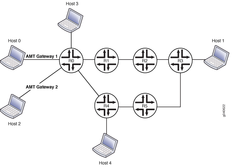
In this example, Host 0 and Host 2 are multicast receivers in a unicast cloud. Their default gateway devices are AMT gateways. R0 and R4 are configured with unicast protocols only. R1, R2, R3, and R5 are configured with PIM multicast. Host 1 is a source in a multicast cloud. R0 and R5 are configured to perform AMT relay. Host 3 and Host 4 are multicast receivers (or sources that are directly connected to receivers). This example shows R1 configured with an AMT relay local address and an anycast prefix as its own loopback address. The example also shows R0 configured with tunnel services enabled.
Configuration
CLI Quick Configuration
To quickly configure this example, copy the
following commands, paste them into a text file, remove any line breaks,
change any details necessary to match your network configuration,
copy and paste the commands into the CLI at the [edit] hierarchy
level, and then enter commit from configuration mode.
set protocols amt traceoptions file amt.log set protocols amt traceoptions flag errors set protocols amt traceoptions flag packets detail set protocols amt traceoptions flag route detail set protocols amt traceoptions flag state detail set protocols amt traceoptions flag tunnels detail set protocols amt relay family inet anycast-prefix 10.10.10.10/32 set protocols amt relay family inet local-address 10.255.112.201 set protocols amt relay tunnel-limit 10 set protocols pim interface all mode sparse-dense set protocols pim interface all version 2 set protocols pim interface fxp0.0 disable set chassis fpc 0 pic 0 tunnel-services bandwidth 1g
Procedure
Step-by-Step Procedure
The following example requires you to navigate various levels in the configuration hierarchy. For information about navigating the CLI, see Using the CLI Editor in Configuration Mode in the Junos OS CLI User Guide.
To configure the AMT protocol on R1:
Configure AMT tracing operations.
[edit protocols amt traceoptions] user@host# set file amt.log user@host# set flag errors user@host# set flag packets detail user@host# set flag route detail user@host# set flag state detail user@host# set flag tunnels detail
Configure the AMT relay settings.
[edit protocols amt relay] user@host# set relay family inet anycast-prefix 10.10.10.10/32 user@host# set family inet local-address 10.255.112.201 user@host# set tunnel-limit 10
Configure PIM on R1’s interfaces.
[edit protocols pim]
set interface all mode sparse-dense
set interface all version 2
set interface fxp0.0 disable
Enable tunnel functionality.
[edit chassis]
set fpc 0 pic 0 tunnel-services bandwidth 1g
If you are done configuring the device, commit the configuration.
user@host# commit
Results
From configuration mode, confirm your configuration by entering the show chassis and show protocols commands. If the output does not display the intended configuration, repeat the instructions in this example to correct the configuration.
user@host# show chassis
fpc 0 {
    pic 0 {
        tunnel-services {
            bandwidth 1g;
        }
    }
}
user@host# show protocols
amt {
    traceoptions {
        file amt.log;
        flag errors;
        flag packets detail;
        flag route detail;
        flag state detail;
        flag tunnels detail;
    }
    relay {
        family {
            inet {
                anycast-prefix 10.10.10.10/32;
                local-address 10.255.112.201;
            }
        }
        tunnel-limit 10;
    }
}
pim {
    interface all {
        mode sparse-dense;
        version 2;
    }
    interface fxp0.0 {
        disable;
    }
}
Verification
To verify the configuration, run the following commands:
show amt statistics
show amt summary
show amt tunnel