Enabling Next-Generation MVPN Services
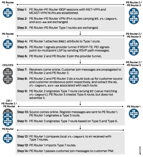
Juniper Networks introduced the industry’s first implementation of BGP next-generation multicast virtual private networks (MVPNs). See Figure 1 for a summary of a Junos OS next-generation MVPN routing flow.
Next-generation MVPN services are configured on top of BGP-MPLS unicast VPN services.
You can configure a Juniper Networks PE router that is already providing unicast BGP-MPLS VPN connectivity to support multicast VPN connectivity in three steps:
-
Configure the provider edge (PE) routers to support the BGP multicast VPN address family by including the
signalingstatement at the[edit protocols bgp group group-name family inet-mvpn]hierarchy level. This address family enables PE routers to exchange MVPN routes. -
Configure the PE routers to support the MVPN control plane tasks by including the
mvpnstatement at the[edit routing-instances routing-instance-name protocols]hierarchy level. This statement signals PE routers to initialize the MVPN module that is responsible for the majority of next-generation MVPN control plane tasks. -
Configure the sender PE router to signal a provider tunnel by including the
provider-tunnelstatement at the[edit routing-instances routing-instance-name]hierarchy level. You must also enable the tunnel signaling protocol (RSVP-TE or P-PIM) if it is not part of the unicast VPN service configuration. To enable the tunnel signaling protocol, include thersvp-teorpim-asmstatements at the[edit routing-instances routing-instance-name provider-tunnel]hierarchy level.
After these three statements are configured and each PE router has established internal BGP (IBGP) sessions using both INET-VPN and MCAST-VPN address
families, four routing tables are automatically created. These tables are bgp.l3vpn.0, bgp.mvpn.0, <routing-instance-name>.inet.0,
and <routing-instance-name>.mvpn.0. See Table 1
|
Automatically Generated Routing Table |
Description |
|---|---|
|
bgp.l3vpn.0 |
Populated with VPN-IPv4 routes received from remote PE routers via the INET-VPN address family. The routes in the |
|
bgp.mvpn.0 |
Populated by MVPN routes (Type 1 – Type 7). Received from remote PE routers via the MCAST-VPN address family. Routes in this table carry one or more routing table communities. |
|
<routing-instance-name>.inet.0 |
Populated by local and remote VPN unicast routes. The local VPN routes are typically learned from local CE routers via protocols such as BGP,
OSPF, and RIP, or via a static configuration. The remote VPN routes are imported from the |
|
<routing-instance-name>.mvpn.0 |
Populated by local and remote MVPN routes. The local MVPN routes are typically the locally originated routes, such as Type 1 intra-AS autodiscovery
routes, or Type 7 C-multicast routes. The remote MVPN routes are imported from the |