Understanding Next-Generation MVPN Network Topology
Layer 3 BGP-MPLS virtual private networks (VPNs) are widely deployed in today’s networks worldwide. Multicast applications, such as IPTV, are rapidly gaining popularity as is the number of networks with multiple, media-rich services merging over a shared Multiprotocol Label Switching (MPLS) infrastructure. The demand for delivering multicast service across a BGP-MPLS infrastructure in a scalable and reliable way is also increasing.
RFC 4364 describes protocols and procedures for building unicast BGP-MPLS VPNs. However, there is no framework specified in the RFC for provisioning multicast VPN (MVPN) services. In the past, Multiprotocol Label Switching Virtual Private Network (MVPN) traffic was overlaid on top of a BGP-MPLS network using a virtual LAN model based on Draft Rosen. Using the Draft Rosen approach, service providers were faced with control and data plane scaling issues of an overlay model and the maintenance of two routing/forwarding mechanisms: one for VPN unicast service and one for VPN multicast service. For more information about the limitations of Draft Rosen, see draft-rekhter-mboned-mvpn-deploy.
As a result, the IETF Layer 3 VPN working group published an Internet draft draft-ietf-l3vpn-2547bis-mcast-10.txt, Multicast in MPLS/BGP IP VPNs, that outlines a different architecture for next-generation MVPNs, as well as an accompanying RFC 2547 that proposes a BGP control plane for MVPNs. In turn, Juniper Networks delivered the industry’s first implementation of BGP next-generation MVPNs in 2007.
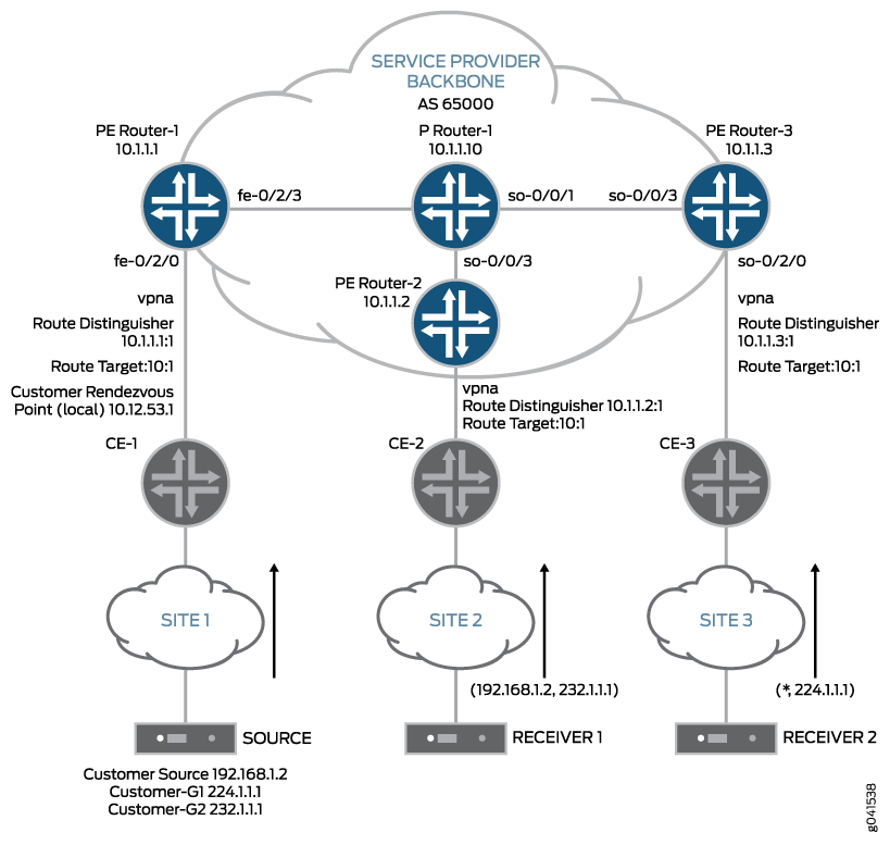
All examples in this document refer to the network topology shown in Figure 1:
-
The service provider in this example offers VPN unicast and multicast services to Customer A (vpna).
-
The VPN multicast source is connected to Site 1 and transmits data to groups 232.1.1.1 and 224.1.1.1.
-
VPN multicast receivers are connected to Site 2 and Site 3.
-
The provider edge router 1 (Router PE1) VRF table acts as the C-RP (using address 10.12.53.1) for C-PIM-SM ASM groups.
-
The service provider uses RSVP-TE point-to-multipoint LSPs for transmitting VPN multicast data across the network.
Figure 1: Next-Generation MVPN Topology
