Example: Configuring Sender-Based RPF in a BGP MVPN with MLDP Point-to-Multipoint Provider Tunnels
This example shows how to configure sender-based reverse-path forwarding (RPF) in a BGP multicast VPN (MVPN). Sender-based RPF helps to prevent multiple provider edge (PE) routers from sending traffic into the core, thus preventing duplicate traffic being sent to a customer.
Requirements
No special configuration beyond device initialization is required before configuring this example.
Sender-based RPF is supported only for MPLS BGP MVPNs with RSVP-TE point-to-multipoint provider tunnels. Both SPT-only and SPT-RPT MVPN modes are supported.
Sender-based RPF does not work when point-to-multipoint provider tunnels are used with label-switched interfaces (LSI). Junos OS only allocates a single LSI label for each VRF, and uses this label for all point-to-multipoint tunnels. Therefore, the label that the egress receives does not indicate the sending PE router. LSI labels currently cannot scale to create a unique label for each point-to-multipoint tunnel. As such, virtual tunnel interfaces (vt) must be used for sender-based RPF functionality with point-to-multipoint provider tunnels.
This example requires Junos OS Release 21.1R1 or later on the PE router that has sender-based RPF enabled.
Overview
This example shows a single autonomous system (intra-AS scenario) in which one source sends multicast traffic (group 224.1.1.1) into the VPN (VRF instance vpn-1). Two receivers subscribe to the group. They are connected to Device CE2 and Device CE3, respectively. MLDP point-to-multipoint LSPs with inclusive provider tunnels are set up among the PE routers. PIM (C-PIM) is configured on the PE-CE links.
For MPLS, the signaling control protocol used here is LDP. Optionally, you can use RSVP to signal both point-to-point and point-to-point tunnels.
OSPF is used for interior gateway protocol (IGP) connectivity, though IS-IS is also a supported option. If you use OSPF, you must enable OSPF traffic engineering.
For testing purposes, routers are used to simulate the source and the receivers.
Device PE2 and Device PE3 are configured to statically join the 224.1.1.1 group by
using the set protocols igmp interface interface-name
static group 224.1.1.1 command. In the case when a real multicast
receiver host is not available, as in this example, this static IGMP configuration
is useful. On the CE devices attached to the receivers, to make them listen to the
multicast group address, the example uses set protocols sap listen
224.1.1.1. A ping command is used to send multicast traffic into the
BGP MBPN.
Sender-based RPF is enabled on Device PE2, as follows:
[routing-instances vpn-1 protocols mvpn]
user@PE2# set sender-based-rpf
You can optionally configure hot-root-standby with
sender-based-rpf.
Topology
Figure 1 shows the sample network.
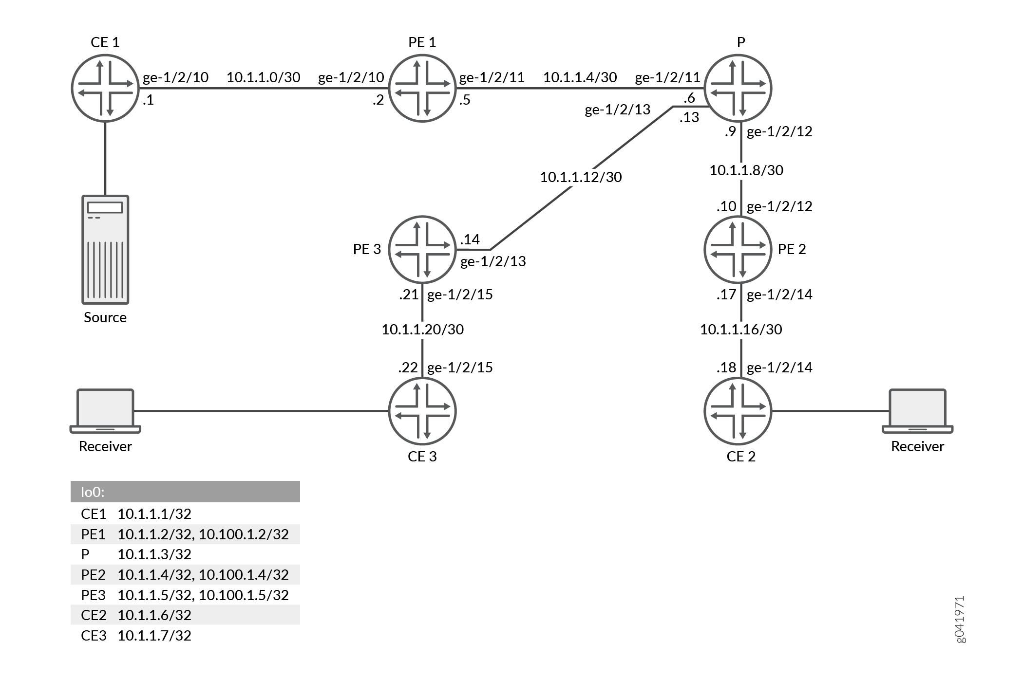
Set Commands for All Devices in the Topology shows the configuration for all of the devices in Figure 1.
The section Configuring Device PE2 describes the steps on Device PE2.
Set Commands for All Devices in the Topology
CLI Quick Configuration
To quickly configure this example, copy the following commands, paste them into a
text file, remove any line breaks, change any details necessary to match your
network configuration, and then copy and paste the commands into the CLI at the
[edit] hierarchy level.
Device CE1
set interfaces ge-1/2/10 unit 0 family inet address 10.1.1.1/30
set interfaces ge-1/2/10 unit 0 family mpls
set interfaces lo0 unit 0 family inet address 10.1.1.1/32
set protocols ospf area 0.0.0.0 interface lo0.0 passive
set protocols ospf area 0.0.0.0 interface ge-1/2/10.0
set protocols pim rp static address 10.100.1.2
set protocols pim interface all
set routing-options router-id 10.1.1.1
Device CE2
set interfaces ge-1/2/14 unit 0 family inet address 10.1.1.18/30
set interfaces ge-1/2/14 unit 0 family mpls
set interfaces lo0 unit 0 family inet address 10.1.1.6/32
set protocols sap listen 224.1.1.1
set protocols ospf area 0.0.0.0 interface lo0.0 passive
set protocols ospf area 0.0.0.0 interface ge-1/2/14.0
set protocols pim rp static address 10.100.1.2
set protocols pim interface all
set routing-options router-id 10.1.1.6
Device CE3
set interfaces ge-1/2/15 unit 0 family inet address 10.1.1.22/30
set interfaces ge-1/2/15 unit 0 family mpls
set interfaces lo0 unit 0 family inet address 10.1.1.7/32
set protocols sap listen 224.1.1.1
set protocols ospf area 0.0.0.0 interface lo0.0 passive
set protocols ospf area 0.0.0.0 interface ge-1/2/15.0
set protocols pim rp static address 10.100.1.2
set protocols pim interface all
set routing-options router-id 10.1.1.7
Device P
set interfaces ge-1/2/11 unit 0 family inet address 10.1.1.6/30
set interfaces ge-1/2/11 unit 0 family mpls
set interfaces ge-1/2/12 unit 0 family inet address 10.1.1.9/30
set interfaces ge-1/2/12 unit 0 family mpls
set interfaces ge-1/2/13 unit 0 family inet address 10.1.1.13/30
set interfaces ge-1/2/13 unit 0 family mpls
set interfaces lo0 unit 0 family inet address 10.1.1.3/32
set protocols rsvp interface all
set protocols mpls traffic-engineering bgp-igp-both-ribs
set protocols mpls interface ge-1/2/11.0
set protocols mpls interface ge-1/2/12.0
set protocols mpls interface ge-1/2/13.0
set protocols ospf traffic-engineering
set protocols ospf area 0.0.0.0 interface lo0.0 passive
set protocols ospf area 0.0.0.0 interface ge-1/2/11.0
set protocols ospf area 0.0.0.0 interface ge-1/2/12.0
set protocols ospf area 0.0.0.0 interface ge-1/2/13.0
set protocols ldp interface ge-1/2/11.0
set protocols ldp interface ge-1/2/12.0
set protocols ldp interface ge-1/2/13.0
set protocols ldp p2mp
set routing-options router-id 10.1.1.3
Device PE1
set interfaces ge-1/2/10 unit 0 family inet address 10.1.1.2/30
set interfaces ge-1/2/10 unit 0 family mpls
set interfaces ge-1/2/11 unit 0 family inet address 10.1.1.5/30
set interfaces ge-1/2/11 unit 0 family mpls
set interfaces vt-1/2/10 unit 2 family inet
set interfaces lo0 unit 0 family inet address 10.1.1.2/32
set interfaces lo0 unit 102 family inet address 10.100.1.2/32
set protocols rsvp interface ge-1/2/11.0
set protocols mpls traffic-engineering bgp-igp-both-ribs
set protocols mpls label-switched-path p2mp-template template
set protocols mpls label-switched-path p2mp-template p2mp
set protocols mpls interface ge-1/2/11.0
set protocols bgp group ibgp type internal
set protocols bgp group ibgp local-address 10.1.1.2
set protocols bgp group ibgp family inet unicast
set protocols bgp group ibgp family inet-vpn any
set protocols bgp group ibgp family inet-mvpn signaling
set protocols bgp group ibgp neighbor 10.1.1.4
set protocols bgp group ibgp neighbor 10.1.1.5
set protocols ospf traffic-engineering
set protocols ospf area 0.0.0.0 interface lo0.0 passive
set protocols ospf area 0.0.0.0 interface ge-1/2/11.0
set protocols ldp interface ge-1/2/11.0
set protocols ldp p2mp
set policy-options policy-statement parent_vpn_routes from protocol bgp
set policy-options policy-statement parent_vpn_routes then accept
set routing-instances vpn-1 instance-type vrf
set routing-instances vpn-1 interface ge-1/2/10.0
set routing-instances vpn-1 interface vt-1/2/10.2
set routing-instances vpn-1 interface lo0.102
set routing-instances vpn-1 provider-tunnel ldp-p2mp
set routing-instances vpn-1 provider-tunnel selective group 225.0.1.0/24 source 0.0.0.0/0 ldp-p2mp
set routing-instances vpn-1 provider-tunnel selective group 225.0.1.0/24 source 0.0.0.0/0 threshold-rate 0
set routing-instances vpn-1 vrf-target target:100:10
set routing-instances vpn-1 protocols ospf export parent_vpn_routes
set routing-instances vpn-1 protocols ospf area 0.0.0.0 interface lo0.102 passive
set routing-instances vpn-1 protocols ospf area 0.0.0.0 interface ge-1/2/10.0
set routing-instances vpn-1 protocols pim rp local address 10.100.1.2
set routing-instances vpn-1 protocols pim interface ge-1/2/10.0 mode sparse
set routing-instances vpn-1 protocols mvpn mvpn-mode rpt-spt
set routing-options router-id 10.1.1.2
set routing-options route-distinguisher-id 10.1.1.2
set routing-options autonomous-system 65001
Device PE2
set interfaces ge-1/2/12 unit 0 family inet address 10.1.1.10/30
set interfaces ge-1/2/12 unit 0 family mpls
set interfaces ge-1/2/14 unit 0 family inet address 10.1.1.17/30
set interfaces ge-1/2/14 unit 0 family mpls
set interfaces vt-1/2/10 unit 4 family inet
set interfaces lo0 unit 0 family inet address 10.1.1.4/32
set interfaces lo0 unit 104 family inet address 10.100.1.4/32
set protocols igmp interface ge-1/2/14.0 static group 224.1.1.1
set protocols rsvp interface ge-1/2/12.0
set protocols mpls traffic-engineering bgp-igp-both-ribs
set protocols mpls label-switched-path p2mp-template template
set protocols mpls label-switched-path p2mp-template p2mp
set protocols mpls interface ge-1/2/12.0
set protocols bgp group ibgp type internal
set protocols bgp group ibgp local-address 10.1.1.4
set protocols bgp group ibgp family inet unicast
set protocols bgp group ibgp family inet-vpn any
set protocols bgp group ibgp family inet-mvpn signaling
set protocols bgp group ibgp neighbor 10.1.1.2
set protocols bgp group ibgp neighbor 10.1.1.5
set protocols ospf traffic-engineering
set protocols ospf area 0.0.0.0 interface lo0.0 passive
set protocols ospf area 0.0.0.0 interface ge-1/2/12.0
set protocols ldp interface ge-1/2/12.0
set protocols ldp p2mp
set policy-options policy-statement parent_vpn_routes from protocol bgp
set policy-options policy-statement parent_vpn_routes then accept
set routing-instances vpn-1 instance-type vrf
set routing-instances vpn-1 interface vt-1/2/10.4
set routing-instances vpn-1 interface ge-1/2/14.0
set routing-instances vpn-1 interface lo0.104
set routing-instances vpn-1 provider-tunnel ldp-p2mp
set routing-instances vpn-1 provider-tunnel selective group 225.0.1.0/24 source 0.0.0.0/0 ldp-p2mp
set routing-instances vpn-1 provider-tunnel selective group 225.0.1.0/24 source 0.0.0.0/0 threshold-rate 0
set routing-instances vpn-1 vrf-target target:100:10
set routing-instances vpn-1 protocols ospf export parent_vpn_routes
set routing-instances vpn-1 protocols ospf area 0.0.0.0 interface lo0.104 passive
set routing-instances vpn-1 protocols ospf area 0.0.0.0 interface ge-1/2/14.0
set routing-instances vpn-1 protocols pim rp static address 10.100.1.2
set routing-instances vpn-1 protocols pim interface ge-1/2/14.0 mode sparse
set routing-instances vpn-1 protocols mvpn mvpn-mode rpt-spt
set routing-instances vpn-1 protocols mvpn sender-based-rpf
set routing-instances vpn-1 protocols mvpn hot-root-standby source-tree
set routing-options router-id 10.1.1.4
set routing-options route-distinguisher-id 10.1.1.4
set routing-options autonomous-system 65001
Device PE3
set interfaces ge-1/2/13 unit 0 family inet address 10.1.1.14/30
set interfaces ge-1/2/13 unit 0 family mpls
set interfaces ge-1/2/15 unit 0 family inet address 10.1.1.21/30
set interfaces ge-1/2/15 unit 0 family mpls
set interfaces vt-1/2/10 unit 5 family inet
set interfaces lo0 unit 0 family inet address 10.1.1.5/32
set interfaces lo0 unit 105 family inet address 10.100.1.5/32
set protocols igmp interface ge-1/2/15.0 static group 224.1.1.1
set protocols rsvp interface ge-1/2/13.0
set protocols mpls traffic-engineering bgp-igp-both-ribs
set protocols mpls label-switched-path p2mp-template template
set protocols mpls label-switched-path p2mp-template p2mp
set protocols mpls interface ge-1/2/13.0
set protocols bgp group ibgp type internal
set protocols bgp group ibgp local-address 10.1.1.5
set protocols bgp group ibgp family inet unicast
set protocols bgp group ibgp family inet-vpn any
set protocols bgp group ibgp family inet-mvpn signaling
set protocols bgp group ibgp neighbor 10.1.1.2
set protocols bgp group ibgp neighbor 10.1.1.4
set protocols ospf traffic-engineering
set protocols ospf area 0.0.0.0 interface lo0.0 passive
set protocols ospf area 0.0.0.0 interface ge-1/2/13.0
set protocols ldp interface ge-1/2/13.0
set protocols ldp p2mp
set policy-options policy-statement parent_vpn_routes from protocol bgp
set policy-options policy-statement parent_vpn_routes then accept
set routing-instances vpn-1 instance-type vrf
set routing-instances vpn-1 interface vt-1/2/10.5
set routing-instances vpn-1 interface ge-1/2/15.0
set routing-instances vpn-1 interface lo0.105
set routing-instances vpn-1 provider-tunnel ldp-p2mp
set routing-instances vpn-1 provider-tunnel selective group 225.0.1.0/24 source 0.0.0.0/0
set routing-instances vpn-1 provider-tunnel selective group 225.0.1.0/24 source 0.0.0.0/0 threshold-rate 0
set routing-instances vpn-1 vrf-target target:100:10
set routing-instances vpn-1 protocols ospf export parent_vpn_routes
set routing-instances vpn-1 protocols ospf area 0.0.0.0 interface lo0.105 passive
set routing-instances vpn-1 protocols ospf area 0.0.0.0 interface ge-1/2/15.0
set routing-instances vpn-1 protocols pim rp static address 10.100.1.2
set routing-instances vpn-1 protocols pim interface ge-1/2/15.0 mode sparse
set routing-instances vpn-1 protocols mvpn mvpn-mode rpt-spt
set routing-options router-id 10.1.1.5
set routing-options route-distinguisher-id 10.1.1.5
set routing-options autonomous-system 65001
Procedure
Step-by-Step Procedure
Configuring Device PE2
Procedure
Step-by-Step Procedure
The following example requires that you navigate various levels in the configuration hierarchy. For information about navigating the CLI, see Using the CLI Editor in Configuration Mode in the Junos OS CLI User Guide.
To configure Device PE2:
-
Enable enhanced IP mode.
[edit chassis]
user@PE2# set network-services enhanced-ip
-
Configure the device interfaces.
[edit interfaces]
user@PE2# set ge-1/2/12 unit 0 family inet address 10.1.1.10/30
user@PE2# set ge-1/2/12 unit 0 family mpls
user@PE2# set ge-1/2/14 unit 0 family inet address 10.1.1.17/30
user@PE2# set ge-1/2/14 unit 0 family mpls
user@PE2# set vt-1/2/10 unit 4 family inet
user@PE2# set lo0 unit 0 family inet address 10.1.1.4/32
user@PE2# set lo0 unit 104 family inet address 10.100.1.4/32
-
Configure IGMP on the interface facing the customer edge.
[edit protocols igmp]
user@PE2# set interface ge-1/2/14.0
-
(Optional) Force the PE device to join the multicast group with a static configuration.
Normally, this would happen dynamically in a setup with real sources and receivers.
[edit protocols igmp]
user@PE2# set interface ge-1/2/14.0 static group 224.1.1.1
-
Configure RSVP on the interfaces facing the provider core.
[edit protocols rsvp]
user@PE2# set interface ge-1/2/0.10
-
Configure MPLS.
[edit protocols mpls]
user@PE2# set traffic-engineering bgp-igp-both-ribs
user@PE2# set label-switched-path p2mp-template template
user@PE2# set label-switched-path p2mp-template p2mp
user@PE2# set interface ge-1/2/12.0
-
Configure internal BGP (IBGP) among the PE routers.
[edit protocols bgp group ibgp]
user@PE2# set type internal
user@PE2# set local-address 10.1.1.4
user@PE2# set family inet unicast
user@PE2# set family inet-vpn any
user@PE2# set family inet-mvpn signaling
user@PE2# set neighbor 10.1.1.2
user@PE2# set neighbor 10.1.1.5
-
Configure an OSPF or IS-IS.
[edit protocols ospf]
user@PE2# set traffic-engineering
user@PE2# set area 0.0.0.0 interface lo0.0 passive
user@PE2# set area 0.0.0.0 interface ge-1/2/12.0
-
(Optional) Configure LDP.
RSVP can be used instead for MPLS signaling.
[edit protocols bgp group ibgp]
user@PE2# set interface ge-1/2/12.0
user@PE2# set p2mp
-
Configure a routing policy to be used in the VPN.
The policy is used for exporting the BGP into the PE-CE IGP session.
[edit policy-options policy-statement parent_vpn_routes]
user@PE2# set from protocol bgp
user@PE2# set then accept
-
Configure the routing instance.
[edit routing-instances vpn-1]
user@PE2# set instance-type vrf
user@PE2# set interface vt-1/2/10.4
user@PE2# set interface ge-1/2/14.0
user@PE2# set interface lo0.104
-
Configure the provider tunnel.
[edit routing-instances vpn-1 provider-tunnel]
user@PE2# set ldp-p2mp
user@PE2# set selective group 225.0.1.0/24 source 0.0.0.0/0 ldp-p2mp
user@PE2# set selective group 225.0.1.0/24 source 0.0.0.0/0 threshold-rate 0
-
Configure the VRF target.
In the context of unicast IPv4 routes, choosing
vrf-targethas two implications. First, every locally learned (in this case, direct and static) route at the VRF is exported to BGP with the specified route target (RT). Also, every received inet-vpn BGP route with that RT value is imported into the VRF vpn-1. This has the advantage of a simpler configuration, and the drawback of less flexibility in selecting and modifying the exported and imported routes. It also implies that the VPN is full mesh and all the PE routers get routes from each other, so complex configurations like hub-and-spoke or extranet are not feasible. If any of these features are required, it is necessary to usevrf-importandvrf-exportinstead.[edit ] user@PE2# set routing-instances vpn-1 vrf-target target:100:10
-
Configure the PE-CE OSPF session.
[edit routing-instances vpn-1 protocols ospf]
user@PE2# set export parent_vpn_routes
user@PE2# set area 0.0.0.0 interface lo0.104 passive
user@PE2# set area 0.0.0.0 interface ge-1/2/14.0
-
Configure the PE-CE PIM session.
[edit routing-instances vpn-1 protocols pim]
user@PE2# set rp static address 10.100.1.2
user@PE2# set interface ge-1/2/14.0 mode sparse
-
Enable the MVPN mode.
Both
rpt-sptandspt-onlyare supported with sender-based RPF.[edit routing-instances vpn-1 protocols mvpn] user@PE2# set mvpn-mode rpt-spt
-
Enable sender-based RPF.
[edit routing-instances vpn-1 protocols mvpn]
user@PE2# set sender-based-rpf
-
Configure the router ID, the router distinguisher, and the AS number.
[edit routing-options]
user@PE2# set router-id 10.1.1.4
user@PE2# set route-distinguisher-id 10.1.1.4
user@PE2# set autonomous-system 65001
Results
From configuration mode, confirm your configuration by entering the
show chassis, show interfaces,
show protocols, show policy-options,
show routing-instances, and show
routing-options commands. If the output does not display the
intended configuration, repeat the instructions in this example to correct
the configuration.
user@PE2# show chassis
network-services enhanced-ip;
user@PE2# show interfaces
ge-1/2/12 {
    unit 0 {
        family inet {
            address 10.1.1.10/30;
        }
        family mpls;
    }
}
ge-1/2/14 {
    unit 0 {
        family inet {
            address 10.1.1.17/30;
        }
        family mpls;
    }
}
vt-1/2/10 {
    unit 5 {
        family inet;
    }
}
lo0 {
    unit 0 {
        family inet {
            address 10.1.1.5/32;
        }
    }
    unit 105 {
        family inet {
            address 10.100.1.5/32;
        }
    }
}
user@PE2# show protocols
igmp {
    interface ge-1/2/15.0 {
        static {
            group 224.1.1.1;
        }
    }
}
rsvp {
    interface all;
}
mpls {
    traffic-engineering bgp-igp-both-ribs;
    label-switched-path p2mp-template {
        template;
        p2mp;
    }
    interface ge-1/2/13.0;
}
bgp {
    group ibgp {
        type internal;
        local-address 10.1.1.5;
        family inet {
            unicast;
        }
        family inet-vpn {
            any;
        }
        family inet-mvpn {
            signaling;
        }
        neighbor 10.1.1.2;
        neighbor 10.1.1.4;
    }
}
ospf {
    traffic-engineering;
    area 0.0.0.0 {
        interface lo0.0 {
            passive;
        }
        interface ge-1/2/13.0;
    }
}
ldp {
    interface ge-1/2/13.0;
    p2mp;
}
user@PE2# show policy-options
policy-statement parent_vpn_routes {
    from protocol bgp;
    then accept;
}
user@PE2# show routing-instances
vpn-1 {
    instance-type vrf;
    interface vt-1/2/10.5;
    interface ge-1/2/15.0;
    interface lo0.105;
    provider-tunnel {
        ldp-p2mp;


        selective {
            group 225.0.1.0/24 {
                source 0.0.0.0/0 {
                    ldp-p2mp;

                    threshold-rate 0;
                }
            }
        }

    vrf-target target:100:10;
    protocols {
        ospf {
            export parent_vpn_routes;
            area 0.0.0.0 {
                interface lo0.105 {
                    passive;
                }
                interface ge-1/2/15.0;
            }
        }
        pim {
            rp {
                static {
                    address 10.100.1.2;
                }
            }
            interface ge-1/2/15.0 {
                mode sparse;
            }
        }
        mvpn {
            mvpn-mode {
                rpt-spt;
            }
            sender-based-rpf;
        }
    }
}
user@PE2# show routing-options
router-id 10.1.1.5;
route-distinguisher-id 10.1.1.5;
autonomous-system 65001;
If you are done configuring the device, enter commit from
configuration mode.
Verification
Confirm that the configuration is working properly.
- Verifying Sender-Based RPF
- Checking the BGP Routes
- Checking the PIM Joins on the Downstream CE Receiver Devices
- Checking the PIM Joins on the PE Devices
- Checking the Multicast Routes
- Checking the MVPN C-Multicast Routes
- Checking the Source PE
- Platform-Specific Sender-based RPF Behavior
Verifying Sender-Based RPF
Purpose
Make sure that sender-based RPF is enabled on Device PE2.
Action
user@PE2> show mvpn instance vpn-1

MVPN instance:
Legend for provider tunnel
S-    Selective provider tunnel

Legend for c-multicast routes properties (Pr)
DS -- derived from (*, c-g)          RM -- remote VPN route
Family : INET

Instance : vpn-1
  MVPN Mode : RPT-SPT
  Sender-Based RPF: Enabled.
  Hot Root Standby: Disabled. Reason: Not enabled by configuration.
  Provider tunnel: I-P-tnl:LDP-P2MP:10.1.1.4, lsp-id 16777217
  Neighbor                              Inclusive Provider Tunnel
  10.1.1.2                               LDP-P2MP:10.1.1.2, lsp-id 16777219
  10.1.1.5                               LDP-P2MP:10.1.1.5, lsp-id 16777210
  C-mcast IPv4 (S:G)            Provider Tunnel                        St
  0.0.0.0/0:224.1.1.1/32        LDP-P2MP:10.1.1.2, lsp-id 16777219
  0.0.0.0/0:224.2.127.254/32    LDP-P2MP:10.1.1.3, lsp-id 16777210

MVPN instance:
Legend for provider tunnel
S-    Selective provider tunnel

Legend for c-multicast routes properties (Pr)
DS -- derived from (*, c-g)          RM -- remote VPN route
Family : INET6

Instance : vpn-1
  MVPN Mode : RPT-SPT
  Sender-Based RPF: Enabled.
  Hot Root Standby: Disabled. Reason: Not enabled by configuration.
  Provider tunnel: I-P-tnl:LDP-P2MP:10.1.1.4, lsp-id 16777217
Checking the BGP Routes
Purpose
Make sure the expected BGP routes are being added to the routing tables on the PE devices.
Action
user@PE1> show route protocol bgp

inet.0: 10 destinations, 14 routes (10 active, 0 holddown, 0 hidden)

inet.3: 3 destinations, 3 routes (3 active, 0 holddown, 0 hidden)

vpn-1.inet.0: 14 destinations, 15 routes (14 active, 0 holddown, 0 hidden)
+ = Active Route, - = Last Active, * = Both

10.1.1.6/32         *[BGP/170] 1d 04:23:24, MED 1, localpref 100, from 10.1.1.4
                      AS path: I, validation-state: unverified
                    > via ge-1/2/11.0, Push 299776, Push 299792(top)
10.1.1.7/32         *[BGP/170] 1d 04:23:23, MED 1, localpref 100, from 10.1.1.5
                      AS path: I, validation-state: unverified
                    > via ge-1/2/11.0, Push 299776, Push 299776(top)
10.1.1.16/30       *[BGP/170] 1d 04:23:24, localpref 100, from 10.1.1.4
                      AS path: I, validation-state: unverified
                    > via ge-1/2/11.0, Push 299776, Push 299792(top)
10.1.1.20/30       *[BGP/170] 1d 04:23:23, localpref 100, from 10.1.1.5
                      AS path: I, validation-state: unverified
                    > via ge-1/2/11.0, Push 299776, Push 299776(top)
10.100.1.4/32       *[BGP/170] 1d 04:23:24, localpref 100, from 10.1.1.4
                      AS path: I, validation-state: unverified
                    > via ge-1/2/11.0, Push 299776, Push 299792(top)
10.100.1.5/32       *[BGP/170] 1d 04:23:23, localpref 100, from 10.1.1.5
                      AS path: I, validation-state: unverified
                    > via ge-1/2/11.0, Push 299776, Push 299776(top)

vpn-1.inet.1: 6 destinations, 6 routes (6 active, 0 holddown, 0 hidden)

mpls.0: 11 destinations, 11 routes (11 active, 0 holddown, 0 hidden)

bgp.l3vpn.0: 6 destinations, 6 routes (6 active, 0 holddown, 0 hidden)
+ = Active Route, - = Last Active, * = Both

10.1.1.4:32767:10.1.1.6/32
                   *[BGP/170] 1d 04:23:24, MED 1, localpref 100, from 10.1.1.4
                      AS path: I, validation-state: unverified
                    > via ge-1/2/11.0, Push 299776, Push 299792(top)
10.1.1.4:32767:10.1.1.16/30
                   *[BGP/170] 1d 04:23:24, localpref 100, from 10.1.1.4
                      AS path: I, validation-state: unverified
                    > via ge-1/2/11.0, Push 299776, Push 299792(top)
10.1.1.4:32767:10.100.1.4/32
                   *[BGP/170] 1d 04:23:24, localpref 100, from 10.1.1.4
                      AS path: I, validation-state: unverified
                    > via ge-1/2/11.0, Push 299776, Push 299792(top)
10.1.1.5:32767:10.1.1.7/32
                   *[BGP/170] 1d 04:23:23, MED 1, localpref 100, from 10.1.1.5
                      AS path: I, validation-state: unverified
                    > via ge-1/2/11.0, Push 299776, Push 299776(top)
10.1.1.5:32767:10.1.1.20/30
                   *[BGP/170] 1d 04:23:23, localpref 100, from 10.1.1.5
                      AS path: I, validation-state: unverified
                    > via ge-1/2/11.0, Push 299776, Push 299776(top)
10.1.1.5:32767:10.100.1.5/32
                   *[BGP/170] 1d 04:23:23, localpref 100, from 10.1.1.5
                      AS path: I, validation-state: unverified
                    > via ge-1/2/11.0, Push 299776, Push 299776(top)


bgp.mvpn.0: 5 destinations, 8 routes (5 active, 0 holddown, 0 hidden)
+ = Active Route, - = Last Active, * = Both

1:10.1.1.4:32767:10.1.1.4/240
                   *[BGP/170] 1d 04:23:24, localpref 100, from 10.1.1.4
                      AS path: I, validation-state: unverified
                    > via ge-1/2/11.0, Push 299792
1:10.1.1.5:32767:10.1.1.5/240
                   *[BGP/170] 1d 04:23:23, localpref 100, from 10.1.1.5
                      AS path: I, validation-state: unverified
                    > via ge-1/2/11.0, Push 299776
6:10.1.1.2:32767:1001:32:10.100.1.2:32:224.1.1.1/240
                   *[BGP/170] 1d 04:17:25, MED 0, localpref 100, from 10.1.1.5
                      AS path: I, validation-state: unverified
                    > via ge-1/2/11.0, Push 299776
                    [BGP/170] 1d 04:17:24, MED 0, localpref 100, from 10.1.1.4
                      AS path: I, validation-state: unverified
                    > via ge-1/2/11.0, Push 299792
6:10.1.1.2:32767:1001:32:10.100.1.2:32:224.2.127.254/240
                   *[BGP/170] 1d 04:17:25, MED 0, localpref 100, from 10.1.1.5
                      AS path: I, validation-state: unverified
                    > via ge-1/2/11.0, Push 299776
                    [BGP/170] 1d 04:17:23, MED 0, localpref 100, from 10.1.1.4
                      AS path: I, validation-state: unverified
                    > via ge-1/2/11.0, Push 299792
7:10.1.1.2:32767:1001:32:10.1.1.1:32:224.1.1.1/240
                   *[BGP/170] 20:34:47, localpref 100, from 10.1.1.5
                      AS path: I, validation-state: unverified
                    > via ge-1/2/11.0, Push 299776
                    [BGP/170] 20:34:47, localpref 100, from 10.1.1.4
                      AS path: I, validation-state: unverified
                    > via ge-1/2/11.0, Push 299792

vpn-1.mvpn.0: 7 destinations, 13 routes (7 active, 2 holddown, 0 hidden)
+ = Active Route, - = Last Active, * = Both

1:10.1.1.4:32767:10.1.1.4/240
                   *[BGP/170] 1d 04:23:24, localpref 100, from 10.1.1.4
                      AS path: I, validation-state: unverified
                    > via ge-1/2/11.0, Push 299792
1:10.1.1.5:32767:10.1.1.5/240
                   *[BGP/170] 1d 04:23:23, localpref 100, from 10.1.1.5
                      AS path: I, validation-state: unverified
                    > via ge-1/2/11.0, Push 299776
6:10.1.1.2:32767:1001:32:10.100.1.2:32:224.1.1.1/240
                    [BGP/170] 1d 04:17:25, MED 0, localpref 100, from 10.1.1.5
                      AS path: I, validation-state: unverified
                    > via ge-1/2/11.0, Push 299776
                    [BGP/170] 1d 04:17:24, MED 0, localpref 100, from 10.1.1.4
                      AS path: I, validation-state: unverified
                    > via ge-1/2/11.0, Push 299792
6:10.1.1.2:32767:1001:32:10.100.1.2:32:224.2.127.254/240
                    [BGP/170] 1d 04:17:25, MED 0, localpref 100, from 10.1.1.5
                      AS path: I, validation-state: unverified
                    > via ge-1/2/11.0, Push 299776
                    [BGP/170] 1d 04:17:23, MED 0, localpref 100, from 10.1.1.4
                      AS path: I, validation-state: unverified
                    > via ge-1/2/11.0, Push 299792
7:10.1.1.2:32767:1001:32:10.10.1.1:32:224.1.1.1/240
                    [BGP/170] 20:34:47, localpref 100, from 10.1.1.4
                      AS path: I, validation-state: unverified
                    > via ge-1/2/11.0, Push 299792
                    [BGP/170] 20:34:47, localpref 100, from 10.1.1.5
                      AS path: I, validation-state: unverified
                    > via ge-1/2/11.0, Push 299776
user@PE2> show route protocol bgp

inet.0: 10 destinations, 14 routes (10 active, 0 holddown, 0 hidden)

inet.3: 3 destinations, 3 routes (3 active, 0 holddown, 0 hidden)

vpn-1.inet.0: 14 destinations, 15 routes (14 active, 0 holddown, 0 hidden)
+ = Active Route, - = Last Active, * = Both

10.1.1.1/32         *[BGP/170] 1d 04:23:24, MED 1, localpref 100, from 10.1.1.2
                      AS path: I, validation-state: unverified
                    > via ge-1/2/12.0, Push 299776, Push 299808(top)
10.1.1.7/32         *[BGP/170] 1d 04:23:20, MED 1, localpref 100, from 10.1.1.5
                      AS path: I, validation-state: unverified
                    > via ge-1/2/12.0, Push 299776, Push 299776(top)
10.1.1.0/30        *[BGP/170] 1d 04:23:24, localpref 100, from 10.1.1.2
                      AS path: I, validation-state: unverified
                    > via ge-1/2/12.0, Push 299776, Push 299808(top)
10.1.1.20/30       *[BGP/170] 1d 04:23:20, localpref 100, from 10.1.1.5
                      AS path: I, validation-state: unverified
                    > via ge-1/2/12.0, Push 299776, Push 299776(top)
10.100.1.2/32       *[BGP/170] 1d 04:23:24, localpref 100, from 10.1.1.2
                      AS path: I, validation-state: unverified
                    > via ge-1/2/12.0, Push 299776, Push 299808(top)
10.100.1.5/32       *[BGP/170] 1d 04:23:20, localpref 100, from 10.1.1.5
                      AS path: I, validation-state: unverified
                    > via ge-1/2/12.0, Push 299776, Push 299776(top)

vpn-1.inet.1: 6 destinations, 6 routes (6 active, 0 holddown, 0 hidden)

mpls.0: 11 destinations, 11 routes (11 active, 0 holddown, 0 hidden)

bgp.l3vpn.0: 6 destinations, 6 routes (6 active, 0 holddown, 0 hidden)
+ = Active Route, - = Last Active, * = Both

10.1.1.2:32767:10.1.1.1/32
                   *[BGP/170] 1d 04:23:24, MED 1, localpref 100, from 10.1.1.2
                      AS path: I, validation-state: unverified
                    > via ge-1/2/12.0, Push 299776, Push 299808(top)
10.1.1.2:32767:10.1.1.0/30
                   *[BGP/170] 1d 04:23:24, localpref 100, from 10.1.1.2
                      AS path: I, validation-state: unverified
                    > via ge-1/2/12.0, Push 299776, Push 299808(top)
10.1.1.2:32767:10.100.1.2/32
                   *[BGP/170] 1d 04:23:24, localpref 100, from 10.1.1.2
                      AS path: I, validation-state: unverified
                    > via ge-1/2/12.0, Push 299776, Push 299808(top)
10.1.1.5:32767:10.1.1.7/32
                   *[BGP/170] 1d 04:23:20, MED 1, localpref 100, from 10.1.1.5
                      AS path: I, validation-state: unverified
                    > via ge-1/2/12.0, Push 299776, Push 299776(top)
10.1.1.5:32767:10.1.1.20/30
                   *[BGP/170] 1d 04:23:20, localpref 100, from 10.1.1.5
                      AS path: I, validation-state: unverified
                    > via ge-1/2/12.0, Push 299776, Push 299776(top)
10.1.1.5:32767:10.100.1.5/32
                   *[BGP/170] 1d 04:23:20, localpref 100, from 10.1.1.5
                      AS path: I, validation-state: unverified
                    > via ge-1/2/12.0, Push 299776, Push 299776(top)


bgp.mvpn.0: 3 destinations, 3 routes (3 active, 0 holddown, 0 hidden)
+ = Active Route, - = Last Active, * = Both

1:10.1.1.2:32767:10.1.1.2/240
                   *[BGP/170] 1d 04:23:24, localpref 100, from 10.1.1.2
                      AS path: I, validation-state: unverified
                    > via ge-1/2/12.0, Push 299808
1:10.1.1.5:32767:10.1.1.5/240
                   *[BGP/170] 1d 04:23:20, localpref 100, from 10.1.1.5
                      AS path: I, validation-state: unverified
                    > via ge-1/2/12.0, Push 299776
5:10.1.1.2:32767:32:10.1.1.1:32:224.1.1.1/240
                   *[BGP/170] 20:34:47, localpref 100, from 10.1.1.2
                      AS path: I, validation-state: unverified
                    > via ge-1/2/12.0, Push 299808

vpn-1.mvpn.0: 7 destinations, 9 routes (7 active, 1 holddown, 0 hidden)
+ = Active Route, - = Last Active, * = Both

1:10.1.1.2:32767:10.1.1.2/240
                   *[BGP/170] 1d 04:23:24, localpref 100, from 10.1.1.2
                      AS path: I, validation-state: unverified
                    > via ge-1/2/12.0, Push 299808
1:10.1.1.5:32767:10.1.1.5/240
                   *[BGP/170] 1d 04:23:20, localpref 100, from 10.1.1.5
                      AS path: I, validation-state: unverified
                    > via ge-1/2/12.0, Push 299776
5:10.1.1.2:32767:32:10.1.1.1:32:224.1.1.1/240
                   *[BGP/170] 20:34:47, localpref 100, from 10.1.1.2
                      AS path: I, validation-state: unverified
                    > via ge-1/2/12.0, Push 299808
user@PE3> show route protocol bgp

inet.0: 10 destinations, 14 routes (10 active, 0 holddown, 0 hidden)

inet.3: 3 destinations, 3 routes (3 active, 0 holddown, 0 hidden)

vpn-1.inet.0: 14 destinations, 15 routes (14 active, 0 holddown, 0 hidden)
+ = Active Route, - = Last Active, * = Both

10.1.1.1/32         *[BGP/170] 1d 04:23:23, MED 1, localpref 100, from 10.1.1.2
                      AS path: I, validation-state: unverified
                    > via ge-1/2/13.0, Push 299776, Push 299808(top)
10.1.1.6/32         *[BGP/170] 1d 04:23:20, MED 1, localpref 100, from 10.1.1.4
                      AS path: I, validation-state: unverified
                    > via ge-1/2/13.0, Push 299776, Push 299792(top)
10.1.1.0/30        *[BGP/170] 1d 04:23:23, localpref 100, from 10.1.1.2
                      AS path: I, validation-state: unverified
                    > via ge-1/2/13.0, Push 299776, Push 299808(top)
10.1.1.16/30       *[BGP/170] 1d 04:23:20, localpref 100, from 10.1.1.4
                      AS path: I, validation-state: unverified
                    > via ge-1/2/13.0, Push 299776, Push 299792(top)
10.100.1.2/32       *[BGP/170] 1d 04:23:23, localpref 100, from 10.1.1.2
                      AS path: I, validation-state: unverified
                    > via ge-1/2/13.0, Push 299776, Push 299808(top)
10.100.1.4/32       *[BGP/170] 1d 04:23:20, localpref 100, from 10.1.1.4
                      AS path: I, validation-state: unverified
                    > via ge-1/2/13.0, Push 299776, Push 299792(top)

vpn-1.inet.1: 6 destinations, 6 routes (6 active, 0 holddown, 0 hidden)

mpls.0: 11 destinations, 11 routes (11 active, 0 holddown, 0 hidden)

bgp.l3vpn.0: 6 destinations, 6 routes (6 active, 0 holddown, 0 hidden)
+ = Active Route, - = Last Active, * = Both

10.1.1.2:32767:10.1.1.1/32
                   *[BGP/170] 1d 04:23:23, MED 1, localpref 100, from 10.1.1.2
                      AS path: I, validation-state: unverified
                    > via ge-1/2/13.0, Push 299776, Push 299808(top)
10.1.1.2:32767:10.1.1.0/30
                   *[BGP/170] 1d 04:23:23, localpref 100, from 10.1.1.2
                      AS path: I, validation-state: unverified
                    > via ge-1/2/13.0, Push 299776, Push 299808(top)
10.1.1.2:32767:10.100.1.2/32
                   *[BGP/170] 1d 04:23:23, localpref 100, from 10.1.1.2
                      AS path: I, validation-state: unverified
                    > via ge-1/2/13.0, Push 299776, Push 299808(top)
10.1.1.4:32767:10.1.1.6/32
                   *[BGP/170] 1d 04:23:20, MED 1, localpref 100, from 10.1.1.4
                      AS path: I, validation-state: unverified
                    > via ge-1/2/13.0, Push 299776, Push 299792(top)
10.1.1.4:32767:10.1.1.16/30
                   *[BGP/170] 1d 04:23:20, localpref 100, from 10.1.1.4
                      AS path: I, validation-state: unverified
                    > via ge-1/2/13.0, Push 299776, Push 299792(top)
10.1.1.4:32767:10.100.1.4/32
                   *[BGP/170] 1d 04:23:20, localpref 100, from 10.1.1.4
                      AS path: I, validation-state: unverified
                    > via ge-1/2/13.0, Push 299776, Push 299792(top)

bgp.mvpn.0: 3 destinations, 3 routes (3 active, 0 holddown, 0 hidden)
+ = Active Route, - = Last Active, * = Both

1:10.1.1.2:32767:10.1.1.2/240
                   *[BGP/170] 1d 04:23:23, localpref 100, from 10.1.1.2
                      AS path: I, validation-state: unverified
                    > via ge-1/2/13.0, Push 299808
1:10.1.1.4:32767:10.1.1.4/240
                   *[BGP/170] 1d 04:23:20, localpref 100, from 10.1.1.4
                      AS path: I, validation-state: unverified
                    > via ge-1/2/13.0, Push 299792
5:10.1.1.2:32767:32:10.1.1.1:32:224.1.1.1/240
                   *[BGP/170] 20:34:47, localpref 100, from 10.1.1.2
                      AS path: I, validation-state: unverified
                    > via ge-1/2/13.0, Push 299808

vpn-1.mvpn.0: 7 destinations, 8 routes (7 active, 0 holddown, 0 hidden)
+ = Active Route, - = Last Active, * = Both

1:10.1.1.2:32767:10.1.1.2/240
                   *[BGP/170] 1d 04:23:23, localpref 100, from 10.1.1.2
                      AS path: I, validation-state: unverified
                    > via ge-1/2/13.0, Push 299808
1:10.1.1.4:32767:10.1.1.4/240
                   *[BGP/170] 1d 04:23:20, localpref 100, from 10.1.1.4
                      AS path: I, validation-state: unverified
                    > via ge-1/2/13.0, Push 299792
5:10.1.1.2:32767:32:10.1.1.1:32:224.1.1.1/240
                   *[BGP/170] 20:34:47, localpref 100, from 10.1.1.2
                      AS path: I, validation-state: unverified
                    > via ge-1/2/13.0, Push 299808
Checking the PIM Joins on the Downstream CE Receiver Devices
Purpose
Make sure that the expected join messages are being sent.
Action
user@CE2> show pim join
Instance: PIM.master Family: INET
R = Rendezvous Point Tree, S = Sparse, W = Wildcard

Group: 224.1.1.1
    Source: *
    RP: 10.100.1.2
    Flags: sparse,rptree,wildcard
    Upstream interface: ge-1/2/14.0

Group: 224.2.127.254
    Source: *
    RP: 10.100.1.2
    Flags: sparse,rptree,wildcard
    Upstream interface: ge-1/2/14.0

Instance: PIM.master Family: INET6
R = Rendezvous Point Tree, S = Sparse, W = Wildcard
-----user@CE3> show pim join
Instance: PIM.master Family: INET
R = Rendezvous Point Tree, S = Sparse, W = Wildcard
Group: 224.1.1.1
Source: *
RP: 10.100.1.2
Flags: sparse,rptree,wildcard
Upstream interface: ge-1/2/15.0
Group: 224.2.127.254
Source: *
RP: 10.100.1.2
Flags: sparse,rptree,wildcard
Upstream interface: ge-1/2/15.0
Instance: PIM.master Family: INET6
R = Rendezvous Point Tree, S = Sparse, W = Wildcard
-----
Meaning
Both Device CE2 and Device CE3 send C-Join packets upstream to their neighboring PE routers, their unicast next-hop to reach the C-Source.
Checking the PIM Joins on the PE Devices
Purpose
Make sure that the expected join messages are being sent.
Action
user@PE1> show pim join instance vpn-1
Instance: PIM.vpn-1 Family: INET
R = Rendezvous Point Tree, S = Sparse, W = Wildcard

Group: 224.1.1.1
    Source: *
    RP: 10.100.1.2
    Flags: sparse,rptree,wildcard
    Upstream interface: Local

Group: 224.1.1.1
    Source: 10.1.1.1
    Flags: sparse,spt
    Upstream interface: ge-1/2/10.0

Group: 224.2.127.254
    Source: *
    RP: 10.100.1.2
    Flags: sparse,rptree,wildcard
    Upstream interface: Local
user@PE2> show pim join instance vpn-1
Instance: PIM.vpn-1 Family: INET
R = Rendezvous Point Tree, S = Sparse, W = Wildcard

Group: 224.1.1.1
    Source: *
    RP: 10.100.1.2
    Flags: sparse,rptree,wildcard
    Upstream protocol: BGP
    Upstream interface: Through BGP

Group: 224.1.1.1
    Source: 10.1.1.1
    Flags: sparse,spt
    Upstream protocol: BGP
    Upstream interface: Through BGP

Group: 224.2.127.254
    Source: *
    RP: 10.100.1.2
    Flags: sparse,rptree,wildcard
    Upstream protocol: BGP
    Upstream interface: Through BGP
user@PE3> show pim join instance vpn-1
Instance: PIM.vpn-1 Family: INET
R = Rendezvous Point Tree, S = Sparse, W = Wildcard

Group: 224.1.1.1
    Source: *
    RP: 10.100.1.2
    Flags: sparse,rptree,wildcard
    Upstream protocol: BGP
    Upstream interface: Through BGP

Group: 224.1.1.1
    Source: 10.1.1.1
    Flags: sparse,spt
    Upstream protocol: BGP
    Upstream interface: Through BGP

Group: 224.2.127.254
    Source: *
    RP: 10.100.1.2
    Flags: sparse,rptree,wildcard
    Upstream protocol: BGP
    Upstream interface: Through BGP
Meaning
Both Device CE2 and Device CE3 send C-Join packets upstream to their neighboring PE routers, their unicast next-hop to reach the C-Source.
The C-Join state points to BGP as the upstream interface. Actually, there is no PIM neighbor relationship between the PEs. The downstream PE converts the C-PIM (C-S, C-G) state into a Type 7 source-tree join BGP route, and sends it to the upstream PE router toward the C-Source.
Checking the Multicast Routes
Purpose
Make sure that the C-Multicast flow is integrated in MVPN vpn-1 and sent by Device PE1 into the provider tunnel.
Action
user@PE1> show multicast route instance vpn-1
Instance: vpn-1 Family: INET

Group: 224.1.1.1/32
    Source: *
    Upstream interface: local
    Downstream interface list:
        ge-1/2/11.0

Group: 224.1.1.1
    Source: 10.1.1.1/32
    Upstream interface: ge-1/2/10.0
    Downstream interface list:
        ge-1/2/11.0

Group: 224.2.127.254/32
    Source: *
    Upstream interface: local
    Downstream interface list:
ge-1/2/11.0user@PE2> show multicast route instance vpn-1
Instance: vpn-1 Family: INET
Group: 224.1.1.1/32
Source: *
Upstream rpf interface list:
vt-1/2/10.4 (P)
Sender Id: Label 299840
Downstream interface list:
ge-1/2/14.0
Group: 224.1.1.1
Source: 10.1.1.1/32
Upstream rpf interface list:
vt-1/2/10.4 (P)
Sender Id: Label 299840
Group: 224.2.127.254/32
Source: *
Upstream rpf interface list:
vt-1/2/10.4 (P)
Sender Id: Label 299840
Downstream interface list:
ge-1/2/14.0
user@PE3> show multicast route instance vpn-1

Instance: vpn-1 Family: INET

Group: 224.1.1.1/32
    Source: *
    Upstream interface: vt-1/2/10.5
    Downstream interface list:
        ge-1/2/15.0

Group: 224.1.1.1
    Source: 10.1.1.1/32
    Upstream interface: vt-1/2/10.5

Group: 224.2.127.254/32
    Source: *
    Upstream interface: vt-1/2/10.5
    Downstream interface list:
        ge-1/2/15.0
Meaning
The output shows that, unlike the other PE devices, Device PE2 is using sender-based RPF. The output on Device PE2 includes the upstream RPF sender. The Sender Id field is only shown when sender-based RPF is enabled.
Checking the MVPN C-Multicast Routes
Purpose
Check the MVPN C-multicast route information,
Action
user@PE1> show mvpn c-multicast instance-name vpn-1

MVPN instance:
Legend for provider tunnel
S-    Selective provider tunnel

Legend for c-multicast routes properties (Pr)
DS -- derived from (*, c-g)          RM -- remote VPN route
Family : INET

Instance : vpn-1
  MVPN Mode : RPT-SPT
  C-mcast IPv4 (S:G)            Provider Tunnel                        St
  0.0.0.0/0:224.1.1.1/32        I-P-tnl:LDP-P2MP:1.1.1.3, lsp-id 16777217         RM
  10.1.1.1/32:224.1.1.1/32      I-P-tnl:LDP-P2MP:1.1.1.3, lsp-id 16777217         RM
  0.0.0.0/0:224.2.127.254/32    I-P-tnl:LDP-P2MP:1.1.1.3, lsp-id 16777217         RM


...user@PE2> show mvpn c-multicast instance-name vpn-1
MVPN instance:
Legend for provider tunnel
S- Selective provider tunnel
Legend for c-multicast routes properties (Pr)
DS -- derived from (*, c-g) RM -- remote VPN route
Family : INET
Instance : vpn-1
MVPN Mode : RPT-SPT
C-mcast IPv4 (S:G) Provider Tunnel St
0.0.0.0/0:224.1.1.1/32 I-P-tnl:LDP-P2MP:1.1.1.2, lsp-id 16777217
10.1.1.1/32:224.1.1.1/32 I-P-tnl:LDP-P2MP:1.1.1.2, lsp-id 16777217
0.0.0.0/0:224.2.127.254/32 I-P-tnl:LDP-P2MP:1.1.1.2, lsp-id 16777217
...
user@PE3> show mvpn c-multicast instance-name vpn-1

MVPN instance:
Legend for provider tunnel
S-    Selective provider tunnel

Legend for c-multicast routes properties (Pr)
DS -- derived from (*, c-g)          RM -- remote VPN route
Family : INET

Instance : vpn-1
  MVPN Mode : RPT-SPT
  C-mcast IPv4 (S:G)            Provider Tunnel                        St
  0.0.0.0/0:224.1.1.1/32        I-P-tnl:LDP-P2MP:1.1.1.2, lsp-id 16777217
  10.1.1.1/32:224.1.1.1/32      I-P-tnl:LDP-P2MP:1.1.1.2, lsp-id 16777217
  0.0.0.0/0:224.2.127.254/32    I-P-tnl:LDP-P2MP:1.1.1.2, lsp-id 16777217
...
Meaning
The output shows the provider tunnel and label information.
Checking the Source PE
Purpose
Check the details of the source PE,
Action
user@PE1> show mvpn c-multicast source-pe

Instance : vpn-1
  MVPN Mode : RPT-SPT
  Family : INET
    C-Multicast route address :0.0.0.0/0:224.1.1.1/32
        MVPN Source-PE1:
                extended-community: no-advertise target:10.1.1.2:72
                Route Distinguisher: 10.1.1.2:32767
                Autonomous system number: 65001
                Interface: lo0.102 Index: -1610691384
        PIM Source-PE1:
                extended-community: target:10.1.1.2:72
                Route Distinguisher: 10.1.1.2:32767
                Autonomous system number: 65001
                Interface: lo0.102 Index: -1610691384
    C-Multicast route address :10.1.1.1/32:224.1.1.1/32
        MVPN Source-PE1:
                extended-community: no-advertise target:10.1.1.2:72
                Route Distinguisher: 10.1.1.2:32767
                Autonomous system number: 65001
                Interface: ge-1/2/10.0 Index: -1610691384
        PIM Source-PE1:
                extended-community: target:10.1.1.2:72
                Route Distinguisher: 10.1.1.2:32767
                Autonomous system number: 65001
                Interface: ge-1/2/10.0 Index: -1610691384
    C-Multicast route address :0.0.0.0/0:224.2.127.254/32
        MVPN Source-PE1:
                extended-community: no-advertise target:10.1.1.2:72
                Route Distinguisher: 10.1.1.2:32767
                Autonomous system number: 65001
                Interface: lo0.102 Index: -1610691384
        PIM Source-PE1:
                extended-community: target:10.1.1.2:72
                Route Distinguisher: 10.1.1.2:32767
                Autonomous system number: 65001
Interface: lo0.102 Index: -1610691384user@PE2> show mvpn c-multicast source-pe
Instance : vpn-1
MVPN Mode : RPT-SPT
Family : INET
C-Multicast route address :0.0.0.0/0:224.1.1.1/32
MVPN Source-PE1:
extended-community: target:10.1.1.2:72
Route Distinguisher: 10.1.1.2:32767
Autonomous system number: 65001
Interface: (Null)
PIM Source-PE1:
extended-community: target:10.1.1.2:72
Route Distinguisher: 10.1.1.2:32767
Autonomous system number: 65001
Interface: (Null)
C-Multicast route address :10.1.1.1/32:224.1.1.1/32
MVPN Source-PE1:
extended-community: target:10.1.1.2:72
Route Distinguisher: 10.1.1.2:32767
Autonomous system number: 65001
Interface: (Null)
PIM Source-PE1:
extended-community: target:10.1.1.2:72
Route Distinguisher: 10.1.1.2:32767
Autonomous system number: 65001
Interface: (Null)
C-Multicast route address :0.0.0.0/0:224.2.127.254/32
MVPN Source-PE1:
extended-community: target:10.1.1.2:72
Route Distinguisher: 10.1.1.2:32767
Autonomous system number: 65001
Interface: (Null)
PIM Source-PE1:
extended-community: target:10.1.1.2:72
Route Distinguisher: 10.1.1.2:32767
Autonomous system number: 65001
Interface: (Null)
user@PE3> show mvpn c-multicast source-pe

Instance : vpn-1
  MVPN Mode : RPT-SPT
  Family : INET
    C-Multicast route address :0.0.0.0/0:224.1.1.1/32
        MVPN Source-PE1:
                extended-community: target:10.1.1.2:72
                Route Distinguisher: 10.1.1.2:32767
                Autonomous system number: 65001
                Interface: (Null)
        PIM Source-PE1:
                extended-community: target:10.1.1.2:72
                Route Distinguisher: 10.1.1.2:32767
                Autonomous system number: 65001
                Interface: (Null)
    C-Multicast route address :10.1.1.1/32:224.1.1.1/32
        MVPN Source-PE1:
                extended-community: target:10.1.1.2:72
                Route Distinguisher: 10.1.1.2:32767
                Autonomous system number: 65001
                Interface: (Null)
        PIM Source-PE1:
                extended-community: target:10.1.1.2:72
                Route Distinguisher: 10.1.1.2:32767
                Autonomous system number: 65001
                Interface: (Null)
    C-Multicast route address :0.0.0.0/0:224.2.127.254/32
        MVPN Source-PE1:
                extended-community: target:10.1.1.2:72
                Route Distinguisher: 10.1.1.2:32767
                Autonomous system number: 65001
                Interface: (Null)
        PIM Source-PE1:
                extended-community: target:10.1.1.2:72
                Route Distinguisher: 10.1.1.2:32767
                Autonomous system number: 65001
                Interface: (Null)

...
Meaning
The output shows the provider tunnel and label information.
Platform-Specific Sender-based RPF Behavior
Use Feature Explorer to confirm platform and release support for specific features.
Use the following table to review platform-specific behavior for your platform.
|
Platform |
Difference |
|---|---|
|
MX Series |
|