Understanding Sender-Based RPF in a BGP MVPN with RSVP-TE Point-to-Multipoint Provider Tunnels
In a BGP multicast VPN (MVPN) (also called a multiprotocol BGP next-generation multicast VPN), sender-based reverse-path forwarding (RPF) helps to prevent multiple provider edge (PE) routers from sending traffic into the core, thus preventing duplicate traffic being sent to a customer. In the following diagram, sender-based RPF configured on egress Device PE3 and Device PE4 prevents duplicate traffic from being sent to the customers.
Sender-based RPF (and hot-root standby) are supported only for MPLS BGP MVPNs with RSVP point-to-multipoint provider tunnels. Both SPT-only and SPT-RPT MVPN modes are supported.
Sender-based RPF does not work when point-to-multipoint provider tunnels are used with label-switched interfaces (LSI). Junos OS only allocates a single LSI label for each VRF, and uses this label for all point-to-multipoint tunnels. Therefore, the label that the egress receives does not indicate the sending PE router. LSI labels currently cannot scale to create a unique label for each point-to-multipoint tunnel. As such, virtual tunnel interfaces (vt) must be used for sender-based RPF functionality with point-to-multipoint provider tunnels.
Optionally, LSI interfaces can continue to be used for unicast purposes, and virtual tunnel interfaces can be configured to be used for multicast only.
Overview
In general, it is important to avoid (or recover from) having multiple PE routers send duplicate traffic into the core because this can result in duplicate traffic being sent to the customer. The sender-based RPF has a use case that is limited to BGP MVPNs. The use-case scope is limited for the following reasons:
-
A traditional RPF check for native PIM is based on the incoming interface. This RPF check prevents loops but does not prevent multiple forwarders on a LAN. The traditional RPF has been used because current multicast protocols either avoid duplicates on a LAN or have data-driven events to resolve the duplicates once they are detected.
-
In PIM sparse mode, duplicates can occur on a LAN in normal protocol operation. The protocol has a data-driven mechanism (PIM assert messages) to detect duplication when it happens and resolve it.
-
In PIM bidirectional mode, a designated forwarder (DF) election is performed on all LANs to avoid duplication.
-
Draft Rosen MVPNs use the PIM assert mechanism because with Draft Rosen MVPNs the core network is analogous to a LAN.
Sender-based RPF is a solution to be used in conjunction with BGP MVPNs because BGP MVPNs use an alternative to data-driven-event solutions and bidirectional mode DF election. This is so, because, for one thing, the core network is not exactly a LAN. In an MVPN scenario, it is possible to determine which PE router has sent the traffic. Junos OS uses this information to only forward the traffic if it is sent from the correct PE router. With sender-based RPF, the RPF check is enhanced to check whether data arrived on the correct incoming virtual tunnel (vt-) interface and that the data was sent from the correct upstream PE router.
More specifically, the data must arrive with the correct MPLS label in the outer header used to encapsulate data through the core. The label identifies the tunnel and, if the tunnel is point-to-multipoint, the upstream PE router.
Sender-based RPF is not a replacement for single-forwarder election, but is a
complementary feature. Configuring a higher primary loopback address (or router ID)
on one PE device (PE1) than on another (PE2) ensures that PE1 is the
single-forwarder election winner. The
unicast-umh-election
statement causes the unicast route preference to determine the
single-forwarder election. If single-forwarder election is not used or if it is not
sufficient to prevent duplicates in the core, sender-based RPF is recommended.
For RSVP point-to-multipoint provider tunnels, the transport label identifies the sending PE router because it is a requirement that penultimate hop popping (PHP) is disabled when using point-to-multipoint provider tunnels with MVPNs. PHP is disabled by default when you configure the MVPN protocol in a routing instance. The label identifies the tunnel, and (because the RSVP-TE tunnel is point-to-multipoint) the sending PE router.
The sender-based RPF mechanism is described in RFC 6513, Multicast in MPLS/BGP IP VPNs in section 9.1.1.
The hot-root standby technique described in Internet draft draft-morin-l3vpn-mvpn-fast-failover-05 Multicast VPN fast upstream failover is an egress PE router functionality in which the egress PE router sends source-tree c-multicast join message to both a primary and a backup upstream PE router. This allows multiple copies of the traffic to flow through the provider core to the egress PE router. Sender-based RPF and hot-root standby can be used together to support live-live BGP MVPN traffic. This is a multicast-over-MPLS scheme for carrying mission-critical professional broadcast TV and IPTV traffic. A key requirement for many of these deployments is to have full redundancy of network equipment, including the ingress and egress PE routers. In some cases, a live-live approach is required, meaning that two duplicate traffic flows are sent across the network following diverse paths. When this technique is combined with sender-based forwarding, the two live flows of traffic are received at the egress PE router, and the egress PE router forwards a single stream to the customer network. Any failure in the network can be repaired locally at the egress PE router. For more information about hot-root standby, see hot-root-standby.
Sender-based RPF prevents duplicates from being sent to the customer even if there is duplication in the provider network. Duplication could exist in the provider because of a hot-root standby configuration or if the single-forwarder election is not sufficient to prevent duplicates. Single-forwarder election is used to prevent duplicates to the core network, while sender-based RPF prevents duplicates to the customer even if there are duplicates in the core. There are cases in which single-forwarder election cannot prevent duplicate traffic from arriving at the egress PE router. One example of this (outlined in section 9.3.1 of RFC 6513) is when PIM sparse mode is configured in the customer network and the MVPN is in RPT-SPT mode with an I-PMSI.
Determining the Upstream PE Router
After Junos OS chooses the ingress PE router, the sender-based RPF decision determines whether the correct ingress PE router is selected. As described in RFC 6513, section 9.1.1, an egress PE router, PE1, chooses a specific upstream PE router, for given (C-S,C-G). When PE1 receives a (C-S,C-G) packet from a PMSI, it might be able to identify the PE router that transmitted the packet onto the PMSI. If that transmitter is other than the PE router selected by PE1 as the upstream PE router, PE1 can drop the packet. This means that the PE router detects a duplicate, but the duplicate is not forwarded.
When an egress PE router generates a type 7 C-multicast route, it uses the VRF route import extended community carried in the VPN-IP route toward the source to construct the route target carried by the C-multicast route. This route target results in the C-multicast route being sent to the upstream PE router, and being imported into the correct VRF on the upstream PE router. The egress PE router programs the forwarding entry to only accept traffic from this PE router, and only on a particular tunnel rooted at that PE router.
When an egress PE router generates a type 6 C-multicast route, it uses the VRF route import extended community carried in the VPN-IP route toward the rendezvous point (RP) to construct the route target carried by the C-multicast route.
This route target results in the C-multicast route being sent to the upstream PE router and being imported into the correct VRF on the upstream PE router. The egress PE router programs the forwarding entry to accept traffic from this PE router only, and only on a particular tunnel rooted at that PE router. However, if some other PE routers have switched to SPT mode for (C-S, C-G) and have sent source active (SA) autodiscovery (A-D) routes (type 5 routes), and if the egress PE router only has (C-*, C-G) state, the upstream PE router for (C-S, C-G) is not the PE router toward the RP to which it sent a type 6 route, but the PE router that originates a SA A-D route for (C-S, C-G). The traffic for (C-S, C-G) might be carried over a I-PMSI or S-PMSI, depending on how it was advertised by the upstream PE router.
Additionally, when an egress PE router has only the (C-*, C-G) state and does not have the (C-S, C-G) state, the egress PE router might be receiving (C-S, C-G) type 5 SA routes from multiple PE routers, and chooses the best one, as follows: For every received (C-S, C-G) SA route, the egress PE router finds in its upstream multicast hop (UMH) route-candidate set for C-S a route with the same route distinguisher (RD). Among all such found routes the PE router selects the UMH route (based on the UMH selection). The best (C-S, C-G) SA route is the one whose RD is the same as of the selected UMH route.
When an egress PE router has only the (C-*, C-G) state and does not have the (C-S, C-G) state, and if later the egress PE router creates the (C-S, C-G) state (for example, as a result of receiving a PIM join (C-S, C-G) message from one of its customer edge [CE] neighbors), the upstream PE router for that (C-S, C-G) is not necessarily going to be the same PE router that originated the already-selected best SA A-D route for (C-S, C-G). It is possible to have a situation in which the PE router that originated the best SA A-D route for (C-S, C-G) carries the (C-S, C-G) over an I-PMSI, while some other PE router, that is also connected to the site that contains C-S, carries (C-S,C-G) over an S-PMSI. In this case, the downstream PE router would not join the S-PMSI, but continue to receive (C-S, C-G) over the I-PMSI, because the UMH route for C-S is the one that has been advertised by the PE router that carries (C-S, C-G) over the I-PMSI. This is expected behavior.
The egress PE router determines the sender of a (C-S, C-G) type 5 SA A-D route by finding in its UMH route-candidate set for C-S a route whose RD is the same as in the SA A-D route. The VRF route import extended community of the found route contains the IP address of the sender of the SA A-D route.
Platform-Specific Sender-based RPF Behavior
Use Feature Explorer to confirm platform and release support for specific features.
Use the following table to review platform-specific behavior for your platform.
|
Platform |
Difference |
|---|---|
|
MX Series |
|
Multiple Active and Backup Paths in RPF List
During a Make Before Break (MBB) event, Junos OS assigns multiple equal weight labels to a Label Switched Path (LSP) in an MVPN provider tunnel. The egress device accepts traffic only from the active next-hop i.e, the next-hop that was installed first. The next-hop installed thereafter is treated as the discard next-hop. As long as the traffic flows through the label installed first, there is no traffic loss. When the traffic from the ingress PE flows through the label installed next (treated as discard at the egress PE) there is a transient loss of traffic until the MBB event is completed.
Starting in Junos OS Evolved 23.4R1, a Session Id is created, based on the
name of the provider tunnel. Sessions are grouped under this Session Id for a
unicast next-hop. With this, different labels in the same LSP will be assigned the same
Session Id. Junos OS uses this Session Id to accept and
forward traffic from any of the labels with a matching Session ID.
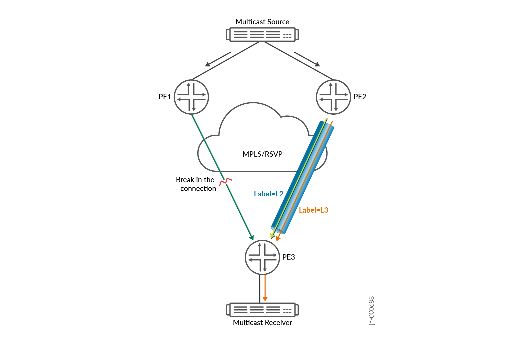
In the figure below, PE3 is configured with MVPN Hot Root Standby (HRS) thereby fetching multicast traffic from both primary ingress device PE1 and secondary ingress device PE2. An RSVP P2MP tunnel is established between PE1 and PE3, with the incoming label L1. A second RSVP P2MP tunnel exists between PE2 and PE3, with the incoming label L2. If PE1 is unreachable for any reason, the egress device PE3 starts fetching traffic from PE2. In the case an MBB event is triggered, PE2 signals for a new LSP path and PE3 allocates a new incoming LSP label L3. During this time, the RPF list in PE3 is programmed with two incoming labels. The ingress PE decides when to switch traffic from the old label to the new one. When the traffic switches to the new label, the old label is torn down. PE3 modifies its RPF NH to label L3, following which the traffic flow is restored.
With the grouping of both labels, L2 and L3 under one Session Id, switching
between the two LSP labels becomes seamless and causes a minimal transition delay of sub-50
ms.
Similarly, for MVPN provider tunnels with a threshold for I-PMSI traffic rate, the traffic flows through the I-PMSI tunnel until the threshold is exceeded, in which case the traffic switches to the S-PMSI tunnel. During this switchover from the I-PMSI to S-PMSI tunnel, you may experience traffic loss due to a change in the next-hop from which the egress PE was receiving and forwarding traffic.
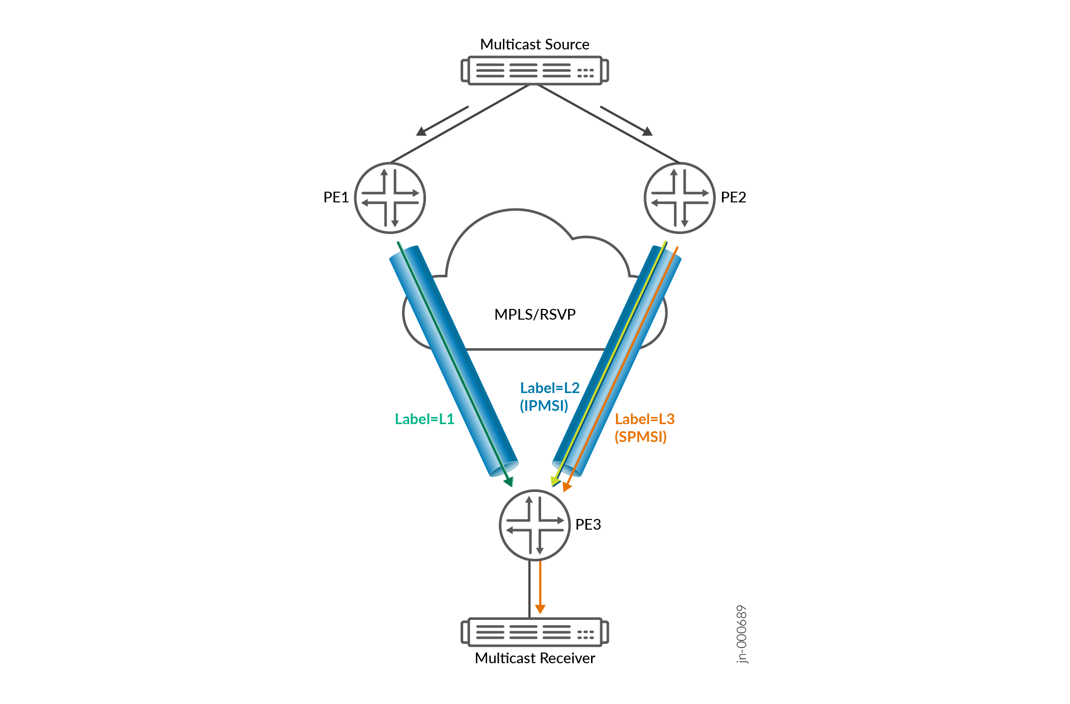
Junos uses the Session Id to group I-PMSI and S-PMSI next-hops together,
minimizing the transition delay to sub-50 ms.
Running the command show multicast route extensive instance
instance will include the Session Id and
Session Status if present.
user@router> show multicast route extensive instance instance1

Instance: vrf4 Family: INET
Group: 233.252.0.1
    Source: 172.16.0.1/32
    Upstream rpf interface list:
        vt-5/0/0.0 (P)
            Session Id: 0x38a7 Session Status: Up
            Min-rate: 3000 kbps Weight: 1
            Sender Id: Label 24
        vt-5/0/0.0 (B)
            Session Id: 0x38a8 Session Status: Up
    Min-rate: 3000 kbps Weight: 65533
            Sender Id: Label 23
    Downstream interface list:
        et-5/1/5.0
    Number of outgoing interfaces: 1
    Session description: NOB Cross media facilities
    Statistics: 349 kBps, 1465 pps, 1552316 packets
    RPF Next-hop ID: 5326
    Next-hop ID: 1048585
    Upstream protocol: MVPN
    Route state: Active
    Forwarding state: Forwarding
    Cache lifetime/timeout: forever