ON THIS PAGE
Example: Configuring Next-Hop-Based MPLS-Over-UDP Dynamic Tunnels
Anti-Spoofing Protection for Next-Hop-Based Dynamic Tunnels Overview
Example: Configuring Anti-Spoofing Protection for Next-Hop-Based Dynamic Tunnels
Overview of Next-Hop-Based Dynamic Tunneling Using IP-Over-IP Encapsulation
Example: Configuring Next-Hop-Based IP-Over-IP Dynamic Tunnels
Next-Hop-Based Dynamic Tunnels
Example: Configuring Next-Hop-Based MPLS-Over-UDP Dynamic Tunnels
This example shows how to configure a dynamic MPLS-over-UDP tunnel that includes a tunnel composite next hop. The MPLS-over-UDP feature provides a scaling advantage on the number of IP tunnels supported on a device.
Starting in Junos OS Release 18.3R1,
MPLS-over-UDP tunnels are supported on PTX Series routers and QFX Series switches. For
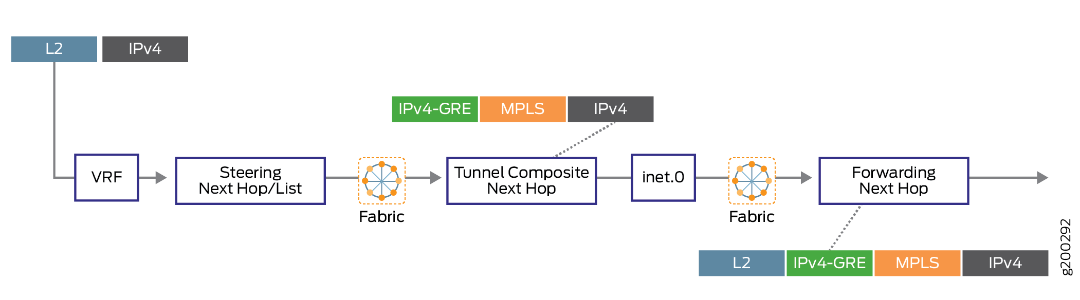
every dynamic tunnel configured on a PTX router or a QFX switch, a tunnel composite next
hop, an indirect next hop, and a forwarding next hop is created to resolve the tunnel
destination route. You can also use policy control to resolve the dynamic tunnel over
select prefixes by including the forwarding-rib configuration statement at the [edit routing-options
dynamic-tunnels] hierarchy level.
Requirements
This example uses the following hardware and software components:
-
Five MX Series routers with MPCs and MICs.
-
Junos OS Release 16.2 or later running on the provider edge (PE) routers.
Before you begin:
-
Configure the device interfaces, including the loopback interface.
-
Configure the router ID and autonmous system number for the device.
-
Establish an internal BGP (IBGP) session with the remote PE device.
-
Establish OSPF peering among the devices.
Overview
Starting with Junos OS Release 16.2, a dynamic UDP tunnel supports the creation of a tunnel composite next hop for every UDP tunnel configured. These next-hop-based dynamic UDP tunnels are referred to as MPLS-over-UDP tunnels. The tunnel composite next hop are enabled by default for the MPLS-over-UDP tunnels.
MPLS-over-UDP tunnels can be bidirectional or unidirectional in nature.
-
Bidirectional—When the PE devices are connected over MPLS-over-UDP tunnels in both directions, it is called a bidirectional MPLS-over-UDP tunnel.
-
Unidirectional—When two PE devices are connected over MPLS-over-UDP tunnel in one direction, and over MPLS/IGP in the other direction, it is called an unidirectional MPLS-over-UDP tunnel.
Unidirectional MPLS-over-UDP tunnels are used in migration scenarios, or in cases where two PE devices provide connectivity to each other over two disjoint networks. Because reverse direction tunnel does not exist for unidirectional MPLS-over-UDP tunnels, you must configure a filter-based MPLS-over-UDP decapsulation on the remote PE device for forwarding the traffic.
Starting in Junos OS Release 18.2R1, on PTX series routers and QFX10000 with unidirectional MPLS-over-UDP tunnels, you must configure the remote PE device with an input filter for MPLS-over-UDP packets, and an action for decapsulating the IP and UDP headers for forwarding the packets in the reverse tunnel direction.
For example, on the remote PE device, Device PE2, the following configuration is required for unidirectional MPLS-over-UDP tunnels:
PE2
[edit firewall filter] user@host# set Decap_Filter term udp_decap from protocol udp user@host# set Decap_Filter term udp_decap from destination-port 6635 user@host# set Decap_Filter term udp_decap then count UDP_PKTS user@host# set Decap_Filter term udp_decap then decapsulate mpls-in-udp user@host# set Decap_Filter term def then count def_pkt user@host# set Decap_Filter term def then accept
In the above sample configuration, Decap_Filter is the name of the firewall filter used for MPLS-over-UDP decapsulation. The term udp_decap is the input filter for accepting UDP packets on the core-facing interface of Device PE2, and then decapsulate the MPLS-over-UDP packets to MPLS-over-IP packets for forwarding.
You can use the existing firewall operational mode commands, such as show
firewall filter to view the filter-based MPLS-over-UDP
decapsulation.
For example:
user@host >show firewall filter Decap_Filter Filter: Decap_Filter Counters: Name Bytes Packets UDP_PKTS 16744 149 def_pkt 13049 136
For unidirectional MPLS-over-UDP tunnels:
-
Only IPv4 address is supported as the outer header. Filter-based MPLS-over-UDP decapsulation does not support IPv6 address in the outer header.
-
Only the default routing instance is supported after decapsulation.
Starting in Junos OS Release 17.1, on MX Series routers with MPCs and MICs, the scaling limit of MPLS-over-UDP tunnels is increased.
Starting in Junos Release 19.2R1, on MX Series routers with MPCs and MICs, carrier supporting carrier (CSC) architecture can be deployed with MPLS-over-UDP tunnels carrying MPLS traffic over dynamic IPv4 UDP tunnels that are established between supporting carrier's PE devices. With this enhancement, the scaling advantage that the MPLS-over-UDP tunnels provided is further increased. The CSC support with MPLS-over-UDP tunnel is not supported for IPv6 UDP tunnel.
The existing dynamic tunnel feature requires complete static configuration. Currently, the tunnel information received from peer devices in advertised routes is ignored. Starting in Junos OS Release 17.4R1, on MX Series routers, the next-hop-based dynamic MPLS-over-UDP tunnels are signaled using BGP encapsulation extended community. BGP export policy is used to specify the tunnel types, advertise the sender side tunnel information, and parse and convey the receiver side tunnel information. A tunnel is created according to the received type tunnel community.
Multiple tunnel encapsulations are supported by BGP. On receiving multiple capability, the next-hop-based dynamic tunnel is created based on the configured BGP policy and tunnel preference. The tunnel preference should be consistent across both the tunnel ends for the tunnel to be set up. By default, MPLS-over-UDP tunnel is preferred over GRE tunnels. If dynamic tunnel configuration exists, it takes precedence over received tunnel community.
When configuring a next-hop-based dynamic MPLS-over-UDP tunnel, be aware of the following considerations:
-
An IBGP session must be configured between the PE devices.
-
A switchover between the next-hop-based dynamic tunnel encapsulations (UDP and GRE) is allowed, and this can impact network performance in terms of the supported IP tunnel scaling values in each mode.
-
Having both GRE and UDP next-hop-based dynamic tunnel encapsulation types for the same tunnel destination leads to a commit failure.
-
For unidirectional MPLS-over-UDP tunnels, you must explicitly configure filter-based MPLS-over-UDP decapsulation on the remote PE device for the packets to be forwarded.
-
Graceful Routing Engine switchover (GRES) is supported with MPLS-over-UDP, and the MPLS-over-UDP tunnel type flags are unified ISSU and NSR compliant.
-
MPLS-over-UDP tunnels are supported on virtual MX (vMX) in Lite mode.
-
MPLS-over-UDP tunnels support dynamic GRE tunnel creation based upon new IPv4-mapped-IPv6 next hops.
-
MPLS-over-UDP tunnel are supported in interoperability with contrail, wherein the MPLS-over-UDP tunnels are created from the contrail vRouter to an MX gateway. To enable this, the following community is required to be advertised in the route from the MX Series router to the contrail vRouter:
[edit policy-options community] udp members 0x030c:64512:13;
At a given point in time, only one tunnel type is supported on the contrail vRouter—next-hop-based dynamic GRE tunnels, MPLS-over-UDP tunnels, or VXLAN.
-
The following features are not supported with the next-hop-based dynamic MPLS-over-UDP tunnel configuration:
-
RSVP automatic mesh
-
Plain IPV6 GRE and UDP tunnel configuration
-
Logical systems
-
Topology
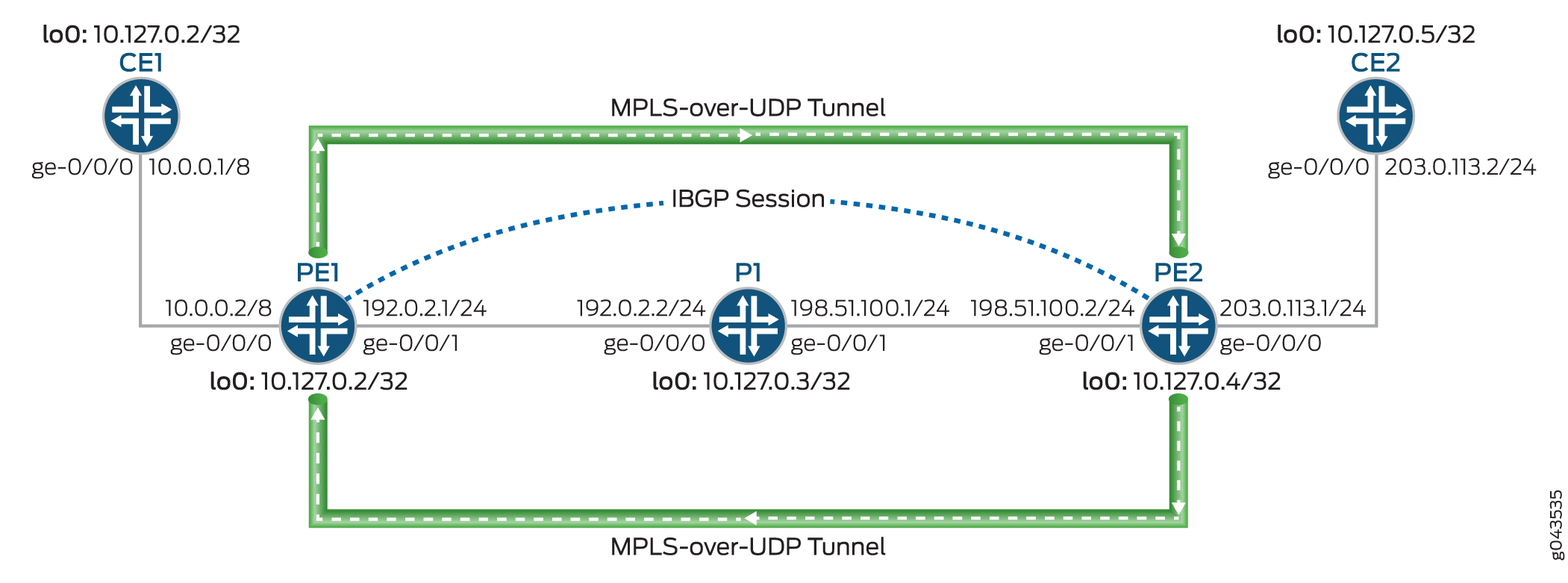
Figure 1 illustrates a Layer 3 VPN scenario over dynamic MPLS-over-UDP tunnels. The customer edge (CE) devices, CE1 and CE2, connect to provider edge (PE) devices, PE1 and PE2, respectively. The PE devices are connected to a provider device (Device P1), and an internal BGP (IBGP) session interconnects the two PE devices. A dynamic next-hop-based bidirectional MPL-over-UDP tunnel is configured between the PE devices.
The MPLS-over-UDP tunnel is handled as follows:
-
After a MPLS-over-UDP tunnel is configured, a tunnel destination mask route with a tunnel composite next hop is created for the tunnel in the inet.3 routing table. This IP tunnel route is withdrawn only when the dynamic tunnel configuration is deleted.
The tunnel composite next-hop attributes include the following:
-
When Layer 3 VPN composite next hop is disabled—Source and destination address, encapsulation string, and VPN label.
-
When Layer 3 VPN composite next hop and per-prefix VPN label allocation are enabled—Source address, destination address, and encapsulation string.
-
When Layer 3 VPN composite next hop is enabled and per-prefix VPN label allocation is disabled—Source address, destination address, and encapsulation string. The route in this case is added to the other virtual routing and forwarding instance table with a secondary route.
-
-
The PE devices are interconnected using an IBGP session. The IBGP route next hop to a remote BGP neighbor is the protocol next hop, which is resolved using the tunnel mask route with the tunnel next hop.
-
After the protocol next hop is resolved over the tunnel composite next hop, indirect next hops with forwarding next hops are created.
-
The tunnel composite next hop is used to forward the next hops of the indirect next hops.
Configuration
CLI Quick Configuration
To quickly configure this example, copy the following commands, paste them into a
text file, remove any line breaks, change any details necessary to match your
network configuration, copy and paste the commands into the CLI at the
[edit] hierarchy level, and then enter
commit from configuration mode.
CE1
set interfaces ge-0/0/0 unit 0 family inet address 10.0.0.1/8 set interfaces lo0 unit 0 family inet address 10.127.0.1/32 set routing-options router-id 10.127.0.1 set routing-options autonomous-system 65200 set protocols bgp group ce1-pe1 export export-loopback-direct set protocols bgp group ce1-pe1 peer-as 100 set protocols bgp group ce1-pe1 neighbor 10.0.0.2 set policy-options policy-statement export-loopback-direct term term-1 from interface lo0.0 set policy-options policy-statement export-loopback-direct term term-1 from route-filter 10.127.0.1/32 exact set policy-options policy-statement export-loopback-direct term term-1 then accept
CE2
set interfaces ge-0/0/0 unit 0 family inet address 203.0.113.2/24 set interfaces lo0 unit 0 family inet address 10.127.0.5/32 set routing-options router-id 10.127.0.5 set routing-options autonomous-system 65200 set protocols bgp group ce1-pe1 export export-loopback-direct set protocols bgp group ce1-pe1 peer-as 65100 set protocols bgp group ce1-pe1 neighbor 203.0.113.1 set policy-options policy-statement export-loopback-direct term term-1 from interface lo0.0 set policy-options policy-statement export-loopback-direct term term-1 from route-filter 10.127.0.5/32 exact set policy-options policy-statement export-loopback-direct term term-1 then accept
PE1
set interfaces ge-0/0/0 unit 0 family inet address 10.0.0.2/8 set interfaces ge-0/0/1 unit 0 family inet address 192.0.2.1/24 set interfaces ge-0/0/1 unit 0 family mpls set interfaces lo0 unit 0 family inet address 10.127.0.2/32 set routing-options static route 10.33.0/16 next-hop 192.0.2.2 set routing-options router-id 10.127.0.2 set routing-options autonomous-system 65100 set routing-options forwarding-table export pplb set routing-options dynamic-tunnels gre next-hop-based-tunnel set routing-options dynamic-tunnels udp-dyn-tunnel-to-pe2 source-address 10.127.0.2 set routing-options dynamic-tunnels udp-dyn-tunnel-to-pe2 udp set routing-options dynamic-tunnels udp-dyn-tunnel-to-pe2 destination-networks 10.127.0.0/24 set protocols bgp group IBGP type internal set protocols bgp group IBGP local-address 10.127.0.2 set protocols bgp group IBGP family inet-vpn unicast set protocols bgp group IBGP neighbor 10.127.0.4 set protocols ospf area 0.0.0.0 interface ge-0/0/1.0 set protocols ospf area 0.0.0.0 interface lo0.0 passive set routing-instances MPLS-over-UDP-PE1 instance-type vrf set routing-instances MPLS-over-UDP-PE1 interface ge-0/0/0.0 set routing-instances MPLS-over-UDP-PE1 route-distinguisher 10.127.0.2:1 set routing-instances MPLS-over-UDP-PE1 vrf-target target:600:1 set routing-instances MPLS-over-UDP-PE1 protocols bgp group pe1-ce1 peer-as 65200 set routing-instances MPLS-over-UDP-PE1 protocols bgp group pe1-ce1 neighbor 10.0.0.1 as-override
P1
set interfaces ge-0/0/0 unit 0 family inet address 192.0.2.2/24 set interfaces ge-0/0/0 unit 0 family mpls set interfaces ge-0/0/1 unit 0 family inet address 198.51.100.1/24 set interfaces ge-0/0/1 unit 0 family mpls set interfaces lo0 unit 0 family inet address 10.127.0.3/32 set routing-options router-id 10.127.0.3 set routing-options autonomous-system 65100 set protocols ospf area 0.0.0.0 interface ge-0/0/0.0 set protocols ospf area 0.0.0.0 interface ge-0/0/1.0 set protocols ospf area 0.0.0.0 interface lo0.0 passive
PE2
set interfaces ge-0/0/0 unit 0 family inet address 203.0.113.1/24 set interfaces ge-0/0/1 unit 0 family inet address 198.51.100.2/24 set interfaces ge-0/0/1 unit 0 family mpls set interfaces lo0 unit 0 family inet address 10.127.0.4/8 set routing-options nonstop-routing set routing-options router-id 10.127.0.4 set routing-options autonomous-system 65100 set routing-options forwarding-table export pplb set routing-options dynamic-tunnels udp-dyn-tunnel-to-pe1 source-address 10.127.0.4 set routing-options dynamic-tunnels udp-dyn-tunnel-to-pe1 udp set routing-options dynamic-tunnels udp-dyn-tunnel-to-pe1 destination-networks 10.127.0.0/24 set protocols bgp group IBGP type internal set protocols bgp group IBGP local-address 10.127.0.4 set protocols bgp group IBGP family inet-vpn unicast set protocols bgp group IBGP neighbor 10.127.0.2 set protocols ospf area 0.0.0.0 interface ge-0/0/1.0 set protocols ospf area 0.0.0.0 interface lo0.0 passive set routing-instances MPLS-over-UDP-PE2 instance-type vrf set routing-instances MPLS-over-UDP-PE2 interface ge-0/0/0.0 set routing-instances MPLS-over-UDP-PE2 route-distinguisher 10.127.0.4:1 set routing-instances MPLS-over-UDP-PE2 vrf-target target:600:1 set routing-instances MPLS-over-UDP-PE2 protocols bgp group ebgp peer-as 65200 set routing-instances MPLS-over-UDP-PE2 protocols bgp group ebgp neighbor 203.0.113.2 as-override
Procedure
Step-by-Step Procedure
The following example requires that you navigate various levels in the configuration hierarchy. For information about navigating the CLI, see Using the CLI Editor in Configuration Mode in the CLI User Guide.
To configure Device PE1:
-
Configure the device interfaces including the loopback interface of the device.
[edit interfaces] user@PE1# set ge-0/0/0 unit 0 family inet address 10.0.0.2/8 user@PE1# set ge-0/0/1 unit 0 family inet address 192.0.2.1/24 user@PE1# set ge-0/0/1 unit 0 family mpls user@PE1# set lo0 unit 0 family inet address 10.127.0.2/8
-
Configure a static route for routes from Device PE1 with Device P1 as the next-hop destination.
[edit routing-options] user@PE1# set static route 10.33.0.0/16 next-hop 192.0.2.2
-
Configure the router-ID and autonomous system number for Device PE1.
[edit routing-options] user@PE1# set router-id 10.127.0.2 user@PE1# set autonomous-system 65100
-
(PTX Series only) Configure policy control to resolve the MPLS-over-UDP dynamic tunnel route over select prefixes.
[edit routing-options dynamic-tunnels] user@PTX-PE1# set forwarding-rib inet.0 inet-import dynamic-tunnel-fwd-route-import
-
(PTX Series only) Configure the inet-import policy for resolving dynamic tunnel destination routes over .
[edit policy-options]
user@PTX-PE1# set policy-statement dynamic-tunnel-fwd-route-import term 1 from route-filter 10.127.0.4/32 exact
user@PTX-PE1# set policy-statement dynamic-tunnel-fwd-route-import term 1 then accept
user@PTX-PE1# set policy-options policy-statement dynamic-tunnel-fwd-route-import then reject
-
Configure IBGP peering between the PE devices.
[edit protocols]
user@PE1# set bgp group IBGP type internal
user@PE1# set bgp group IBGP local-address 10.127.0.2
user@PE1# set bgp group IBGP family inet-vpn unicast
user@PE1# set bgp group IBGP neighbor 10.127.0.4
-
Configure OSPF on all the interfaces of Device PE1, excluding the management interface.
[edit protocols]
user@PE1# set ospf area 0.0.0.0 interface ge-0/0/1.0
user@PE1# set ospf area 0.0.0.0 interface lo0.0 passive
-
Enable next-hop-based dynamic GRE tunnel configuration on Device PE1.
Note:This step is required only for illustrating the implementation difference between next-hop-based dynamic GRE tunnels and MPLS-over-UDP tunnels.
[edit routing-options]
user@PE1# set dynamic-tunnels gre next-hop-based-tunnel
-
Configure the MPLS-over-UDP tunnel parameters from Device PE1 to Device PE2.
[edit routing-options]
user@PE1# set dynamic-tunnels udp-dyn-tunnel-to-pe2 source-address 10.127.0.2
user@PE1# set dynamic-tunnels udp-dyn-tunnel-to-pe2 udp
user@PE1# set dynamic-tunnels udp-dyn-tunnel-to-pe2 destination-networks 10.127.0.0/24
-
Configure a VRF routing instance on Device PE1 and other routing instance parameters.
[edit routing-instances]
user@PE1# set MPLS-over-UDP-PE1 instance-type vrf
user@PE1# set MPLS-over-UDP-PE1 interface ge-0/0/0.0
user@PE1# set MPLS-over-UDP-PE1 route-distinguisher 10.127.0.2:1
user@PE1# set MPLS-over-UDP-PE1 vrf-target target:600:1
-
Enable BGP in the routing instance configuration for peering with Device CE1.
[edit routing-instances]
user@PE1# set MPLS-over-UDP-PE1 protocols bgp group pe1-ce1 peer-as 65200
user@PE1# set MPLS-over-UDP-PE1 protocols bgp group pe1-ce1 neighbor 10.0.0.1 as-override
Results
From configuration mode, confirm your configuration by entering the show
interfaces, show routing-options, show
protocols, and show routing-instances commands. If
the output does not display the intended configuration, repeat the instructions
in this example to correct the configuration.
user@PE1# show interfaces
ge-0/0/0 {
unit 0 {
family inet {
address 10.0.0.2/8;
}
}
}
ge-0/0/1 {
unit 0 {
family inet {
address 192.0.2.1/24;
}
family mpls;
}
}
lo0 {
unit 0 {
family inet {
address 10.127.0.2/32;
}
}
}
user@PE1# show routing-options
static {
route 10.33.0.0/16 next-hop 192.0.2.2;
}
router-id 10.127.0.2;
autonomous-system 65100;
forwarding-table {
export pplb;
}
dynamic-tunnels {
gre next-hop-based-tunnel;
udp-dyn-tunnel-to-pe2 {
source-address 10.127.0.2;
udp;
destination-networks {
10.127.0.0/24;
}
}
}
user@PE1# show protocols
bgp {
group IBGP {
type internal;
local-address 10.127.0.2;
family inet-vpn {
unicast;
}
neighbor 10.127.0.4;
}
}
ospf {
area 0.0.0.0 {
interface ge-0/0/1.0;
interface lo0.0 {
passive;
}
}
}
user@PE1# show routing-instances
MPLS-over-UDP-PE1 {
instance-type vrf;
interface ge-0/0/0.0;
route-distinguisher 10.127.0.2:1;
vrf-target target:600:1;
protocols {
bgp {
group pe1-ce1 {
peer-as 65200;
neighbor 10.0.0.1 {
as-override;
}
}
}
}
}
If you are done configuring the device, enter commit from
configuration mode.
Verification
Confirm that the configuration is working properly.
- Verifying the Connection Between PE Devices
- Verify the Dynamic Tunnel Routes on Device PE1
- Verify the Dynamic Tunnel Routes on Device PE2
- Verifying That the Routes Have the Expected Indirect-Next-Hop Flag
Verifying the Connection Between PE Devices
Purpose
Verify the BGP peering status between Device PE1 and Device PE2, and the BGP routes received from Device PE2.
Action
From operational mode, run the show bgp summary and show route receive-protocol bgp ip-address table bgp.l3vpn.0 commands.
user@PE1> show bgp summary
Groups: 2 Peers: 2 Down peers: 0
Table Tot Paths Act Paths Suppressed History Damp State Pending
bgp.l3vpn.0
2 2 0 0 0 0
Peer AS InPkt OutPkt OutQ Flaps Last Up/Dwn State|#Active/Received/Accepted/Damped...
10.127.0.4 65100 139 136 0 0 58:23 Establ
bgp.l3vpn.0: 2/2/2/0
MPLS-over-UDP-PE1.inet.0: 2/2/2/0
10.10.0.1 65200 135 136 0 0 58:53 Establ
MPLS-over-UDP-PE1.inet.0: 1/1/1/0user@PE1> show route receive-protocol bgp 10.127.0.4 table bgp.l3vpn.0 bgp.l3vpn.0: 2 destinations, 2 routes (2 active, 0 holddown, 0 hidden) Prefix Nexthop MED Lclpref AS path 10.127.0.4:1:127.0.0.5/8 * 10.127.0.4 65100 65200 I
Meaning
-
In the first output, the BGP session state is
Establ, which means that the session is up and the PE devices are peered. -
In the second output, Device PE1 has learned a BGP route from Device PE2.
Verify the Dynamic Tunnel Routes on Device PE1
Purpose
Verify the routes in the inet.3 routing table and the dynamic tunnel database information on Device PE1.
Action
From operational mode, run the show route table inet.3, show dynamic-tunnels database terse, show dynamic-tunnels database, and show dynamic-tunnels database summary commands.
user@PE1> show route table inet.3
inet.3: 2 destinations, 2 routes (2 active, 0 holddown, 0 hidden)
+ = Active Route, - = Last Active, * = Both
10.127.0.0/24 *[Tunnel/300] 00:21:18
Tunnel
127.0.0.4/8 *[Tunnel/300] 00:21:18
Tunnel Compositeuser@PE1> show dynamic-tunnels database terse Table: inet.3 Destination-network: 10.127.0.0/24 Destination Source Next-hop Type Status 10.127.0.4/8 10.127.0.2 0xb395b10 nhid 613 udp Up
user@PE1> show dynamic-tunnels database
Table: inet.3
. . .
Tunnel to: 10.127.0.4/32
Reference count: 2
Next-hop type: UDP
Source address: 10.127.0.2 Tunnel Id: 2
Next hop: tunnel-composite, 0xb395b10, nhid 613
VPN Label: Push 299776 Reference count: 3
Traffic Statistics: Packets 0, Bytes 0
State: Upuser@PE1> show dynamic-tunnels database summary Dynamic Tunnels, Total 1 displayed GRE Tunnel: Active Tunnel Mode, Next Hop Base IFL Based, Total 0 displayed, Up 0, Down 0 Nexthop Based, Total 0 displayed, Up 0, Down 0 RSVP Tunnel: Total 0 displayed UDP Tunnel: Total 1 displayed, Up 1, Down 0
Meaning
-
In the first output, because Device PE1 is configured with the MPLS-over-UDP tunnel, a tunnel composite route is created for the inet.3 routing table route entry.
-
In the remaining outputs, the MPLS-over-UDP tunnel is displayed with the tunnel encapsulation type, tunnel next hop parameters, and tunnel status.
Verify the Dynamic Tunnel Routes on Device PE2
Purpose
Verify the routes in the inet.3 routing table and the dynamic tunnel database information on Device PE2.
Action
From operational mode, run the show route table inet.3, and the show dynamic-tunnels database terse commands.
user@PE2> show route table inet.3
inet.3: 2 destinations, 2 routes (2 active, 0 holddown, 0 hidden)
+ = Active Route, - = Last Active, * = Both
10.127.0.0/24 *[Tunnel/300] 00:39:31
Tunnel
10.127.0.2/32 *[Tunnel/300] 00:24:53
Tunnel Compositeuser@PE1> show dynamic-tunnels database terse Table: inet.3 Destination-network: 127.0.0.0/8 Destination Source Next-hop Type Status 10.127.0.2/32 10.127.0.4 0xb395450 nhid 615 udp Up
Meaning
The outputs show the MPLS-over-UDP tunnel creation and the next-hop ID assigned as the next-hop interface, similar to Device PE1.
Verifying That the Routes Have the Expected Indirect-Next-Hop Flag
Purpose
Verify that Device PE1 and Device PE2 are configured to maintain the indirect next hop to forwarding next-hop binding on the Packet Forwarding Engine forwarding table.
Action
From operational mode, run the show krt indirect-next-hop command on Device PE1 and Device PE2.
user@PE1> show krt indirect-next-hop
Indirect Nexthop:
Index: 1048574 Protocol next-hop address: 10.127.0.4
RIB Table: bgp.l3vpn.0
Label: Push 299776
Policy Version: 1 References: 1
Locks: 3 0xb2ab630
Flags: 0x0
INH Session ID: 0x0
INH Version ID: 0
Ref RIB Table: unknown
Tunnel type: UDP, Reference count: 3, nhid: 613
Destination address: 10.127.0.4, Source address: 10.127.0.2
Tunnel id: 2, VPN Label: Push 299776, TTL action: prop-ttl
IGP FRR Interesting proto count : 1
Chain IGP FRR Node Num : 1
IGP Resolver node(hex) : 0xb3c70dc
IGP Route handle(hex) : 0xb1ae688 IGP rt_entry protocol : Tunnel
IGP Actual Route handle(hex) : 0x0 IGP Actual rt_entry protocol : Anyuser@PE2> show krt indirect-next-hop
Indirect Nexthop:
Index: 1048575 Protocol next-hop address: 10.127.0.2
RIB Table: bgp.l3vpn.0
Label: Push 299776
Policy Version: 1 References: 2
Locks: 3 0xb2ab740
Flags: 0x0
INH Session ID: 0x0
INH Version ID: 0
Ref RIB Table: unknown
Tunnel type: UDP, Reference count: 3, nhid: 615
Destination address: 10.127.0.2, Source address: 10.127.0.4
Tunnel id: 1, VPN Label: Push 299776, TTL action: prop-ttl
IGP FRR Interesting proto count : 2
Chain IGP FRR Node Num : 1
IGP Resolver node(hex) : 0xb3d3a28
IGP Route handle(hex) : 0xb1ae634 IGP rt_entry protocol : Tunnel
IGP Actual Route handle(hex) : 0x0 IGP Actual rt_entry protocol : AnyMeaning
The outputs show that a next-hop-based dynamic MPLS-over-UDP tunnel is created between the PE devices.
Troubleshooting
To troubleshoot the next-hop-based dynamic tunnels, see:
Troubleshooting Commands
Problem
The next-hop-based dynamic MPLS-over-UDP tunnel configuration is not taking effect.
Solution
To troubleshoot the next-hop-based MPLS-over-UDP tunnel configuration, use
the following traceroute commands at the [edit
routing-options dynamic-tunnels] statement hierarchy:
-
traceoptions file file-name -
traceoptions file size file-size -
traceoptions flag all
For example:
[edit routing-options dynamic-tunnels]
traceoptions {
file udp_dyn_pe1.wri size 4294967295;
flag all;
}
Anti-Spoofing Protection for Next-Hop-Based Dynamic Tunnels Overview
With the rise in deployment of high-scale IP tunnels in data centers, there is a need to add security measures that allow users to limit malicious traffic from compromised virtual machines (VMs). One possible attack is the injecting of traffic into an arbitrary customer VPN from a compromised server through the gateway router. In such cases, anti-spoofing checks on IP tunnels ensure that only legitimate sources are injecting traffic into data centers from their designated IP tunnels.
Next-hop-based dynamic IP tunnels create a tunnel composite next hop for every dynamic tunnel created on the device. Because next-hop-based dynamic tunnels remove the dependency on physical interfaces for every new dynamic tunnel configured, configuring next-hop-based dynamic tunnels provides a scaling advantage over the number of dynamic tunnels that can be created on a device. Starting in Junos OS Release 17.1, anti-spoofing capabilities for next-hop-based dynamic IP tunnels is provided for next-hop-based dynamic tunnels. With this enhancement, a security measure is implemented to prevent injecting of traffic into an arbitrary customer VPN from a compromised server through the gateway router.
Anti-spoofing is implemented using reverse path forwarding checks in the Packet Forwarding Engine. The checks are implemented for the traffic coming through the tunnel to the routing instance. Currently, when the gateway router receives traffic from a tunnel, only the destination lookup us done and the packet is forwarded accordingly. When anti-spoofing protection is enabled, the gateway router also does a source address lookup of the encapsulation packet IP header in the VPN, in addition to the tunnel destination lookup. This ensures that legitimate sources are injecting traffic through their designated IP tunnels. As a result, anti-spoofing protection ensures that the tunnel traffic is received from a legitimate source on the designated tunnels.
Figure 2 illustrates a sample topology with the requirements for anti-spoofing protection.
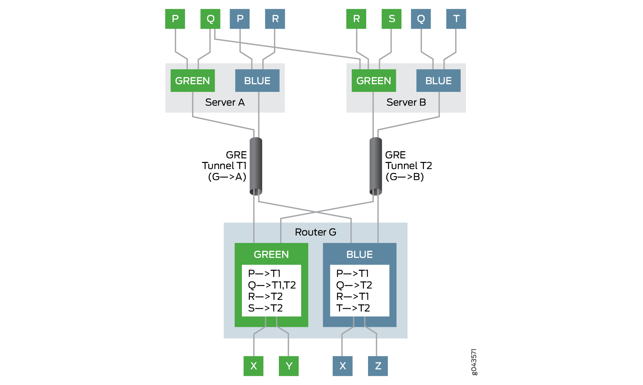
In this example, the gateway router is Router G. Router G has two VPNs—Green and Blue. The two servers, Server A and Server B, can reach the Green and Blue VPNs on Router G through the next-hop-based dynamic tunnels T1 and T2, respectively. Several hosts and virtual machines (P, Q, R, S, and T) connected to the servers can reach the VPNs through the gateway router, Router G. Router G has the virtual routing and forwarding (VRF) tables for Green and Blue VPNs, each populated with the reachability information for the virtual machines in those VPNs.
For example, in VPN Green, Router G uses tunnel T1 to reach host P, tunnel T2 to reach hosts R and S, and load balancing is done between tunnels T1 and T2 to reach the multihomed host Q. In VPN Blue, Router G uses tunnel T1 to reach hosts P and R, and tunnel T2 to reach hosts Q and T.
The check passes for reverse path forwarding when:
A packet comes from a legitimate source on its designated tunnel.
Host P in VPN Green sends a packet to host X using tunnel T1. Because Router G can reach host P through tunnel T1, it allows the packet to pass and forwards the packet to host X.
A packet comes from a multihomed source on its designated tunnels.
Host Q in VPN Green is multihomed on servers A and B, and can reach Router G through tunnels T1 and T2. Host Q sends a packet to host Y using tunnel T1, and a packet to host X using tunnel T2. Because Router G can reach host Q through tunnels T1 and T2, it allows the packets to pass and forwards them to hosts Y and X, respectively.
Layer 3 VPNs do not have anti-spoofing protection enabled by
default. To enable anti-spoofing for next-hop-based dynamic tunnels,
include the ip-tunnel-rpf-check statement at the [edit
routing-instances routing-instance-name routing-options
forwarding-table] hierarchy level. The reverse path forwarding
check is applied to the VRF routing instance only. The default mode
is set to strict, where the packet that comes from a source
on a nondesignated tunnel does not pass the check. The ip-tunnel-rpf-check mode can be set as loose, where the reverse path forwarding
check fails when the packet comes from a nonexistent source. An optional
firewall filter can be configured under the ip-tunnel-rpf-check statement to count and log the packets that failed the reverse path
forwarding check.
The following sample output shows an anti-spoofing configuration:
[edit routing-instances routing-instance-name routing-options forwarding-table]
ip-tunnel-rpf-check {
mode loose;
fail-filter filter-name;
}
Take the following guidelines under consideration when configuring anti-spoofing protection for next-hop-based dynamic tunnels:
Anti-spoofing protection can be enabled for IPv4 tunnels and IPv4 data traffic only. The anti-spoofing capabilities are not supported on IPv6 tunnels and IPv6 data traffic.
Anti-spoofing for next-hop-based dynamic tunnels can detect and prevent a compromised virtual machine (inner source reverse path forwarding check) but not a compromised server that is label-spoofing.
The next-hop-based IP tunnels can originate and terminate on an inet.0 routing table.
Anti-spoofing protection is effective when the VRF routing instance has label-switched interfaces (LSIs) (using the
vrf-table-label), or virtual tunnel (VT) interfaces. Withper-next-hoplabel on the VRF routing instance, anti-spoofing protection is not supported.The
rpf fail-filteris applicable only to the inner IP packet.Enabling anti-spoofing checks does not affect the scaling limit of the next-hop-based dynamic tunnels on a device.
The system resource utilization with anti-spoofing protection enabled for the VRF routing instance is slightly higher than the utilization of next-hop-based dynamic tunnels without the anti-spoofing protection enabled.
Anti-spoofing protection requires additional source IP address checks, which has minimal impact on network performance.
Graceful Routing Engine switchover (GRES) and in-service software upgrade (ISSU) are supported with anti-spoofing protection.
Example: Configuring Anti-Spoofing Protection for Next-Hop-Based Dynamic Tunnels
This example shows how to configure reverse path forwarding checks for the virtual routing and forwarding (VRF) routing instance to enable anti-spoofing protection for next-hop-based dynamic tunnels. The checks ensure that legitimate sources are injecting traffic through their designated IP tunnels.
Requirements
This example uses the following hardware and software components:
Three MX Series Routers with MICs, each connected to a host device.
Junos OS Release 17.1 or later running on one or all the routers.
Before you begin:
Enable tunnel services configuration on the Flexible PIC Concentrator.
Configure the router interfaces.
Configure the router-ID and assign an autonomous system number for the router.
Establish an internal BGP (IBGP) session with the tunnel endpoints.
Configure RSVP on all the routers.
Configure OSPF or any other interior gateway protocol on all the routers.
Configure two dynamic next-hop-based IP tunnels between the two routers.
Configure a VRF routing instance for every router-to-host connection.
Overview
Starting in Junos OS Release 17.1, anti-spoofing capabilities are added to next-hop-based dynamic IP tunnels, where checks are implemented for the traffic coming through the tunnel to the routing instance using reverse path forwarding in the Packet Forwarding Engine.
Currently, when the gateway router receives traffic from a tunnel, only the destination address lookup is done before forwarding. With anti-spoofing protection, the gateway router does a source address lookup of the encapsulation packet IP header in the VPN to ensure that legitimate sources are injecting traffic through their designated IP tunnels. This is called the strict mode and is the default behavior of anti-spoofing protection. To pass traffic from nondesignated tunnels, the reverse path forwarding check is enabled in the lose mode. For traffic received from nonexistent sources, the reverse path forwarding check fails for both the strict and loose modes.
Anti-spoofing is supported on VRF routing instances. To enable
anti-spoofing for dynamic tunnels, include the ip-tunnel-rpf-check statement at the [edit routing-instances routing-instance-name
routing-options forwarding-table] hierarchy level.
Topology
Figure 3 illustrates a sample network topology enabled with anti-spoofing protection. Routers R0, R1 and R2 are each connected to hosts Host0, Host1, and Host2, respectively. Two generic routing encapsulation (GRE) next-hop-based dynamic tunnels, Tunnel 1 and Tunnel 2 – connect Router R0 with Routers R1 and R2, respectively. The VRF routing instance is running between each router and its connected host devices.
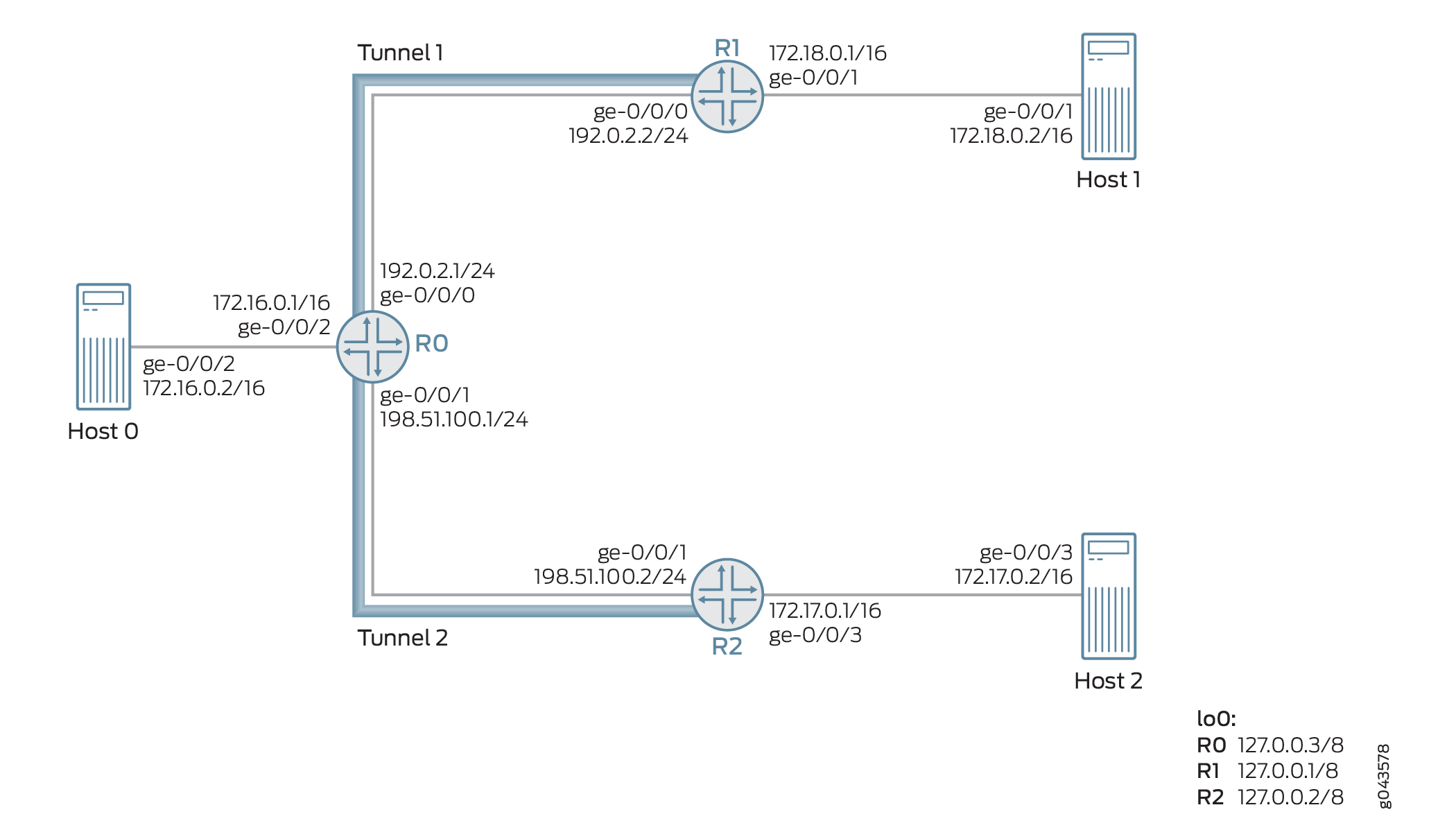
Taking as an example, three packets (Packets A, B, and C) are received on Router 0 from Router R2 through the next-hop-based dynamic GRE tunnel (Tunnel 2). The source IP address of these packets are 172.17.0.2 (Packet A), 172.18.0.2 (Packet B), and 172.20.0.2 (Packet C).
The source IP address of Packets A and B belong to Host 2 and Host 1, respectively. Packet C is a nonexistent source tunnel. The designated tunnel in this example is Tunnel 2, and the nondesignated tunnel is Tunnel 1. Therefore, the packets are processed as follows:
Packet A—Because the source is coming from a designated tunnel (Tunnel 2), Packet A passes the reverse path forwarding check and is processed for forwarding through Tunnel 2.
Packet B—Because the source is coming from Tunnel 1, which is a nondesinated tunnel, by default, Packet B fails the reverse path forwarding check in the strict mode. If loose mode is enabled, Packet B is allowed for forwarding.
Packet C—Because the source is a nonexistent tunnel source, Packet C fails the reverse path forwarding check, and the packet is not forwarded.
Configuration
CLI Quick Configuration
To quickly configure this example, copy the
following commands, paste them into a text file, remove any line breaks,
change any details necessary to match your network configuration,
copy and paste the commands into the CLI at the [edit] hierarchy
level, and then enter commit from configuration mode.
Router R0
set interfaces ge-0/0/0 unit 0 family inet address 192.0.2.1/24 set interfaces ge-0/0/1 unit 0 family inet address 198.51.100.1/24 set interfaces ge-0/0/2 vlan-tagging set interfaces ge-0/0/2 unit 0 vlan-id 1 set interfaces ge-0/0/2 unit 0 family inet address 172.16.0.1/16 set interfaces lo0 unit 0 family inet address 10.1.1.1/32 set routing-options router-id 10.1.1.1 set routing-options autonomous-system 100 set routing-options dynamic-tunnels gre next-hop-based-tunnel set routing-options dynamic-tunnels T1 source-address 192.0.2.1 set routing-options dynamic-tunnels T1 gre set routing-options dynamic-tunnels T1 destination-networks 192.0.2.0/24 set routing-options dynamic-tunnels T2 source-address 198.51.100.1 set routing-options dynamic-tunnels T2 gre set routing-options dynamic-tunnels T2 destination-networks 198.51.100.0/24 set protocols rsvp interface all set protocols rsvp interface fxp0.0 disable set protocols bgp group IBGP type internal set protocols bgp group IBGP local-address 10.1.1.1 set protocols bgp group IBGP family inet-vpn unicast set protocols bgp group IBGP neighbor 20.1.1.1 set protocols bgp group IBGP neighbor 30.1.1.1 set protocols ospf traffic-engineering set protocols ospf area 0.0.0.0 interface lo0.0 passive set protocols ospf area 0.0.0.0 interface all set routing-instances VPN1 instance-type vrf set routing-instances VPN1 interface ge-0/0/2.0 set routing-instances VPN1 route-distinguisher 100:100 set routing-instances VPN1 vrf-target target:100:1 set routing-instances VPN1 vrf-table-label set routing-instances VPN1 routing-options forwarding-table ip-tunnel-rpf-check mode strict set routing-instances VPN1 protocols bgp group External type external set routing-instances VPN1 protocols bgp group External family inet unicast set routing-instances VPN1 protocols bgp group External peer-as 200 set routing-instances VPN1 protocols bgp group External neighbor 172.16.0.1
Router R1
set interfaces ge-0/0/0 unit 0 family inet address 192.0.2.2/24 set interfaces ge-0/0/1 vlan-tagging set interfaces ge-0/0/1 unit 0 vlan-id 2 set interfaces ge-0/0/1 unit 0 family inet address 172.18.0.1/16 set interfaces lo0 unit 0 family inet address 20.1.1.1/32 set routing-options router-id 20.1.1.1 set routing-options autonomous-system 100 set routing-options dynamic-tunnels gre next-hop-based-tunnel set routing-options dynamic-tunnels T1 source-address 192.0.2.2 set routing-options dynamic-tunnels T1 gre set routing-options dynamic-tunnels T1 destination-networks 192.0.2.0/24 set protocols rsvp interface all set protocols rsvp interface fxp0.0 disable set protocols bgp group IBGP type internal set protocols bgp group IBGP local-address 20.1.1.1 set protocols bgp group IBGP family inet-vpn unicast set protocols bgp group IBGP neighbor 30.1.1.1 set protocols bgp group IBGP neighbor 10.1.1.1 set protocols ospf traffic-engineering set protocols ospf area 0.0.0.0 interface lo0.0 passive set protocols ospf area 0.0.0.0 interface all set routing-instances VPN2 instance-type vrf set routing-instances VPN2 interface ge-0/0/1.0 set routing-instances VPN2 route-distinguisher 100:200 set routing-instances VPN2 vrf-target target:200:1 set routing-instances VPN2 vrf-table-label
R2
set interfaces ge-0/0/1 unit 0 family inet address 198.51.100.2/24 set interfaces ge-0/0/2 vlan-tagging set interfaces ge-0/0/2 unit 0 vlan-id 3 set interfaces ge-0/0/2 unit 0 family inet address 172.17.0.1/16 set interfaces lo0 unit 0 family inet address 30.1.1.1/32 set routing-options router-id 30.1.1.1 set routing-options autonomous-system 100 set routing-options dynamic-tunnels gre next-hop-based-tunnel set routing-options dynamic-tunnels T2 source-address 198.51.100.2 set routing-options dynamic-tunnels T2 gre set routing-options dynamic-tunnels T2 destination-networks 198.51.100.0/24 set protocols rsvp interface all set protocols rsvp interface fxp0.0 disable set protocols bgp group IBGP type internal set protocols bgp group IBGP local-address 30.1.1.1 set protocols bgp group IBGP family inet-vpn unicast set protocols bgp group IBGP neighbor 20.1.1.1 set protocols bgp group IBGP neighbor 10.1.1.1 set protocols ospf traffic-engineering set protocols ospf area 0.0.0.0 interface lo0.0 passive set protocols ospf area 0.0.0.0 interface all set routing-instances VPN3 instance-type vrf set routing-instances VPN3 interface ge-0/0/2.0 set routing-instances VPN3 route-distinguisher 100:300 set routing-instances VPN3 vrf-target target:300:1 set routing-instances VPN3 vrf-table-label
Procedure
Step-by-Step Procedure
The following example requires that you navigate various levels in the configuration hierarchy. For information about navigating the CLI, see Using the CLI Editor in Configuration Mode in the CLI User Guide.
To configure Router R0:
Configure Router R0’s interfaces, including the loopback interface.
[edit interfaces] user@R0# set ge-0/0/0 unit 0 family inet address 192.0.2.1/24 user@R0# set ge-0/0/1 unit 0 family inet address 198.51.100.1/24 user@R0# set ge-0/0/2 vlan-tagging user@R0# set ge-0/0/2 unit 0 vlan-id 1 user@R0# set ge-0/0/2 unit 0 family inet address 172.16.0.1/16 user@R0# set lo0 unit 0 family inet address 10.1.1.1/32
Assign the router ID and autonomous system number for Router R0.
[edit routing-options] user@R0# set router-id 10.1.1.1 user@R0# set autonomous-system 100
Configure IBGP peering between the routers.
[edit protocols] user@R0# set bgp group IBGP type internal user@R0# set bgp group IBGP local-address 10.1.1.1 user@R0# set bgp group IBGP family inet-vpn unicast user@R0# set bgp group IBGP neighbor 20.1.1.1 user@R0# set bgp group IBGP neighbor 30.1.1.1
Configure OSPF on all the interfaces of Router R0, excluding the management interface.
[edit protocols] user@R0# set ospf traffic-engineering user@R0# set ospf area 0.0.0.0 interface lo0.0 passive user@R0# set ospf area 0.0.0.0 interface all
Configure RSVP on all the interfaces of Router R0, excluding the management interface.
[edit protocols] user@R0# set rsvp interface all user@R0# set rsvp interface fxp0.0 disable
Enable next-hop-based dynamic GRE tunnel configuration on Router R0.
[edit routing-options] user@R0# set dynamic-tunnels gre next-hop-based-tunnel
Configure the dynamic GRE tunnel parameters from Router R0 to Router R1.
[edit routing-options] user@R0# set dynamic-tunnels T1 source-address 192.0.2.1 user@R0# set dynamic-tunnels T1 gre user@R0# set dynamic-tunnels T1 destination-networks 192.0.2.0/24
Configure the dynamic GRE tunnel parameters from Router R0 to Router R2.
[edit routing-options] user@R0# set dynamic-tunnels T2 source-address 198.51.100.1 user@R0# set dynamic-tunnels T2 gre user@R0# set dynamic-tunnels T2 destination-networks 198.51.100.0/24
Configure a virtual routing and forwarding (VRF) routing instance on Router R0, and assign the interface connecting to Host 1 to the VRF instance.
[edit routing-instances] user@R0# set VPN1 instance-type vrf user@R0# set VPN1 route-distinguisher 100:100 user@R0# set VPN1 vrf-target target:100:1 user@R0# set VPN1 vrf-table-label user@R0# set VPN1 interface ge-0/0/2.0
Configure an external BGP session with Host 1 for the VRF routing instance.
[edit routing-instances] user@R0# set VPN1 protocols bgp group External type external user@R0# set VPN1 protocols bgp group External family inet unicast user@R0# set VPN1 protocols bgp group External peer-as 200 user@R0# set VPN1 protocols bgp group External neighbor 172.16.0.1
Configure anti-spoofing protection for the VRF routing instance on Router R0. This enables reverse path forwarding check for the next-hop-based dynamic tunnels, T1 and T2, on Router 0.
[edit routing-instances] user@R0# set VPN1 routing-options forwarding-table ip-tunnel-rpf-check mode strict
Results
From configuration mode, confirm your configuration
by entering the show interfaces, show routing-options, show protocols, and show routing-options commands.
If the output does not display the intended configuration, repeat
the instructions in this example to correct the configuration.
user@R0# show interfaces
ge-0/0/0 {
unit 0 {
family inet {
address 192.0.2.1/24;
}
}
}
ge-0/0/1 {
unit 0 {
family inet {
address 198.51.100.1/24;
}
}
}
ge-0/0/2 {
vlan-tagging;
unit 0 {
vlan-id 1;
family inet {
address 172.16.0.1/16;
}
}
}
lo0 {
unit 0 {
family inet {
address 10.1.1.1/32;
}
}
}
user@R0# show routing-options
router-id 10.1.1.1;
autonomous-system 100;
dynamic-tunnels {
gre next-hop-based-tunnel;
T1 {
source-address 192.0.2.1;
gre;
destination-networks {
192.0.2.0/24;
}
}
T2 {
source-address 198.51.100.1;
gre;
destination-networks {
198.51.100.0/24;
}
}
}
user@R0# show protocols
rsvp {
interface all;
interface fxp0.0 {
disable;
}
}
bgp {
group IBGP {
type internal;
local-address 10.1.1.1;
family inet-vpn {
unicast;
}
neighbor 20.1.1.1;
neighbor 30.1.1.1;
}
}
ospf {
traffic-engineering;
area 0.0.0.0 {
interface lo0.0 {
passive;
}
interface all;
}
}
user@R0# show routing-instances
VPN1 {
instance-type vrf;
interface ge-0/0/2.0;
route-distinguisher 100:100;
vrf-target target:100:1;
vrf-table-label;
routing-options {
forwarding-table {
ip-tunnel-rpf-check {
mode strict;
}
}
}
protocols {
bgp {
group External {
type external;
family inet {
unicast;
}
peer-as 200;
neighbor 172.16.0.1;
}
}
}
}
Verification
Confirm that the configuration is working properly.
- Verifying Basic Configuration
- Verifying Dynamic Tunnel Configuration
- Verifying Anti-Spoofing Protection Configuration
Verifying Basic Configuration
Purpose
Verify the OSPF and BGP peering status between the Router R0 and Routers R1 and R2.
Action
From operational mode, run the show ospf neighbor and show bgp summarycommands.
user@R0> show ospf neighbor
Address Interface State ID Pri Dead
192.0.2.2 ge-0/0/0.0 Full 20.1.1.1 128 32
198.51.100.2 ge-0/0/1.0 Full 30.1.1.1 128 32
user@R0> show bgp summary
Groups: 2 Peers: 3 Down peers: 1
Table Tot Paths Act Paths Suppressed History Damp State Pending
bgp.l3vpn.0
0 0 0 0 0 0
Peer AS InPkt OutPkt OutQ Flaps Last Up/Dwn State|#Active/Received/Accepted/Damped...
20.1.1.1 100 182 178 0 0 1:20:27 Establ
bgp.l3vpn.0: 0/0/0/0
30.1.1.1 100 230 225 0 0 1:41:51 Establ
bgp.l3vpn.0: 0/0/0/0
172.16.0.1 200 0 0 0 0 1:42:08 EstablMeaning
The OSPF and BGP sessions are up and running between the Routers R0, R1, and R2.
Verifying Dynamic Tunnel Configuration
Purpose
Verify the status of the next-hop-based dynamic GRE tunnels between the Router R0 and Routers R1 and R2.
Action
From operational mode, run the show route table inet.3, and the show dynamic-tunnels database terse commands.
user@R0> show route table inet.3
inet.3: 2 destinations, 2 routes (2 active, 0 holddown, 0 hidden)
+ = Active Route, - = Last Active, * = Both
192.0.2.0/24 *[Tunnel/300] 01:47:57
Tunnel
192.0.2.2/24 *[Tunnel/300] 01:47:57
Tunnel Composite
198.51.100.0/24 *[Tunnel/300] 01:47:57
Tunnel
198.51.100.2/24 *[Tunnel/300] 01:47:57
Tunnel Compositeuser@R0> show dynamic-tunnels database terse Table: inet.3 Destination-network: 192.0.2.0/24 Destination Source Next-hop Type Status 192.0.2.2/24 192.0.2.1 0xb395e70 nhid 612 gre Up Destination-network: 198.51.100.0/24 Destination Source Next-hop Type Status 198.51.100.2 198.51.100.1 0xb395e70 nhid 612 gre Up
Meaning
The two next-hop-based dynamic GRE tunnels, Tunnel 1 and Tunnel 2, are up.
Verifying Anti-Spoofing Protection Configuration
Purpose
Verify that the reverse path forwarding check has been enabled on the VRF routing instance on Router R0.
Action
From the operational mode, run the show krt table VPN1.inet.0 detail.
user@R0> show krt table VPN1.inet.0 detail
KRT tables:
VPN1.inet.0 : GF: 1 krt-index: 8 ID: 0 kernel-id: 8
flags: (null)
tunnel rpf config data : enable, strict, filter [0], 0x2
tunnel rpf tlv data : enable, strict, filter [0], 0x4
unicast reverse path: disabled
fast-reroute-priority: 0
Permanent NextHops
Multicast : 0 Broadcast : 0
Receive : 0 Discard : 0
Multicast Discard: 0 Reject : 0
Local : 0 Deny : 0
Table : 0Meaning
The configured reverse path forwarding check is enabled on the VRF routing instance in the strict mode.
Next-Hop-Based Dynamic Tunnel Localization Overview
Next-hop-based dynamic tunnels include generic routing encapsulation (GRE) tunnels and MPLS-over-UDP tunnels. These tunnels provide a scaling advantage over the interface-based tunnels. However, unlike the interface-based tunnels, the next-hop-based dynamic tunnels are anchorless in nature, where the forwarding information of the tunnels is distributed to the Packet Forwarding Engines (PFEs) on every line card on the device. This limits the maximum number of tunnels supported on the device to the tunnel capacity of a single line card. With the support for localization, you can configure next-hop-based dynamic tunnel localization to create the forwarding information only on the PFE of a line card that is designated as the anchor PFE. The PFEs on the other line cards on the device have state forwarding information to steer the packets to the anchor PFE. This provides a scaling advantage by increasing the maximum number of tunnels supported on a device.
- Benefits of Next-Hop-Based Dynamic Tunnel Localization
- Use Cases for Next-Hop-Based Dynamic Tunnel Localization
- Traffic Handling with Localization of Next-Hop-Based Dynamic Tunnels
- Configuring Next-Hop-Based Dynamic Tunnels Localization
- Troubleshooting Localized Next-Hop-Based Dynamic Tunnels
- Unsupported Features for Next-Hop-Based Dynamic Tunnels Localization
Benefits of Next-Hop-Based Dynamic Tunnel Localization
Provides a scaling advantage by increasing the maximum number of tunnels supported on a device.
Use Cases for Next-Hop-Based Dynamic Tunnel Localization
The IPsec gateway devices that host a number of MS-MPC are used to terminate IPSec tunnels and are required to support moderate load. This support is affected with the use of next-hop-based dynamic tunnels when the scaling limit of the device is reached. With the localization of next-hop-based dynamic tunnels, the maximum number of the tunnels supported is increased, allowing the device to accommodate more tunnels at the cost of an extra fabric hop.
For Internet or VPN gateway devices, such as a virtual public cloud data center, there is a need for the gateway devices to communicate with a large number of servers. The data center servers are reachable through next-hop-based dynamic tunnels. The anchorless property of the dynamic tunnels limits the overall scaling numbers of the device. The gateway devices host multiple MPCs, with increased traffic demands. With the localization of the next-hop-based dynamic tunnels, the tunnels can be spread across the MPCs, thereby facilitating an increase in the tunnel scaling numbers.
Traffic Handling with Localization of Next-Hop-Based Dynamic Tunnels
With support for localization, the next-hop-based dynamic tunnel state is localized to an anchor Packet Forwarding Engine, and the other Packet Forwarding Engine has the tunnel state for steering traffic to the tunnel anchor.
Figure 4 illustrates the forwarding path of next-hop-based dynamic tunnels without localization.
Figure 5 illustrates the forwarding path of next-hop-based dynamic tunnels with localization.
Configuring Next-Hop-Based Dynamic Tunnels Localization
Localization support can be configured for newly created next-hop-based dynamic tunnels, or for existing non-local dynamic tunnels.
- Configuring Localization for New Next-Hop-Based Dynamic Tunnels
- Configuring Localization for Existing Next-Hop-Based Dynamic Tunnels
Configuring Localization for New Next-Hop-Based Dynamic Tunnels
The localization of next-hop-based dynamic tunnels uses a policy-based approach to specify prefix groups. In other words, route policies are used to apply the localization properties to the next-hop-based dynamic tunnels. Dynamic tunnel attribute profiles are created and configured under routing options for association with the prefix group using the policy.
Creating dynamic tunnel profiles.
The dynamic tunnel profile specifies the tunnel type and the anchor Packet Forwarding Engine information. Multiple dynamic tunnel profiles can be created for localization of the dynamic tunnels. The values for the dynamic tunnel type can be GRE, UDP, or BGP-SIGNAL.
Although BGP-SIGNAL is not a valid tunnel type, on assigning BGP-SIGNAL as the tunnel type, the tunnels created from the BGP-signalled attributes are localized. When using BGP-SIGNAL, the tunnel type is decided based on the type advertised by BGP in its TLV. BGP-SIGNAL tunnels are always next-hop-based tunnels. The GRE tunnels created dynamically by BGP-SIGNAL are always next-hop-based, even if the user has manually configured tunnels created by GRE to use IFLs.
The anchor Packet Forwarding Engine value is the line card of the anchor Packet Forwarding Engine, for example, pfe-x/y/0. This information can be viewed from the
show interfaces terse pfe*command output.Sample Configuration:
[edit routing-options]
dynamic-tunnels {
    dynamic-tunnel-attributes attribute-1 {
        dynamic-tunnel-type <GRE | UDP | BGP-SIGNAL>;
        dynamic-tunnel-anchor-pfe pfe-1/0/0;
    }
}
Associating dynamic tunnel profile to prefix list.
Configuring a policy with
dynamic-tunnel-attributesas the action associates the dynamic tunnel to the prefix list. The policyfromaction allows the creation of tunnel with specified attributes for any matching condition, such as a prefix range, community, or source address of BGP routes, and so on.Sample configuration:
[edit policy-options]
policy-statement policy-name {
    term term {
        from {
            <route-filter | next-hop | community>>;
        }
        then {
            dynamic-tunnel-attributes <attribute-name>;
        }
    }
}
Including the tunnel policy under the forwarding table export policy.
After the policy is configured, it is included in the forwarding table export policy for the parsing of the policy.
Using the export-policy, the tunnel attributes get associated with the route. Whenever a route from BGP is queued for resolution, the forwarding table export policy is evaluated, and the tunnel attributes are obtained from the policy module based on the applied filters. The obtained tunnel attributes are then attached to the next hop in form of a tunnel composite next hop. The corresponding anchor forwarding structures, based on the Packet Forwarding Engine name and tunnel type, are created and sent to the forwarding table before a tunnel composite next hop is sent. However, if none of the attributes map to the tunnel composite next hop, then the forwarding structure is created on every Packet Forwarding Engine, similar to the non-localized dynamic tunnels.
Sample configuration:
[edit routing-options]
forwarding-table {
    export  dynamic-tunnel;
}
Configuring Localization for Existing Next-Hop-Based Dynamic Tunnels
Making on the fly changes to dynamic tunnel attributes can result in an FPC crash due to high memory utilization. Hence, we recommend deactivating the dynamic-tunnels configuration before configuring localization.
To update tunnel attributes for existing next-hop-based dynamic tunnels, the following should be performed:
Deactivate
dynamic-tunnelsconfiguration under the[edit routing-options]hierarchy level.Sample configuration:
[edit routing-options]
user@host# deactivate dynamic-tunnels
user@host# commit
Change tunnel attributes as required.
Activate
dynamic-tunnelsconfiguration under the[edit routing-options]hierarchy level.Sample configuration:
[edit routing-options]
user@host# activate dynamic-tunnels
user@host# commit
To configure localization for existing non-local next-hop-based dynamic tunnels:
Making on the fly changes to configure localization for existing non-local next-hop-based dynamic tunnels can result in an FPC crash due to high memory utilization. Hence, we recommend deactivating the dynamic-tunnels configuration before configuring localization.
Deactivate the
dynamic-tunnelsconfiguration at the[edit routing-options]hierarchy level.Create tunnel-attributes profile and add policy for localizing the dynamic tunnels, similar to new next-hop-based dynamic tunnels.
Activate the
dynamic-tunnelsconfiguration.
Troubleshooting Localized Next-Hop-Based Dynamic Tunnels
With localization of next-hop-based dynamic tunnels, the tunnel
composite next hops are associated with anchor Packet Forwarding Engine
IDs. The following traceroute configuration statements at the [edit routing-options] hierarchy level help in troubleshooting
the localized dynamic tunnels:
dynamic-tunnels traceoptions flag all—Tracking creation and deletion of tunnel in DTM.resolution traceoptions flag tunnel—Tracking resolver operations on BGP route.forwarding-table traceoptions flag all—Tracking tunnels sent to the kernel.traceoptions flag all—Tracking of route learning process.
The following commands can be used to check if a route is using a localized next-hop-based dynamic tunnel:
show route prefix extensive—To obtain the indirect next hop.
For example:
user@host> show route 1.2.3.4 extensive
MPLS-over-UDP-PE1.inet.0: 24 destinations, 26 routes (24 active, 0 holddown, 0 hidden)
1.2.3.4/32 (1 entry, 1 announced)
TSI:
KRT in-kernel 1.2.3.4/32 -> {indirect(1048577)}
Page 0 idx 1, (group pe1-ce1 type External) Type 1 val 0xb209a78 (adv_entry)
   Advertised metrics:
 	Nexthop: Self
 	AS path: [100] I
 	Communities: target:600:1 encapsulation:mpls-in-udp(0xd)
show krt indirect-next-hop index indirect-next-hop detail—To check for anchor Packet Forwarding Engine field in the detailed output of the indirect next hop.
For example:
user@host> show krt indirect-next-hop index 1048577 detail
Indirect Nexthop detail:
Index: 1048577 Protocol next-hop address: 1.1.1.6
  RIB Table: bgp.l3vpn.0            	Label: Push 299808
  Policy Version: 2                 	References: 11
  Locks: 3                          	0xb227980
  Flags: 0x0
  INH Session ID: 0x0
  Ref RIB Table: unknown
  Export policy detail:
 	(Dynamic tunnel hash : 309985522)
    	Tunnel type: UDP, Reference count: 4, nhid: 1016
    	Destination address: 1.1.1.6, Source address: 1.1.1.2
    	Anchored-PFE: pfe-1/0/0
    	VPN Label: Push 299808, TTL action: prop-ttl
  	IGP FRR Interesting proto count : 11
  	Chain IGP FRR Node Num      	: 1
     	IGP Resolver node(hex)   	: 0xc838b94
     	IGP Route handle(hex)    	: 0xb1d7674  	IGP rt_entry protocol    	: Tunnel
     	IGP Actual Route handle(hex) : 0x0        	IGP Actual rt_entry protocol : Any
Unsupported Features for Next-Hop-Based Dynamic Tunnels Localization
Junos OS does not support the following functionality with localization for next-hop-based dynamic tunnels:
Chained composite next hops at the
[edit routing-options
forwarding-table chained-composite-next-hop ingress l3vpn]
hierarchy level.Anchor Packet Forwarding Engine resiliency.
There is no resiliency support for next-hop-based dynamic tunnels with localization. After localization of the next-hop-based dynamic tunnels, the anchor Packer Forwarding Engine becomes the single entity for processing any given tunnel on the device. Although anchor Packer Forwarding Engine resiliency is not supported, for gateway devices, redundancy at the gateway device ensures that when the Packer Forwarding Engine to which the tunnel composite next hop is delegated goes down, the traffic must be rerouted to the redundant gateway device. The routing protocol process monitors the state of the Packer Forwarding Engine, and withdraws BGP advertisement of all the routes pointing to the tunnel composite next hops anchored on that Packer Forwarding Engine.
Only the anchored Packet Forwarding Engine has the full-fledged tunnel composite next hop and all the other Packet Forwarding Engines have only steering entries to forward traffic to the anchor Packet Forwarding Engine. These steering entries are not withdrawn, when an anchor FPC goes down.
Localization of next-hop-based dynamic tunnels is not supported on logical systems.
IPv6 is not supported with localization of next-hop-based dynamic tunnels.
With localization, the
show dynamic-tunnels database
summary
command does not display accurate tunnels summary when the state of the anchor Packet Forwarding Engine line card is not up. As a workaround, use theshow dynamic-tunnels databaseandshow dynamic-tunnels database tersecommand output.
Overview of Next-Hop-Based Dynamic Tunneling Using IP-Over-IP Encapsulation
Benefits
IP-over-IP tunneling provides the following benefits:
-
Alternative to MPLS over UDP—Can be used as an alternative to MPLS-over-UDP tunneling to provide IP service wherein there is a dedicated device per service.
-
Ability to steer specific traffic—Enables smooth migration when MPLS and IP networks co-exist because routes can be filtered to steer specific traffic over IP tunnels as opposed to MPLS tunnels.
-
Ability to support tunnels at increasing scale—Dynamic tunnel creation using BGP control plane can facilitate tunnel creation at scale.
What is IP-over-IP Dynamic Next Hop-based Tunneling?
An IP network contains edge devices and core devices. To achieve higher scale and reliability among these devices, you need to logically isolate the core network from the external network that the edge devices interact with, by using an overlay encapsulation.
Starting in Junos OS Release 20.3R1, we support an IP-over-IP encapsulation to facilitate IP overlay construction over IP transport network. IP over IP relies on a next hop-based infrastructure to support a higher scale. The feature supports IPv4 encapsulation of IPv6 and IPv4 payload. Among the other overlay encapsulations supported, IP-over-IP encapsulation is the only kind that allows:
-
transit devices to parse the inner payload and use inner packet fields for hash computation
-
customer edge devices to route traffic into and out of the tunnel without any throughput reduction
On MX Series routers, routing protocol daemon (RPD) sends the encapsulation header with tunnel composite nexthop and the Packet Forwarding Engine (PFE) finds the tunnel destination address and forwards the packet. On PTX Series routers and QFX10000 switches, RPD sends fully resolved next hop-based tunnel to the Packet Forwarding Engine. BGP protocol is used to distribute routes and signal dynamic tunnels.
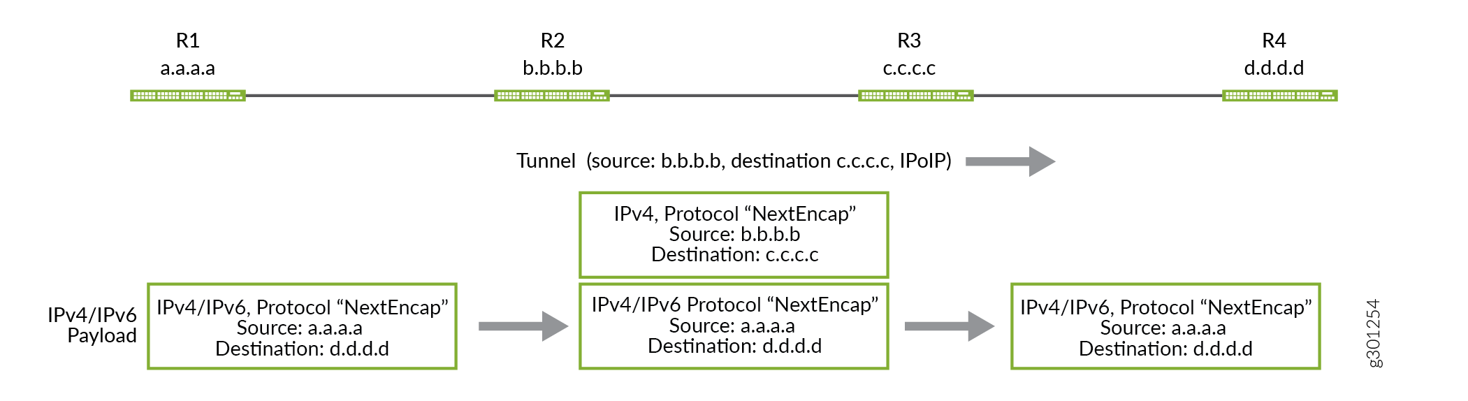
The following illustration depicts how IPv4 or IPv6 traffic are sent from R-1 to R-5 through an IP over IP tunnel established between R-2 and R-4:
IP-over-IP Tunnel Stitching
In Junos OS Release 21.3R1, we introduce IP-over-IP tunnel stitching on MX240, MX480, MX960, PTX1000, PTX10008, PTX10016, and QFX10002. You can use this feature to terminate an IP-over-IP tunnel on a device and initiate another tunnel on the same device. When a device receives the IP-over-IP packet, it de-encapsulates the outer packet header and inner packet lookup occurs. The inner IP packet header then points to another tunnel on the same device, where the same device encapsulates the packet again with another IP-over-IP header.
Example: Configuring Next-Hop-Based IP-Over-IP Dynamic Tunnels
Learn how to configure next hop-based tunnels by using IP-over-IP encapsulation.
- Requirements
- Overview
- Configuring IP-over-IP Dynamic Tunnels with a Protocol Next Hop
- Example: Configure an IPoIP Tunnel in an MPLS Environment with LDP tunnel, Resolved Through inetcolor.0 Using Static Configuration
- Example: Configure an IPoIP Tunnel with LDP tunnel in an MPLS Cloud, Resolved through inetcolor.0 Using BGP Signaling
- Verification
Requirements
This example uses the following hardware and software components:
5 MX Series routers.
Junos OS Release 20.3R1 or later version.
- See the Feature Explorer for supported platforms.
Overview
Starting in Junos OS Release 20.3R1, we support an IP-over-IP encapsulation to facilitate IP overlay construction over IP transport network. This example shows the establishment of unicast IP-over-IP tunnels between devices with a protocol next hop (PNH) through an IBGP peering between R2 and R4, which are connected over an OSPF core, to exchange routes and signal dynamic tunnels.
Topology
Figure 1 illustrates an IP-over-IP scenario with 5 devices.
In this example, we are exchanging routes from R1 to R5 and vice versa through
IP-over-IP dynamic tunnels established between the R2 and R4. Routes from R1 are
exported to R2 and routes from R5 are exported to R4, by using the protocol
IS-IS. We configure a unicast IPIP tunnel Tunnel-01 from R2
to R4 and another tunnel Tunnel-01 from R4 to R2. Route
prefixes that are generated within the network masks from the configured
destination-networks of the peer device are used for creating the tunnel and
traffic flows in the opposite direction of the routes in the
tunnel..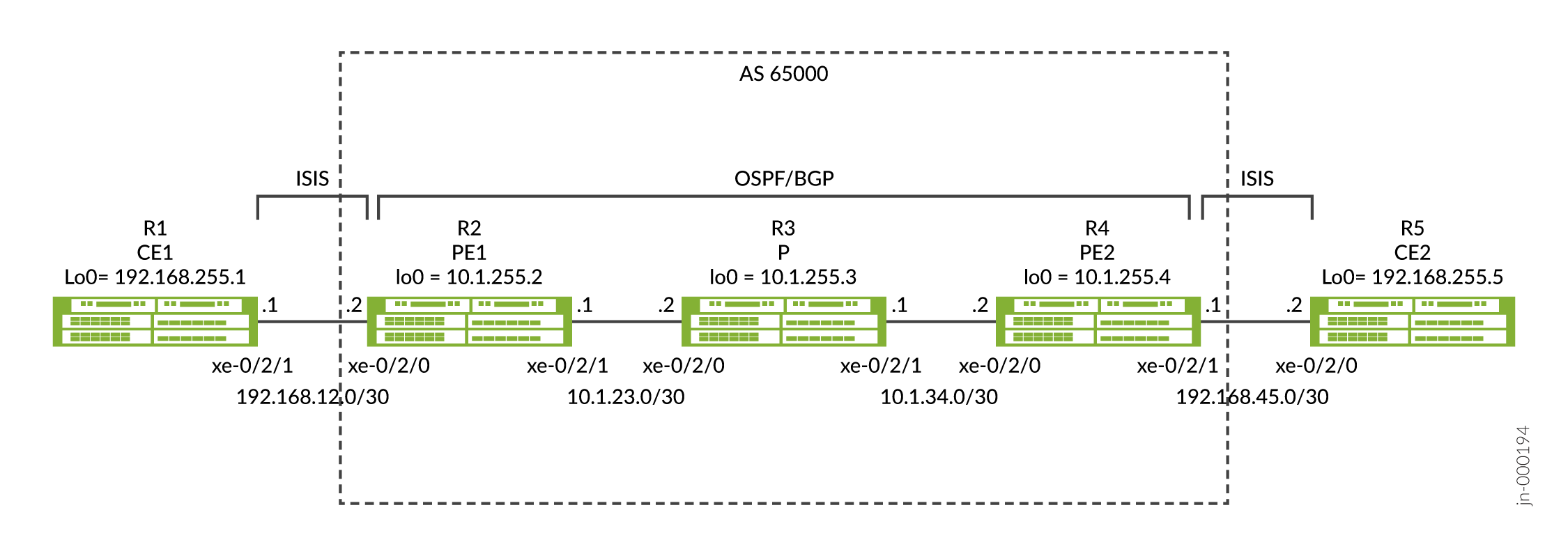
Configuring IP-over-IP Dynamic Tunnels with a Protocol Next Hop
CLI Quick Configuration
To quickly configure this example, copy the
following commands, paste them into a text file, remove any line breaks,
change any details necessary to match your network configuration,
copy and paste the commands into the CLI at the [edit] hierarchy
level, and then enter commit from configuration mode.
R1
set interfaces xe-0/2/0 unit 0 description R1-to-R2
set interfaces xe-0/2/0 unit 0 family inet address 192.168.12.1/30
set interfaces xe-0/2/0 unit 0 family iso
set interfaces lo0 unit 0 family inet address 192.168.255.1/32
set interfaces lo0 unit 0 family iso address 49.0001.1920.1682.5501.00
set routing-options router-id 192.168.255.1
set protocols isis interface xe-0/2/0.0
set protocols isis interface lo0.0
set protocols isis level 1 disable
R2
set interfaces xe-0/2/0 description R2-to-R1
set interfaces xe-0/2/0 unit 0 family inet address 192.168.12.2/30
set interfaces xe-0/2/0 unit 0 family iso
set interfaces xe-0/2/1 description R2-to-R3
set interfaces xe-0/2/1 unit 0 family inet address 10.1.23.1/30
set interfaces lo0 unit 0 family inet address 10.1.255.2/32
set interfaces lo0 unit 0 family iso address 49.0001.0010.1255.0002.00
set policy-options policy-statement export-bgp term t1 from protocol bgp
set policy-options policy-statement export-bgp term t1 then accept
set policy-options policy-statement export-isis term t1 from protocol isis
set policy-options policy-statement export-isis term t1 then next-hop self
set policy-options policy-statement export-isis term t1 then accept
set routing-options resolution rib inet.0 resolution-ribs inet.3
set routing-options router-id 10.1.255.2
set routing-options autonomous-system 65000
set routing-options dynamic-tunnels Tunnel-01 source-address 10.1.255.2
set routing-options dynamic-tunnels Tunnel-01 ipip
set routing-options dynamic-tunnels Tunnel-01 destination-networks 10.1.255.0/24
set protocols bgp group iBGP type internal
set protocols bgp group iBGP local-address 10.1.255.2
set protocols bgp group iBGP family inet unicast
set protocols bgp group iBGP export export-isis
set protocols bgp group iBGP neighbor 10.1.255.4
set protocols isis interface xe-0/2/0.0
set protocols isis interface lo0.0
set protocols isis level 1 disable
set protocols isis export export-bgp
set protocols ospf area 0.0.0.0 interface xe-0/2/1.0
set protocols ospf area 0.0.0.0 interface lo0.0
R3
set interfaces xe-0/2/0 unit 0 description R3-to-R2
set interfaces xe-0/2/0 unit 0 family inet address 10.1.23.2/30
set interfaces xe-0/2/1 unit 0 description R3-to-R4
set interfaces xe-0/2/1 unit 0 family inet address 10.1.34.1/30
set interfaces lo0 unit 0 family inet address 10.1.255.3/32
set routing-options router-id 10.1.255.3
set protocols ospf area 0.0.0.0 interface xe-0/2/0.0
set protocols ospf area 0.0.0.0 interface xe-0/2/1.0
set protocols ospf area 0.0.0.0 interface lo0.0 passive
R4
set interfaces xe-0/2/0 unit 0 description R4-to-R3
set interfaces xe-0/2/0 unit 0 family inet address 10.1.34.2/30
set interfaces xe-0/2/1 unit 0 description R4-to-R5
set interfaces xe-0/2/1 unit 0 family inet address 192.168.45.1/30
set interfaces xe-0/2/1 unit 0 family iso
set interfaces lo0 unit 0 family inet address 10.1.255.4/32
set interfaces lo0 unit 0 family iso address 49.0001.0010.1255.0004.00
set policy-options policy-statement export-bgp term t1 from protocol bgp
set policy-options policy-statement export-bgp term t1 then accept
set policy-options policy-statement export-isis term t1 from protocol isis
set policy-options policy-statement export-isis term t1 then next-hop self
set policy-options policy-statement export-isis term t1 then accept
set routing-options resolution rib inet.0 resolution-ribs inet.3
set routing-options router-id 10.1.255.4
set routing-options autonomous-system 65000
set routing-options dynamic-tunnels Tunnel-01 source-address 10.1.255.4
set routing-options dynamic-tunnels Tunnel-01 ipip
set routing-options dynamic-tunnels Tunnel-01 destination-networks 10.1.255.0/24
set protocols bgp group iBGP type internal
set protocols bgp group iBGP local-address 10.1.255.4
set protocols bgp group iBGP family inet unicast
set protocols bgp group iBGP export export-isis
set protocols bgp group iBGP neighbor 10.1.255.2
set protocols isis interface xe-0/2/1.0
set protocols isis interface lo0.0
set protocols isis level 1 disable
set protocols isis export export-bgp
set protocols ospf area 0.0.0.0 interface xe-0/2/0.0
set protocols ospf area 0.0.0.0 interface lo0.0
R5
set interfaces xe-0/2/0 unit 0 description R5-to-R4
set interfaces xe-0/2/0 unit 0 family inet address 192.168.45.2/30
set interfaces xe-0/2/0 unit 0 family iso
set interfaces lo0 unit 0 family inet address 192.168.255.5/32
set interfaces lo0 unit 0 family iso address 49.0001.1920.1682.5505.00
set routing-options router-id 192.168.255.5
set protocols isis interface xe-0/2/0.0
set protocols isis interface lo0.0
set protocols isis level 1 disable
Configuring IP-IP dynamic tunnels with a Protocol Next Hop
Step-by-Step Procedure for R1
R1 and R5 have a similar configuration so we will only show the step-by-step procedure for R1.
-
Enter configuration mode on R1.
-
Configure the interface connected to R2 and interface lo0. Make sure to configure both family
inetandiso. Familyisois needed for protocol IS-IS.[edit] user@R1# set interfaces xe-0/2/0 unit 0 description R1-to-R2 user@R1# set interfaces xe-0/2/0 unit 0 family inet address 192.168.12.1/30 user@R1# set interfaces xe-0/2/0 unit 0 family iso user@R1# set interfaces lo0 unit 0 family inet address 192.168.255.1/32 user@R1# set interfaces lo0 unit 0 family iso address 49.0001.1920.1682.5501.00
-
Configure the Router ID.
[edit]
user@R1# set routing-options router-id 192.168.255.1
-
Configure protocols IS-IS. Routes are advertised between R1 and R2 using the IS-IS protocol.
[edit]
user@R1# set protocols isis interface xe-0/2/0.0
user@R1# set protocols isis interface lo0.0
user@R1# set protocols isis level 1 disable
-
Enter
commiton R1 from the configuration mode.
Step-by-Step Procedure for R2
R2 and R4 have a similar configuration so we will only show the step-by-step procedure for R2.
-
Enter configuration mode on R2.
-
Configure the interfaces connected to R1 and R3 and interface lo0. Ensure to configure both family
inetandisoon the interface connected to R1 and lo0.[edit] user@R2# set interfaces xe-0/2/0 description R2-to-R1 user@R2# set interfaces xe-0/2/0 unit 0 family inet address 192.168.12.2/30 user@R2# set interfaces xe-0/2/0 unit 0 family iso user@R2# set interfaces xe-0/2/1 description R2-to-R3 user@R2# set interfaces xe-0/2/1 unit 0 family inet address 10.1.23.1/30 user@R2# set interfaces lo0 unit 0 family inet address 10.1.255.2/32 user@R2# set interfaces lo0 unit 0 family iso address 49.0001.0010.1255.0002.00
-
Configure protocols IS-IS for the interface connected to R1. The export policy to advertise BGP routes into IS-IS is shown in the policy configuration step.
[edit]
user@R2# set protocols isis interface xe-0/2/0.0
user@R2# set protocols isis interface lo0.0
user@R2# set protocols isis level 1 disable
user@R2# set protocols isis export export-bgp
-
Configure the OSPF protocol for the interface connected to R3 for lo0 reachability.
[edit]
user@R2# set protocols ospf area 0.0.0.0 interface xe-0/2/1.0
user@R2# set protocols ospf area 0.0.0.0 interface lo0.0
-
Configure the
router-idandautonomous-system, and IBGP between R2 and R4. The export policy to advertise IS-IS routes into BGP is shown in the policy configuration step.[edit] user@R2# set routing-options router-id 10.1.255.2 user@R2# set routing-options autonomous-system 65000 user@R2# set protocols bgp group iBGP type internal user@R2# set protocols bgp group iBGP local-address 10.1.255.2 user@R2# set protocols bgp group iBGP family inet unicast user@R2# set protocols bgp group iBGP export export-isis user@R2# set protocols bgp group iBGP neighbor 10.1.255.4
-
Configure the BGP and IS-IS export policies that were applied during the previous steps. The
export-bgppolicy is applied to protocols IS-IS as an export to advertise BGP routes into IS-IS and theexport-isispolicy is applied to BGP as an export to advertise IS-IS routes into BGP. The next-hop self option allows R2 to advertise the IS-IS routes into BGP with R2 as the next-hop instead of the interface next-hop of R1.[edit] user@R2# set policy-options policy-statement export-bgp term t1 from protocol bgp user@R2# set policy-options policy-statement export-bgp term t1 then accept user@R2# set policy-options policy-statement export-isis term t1 from protocol isis user@R2# set policy-options policy-statement export-isis term t1 then next-hop self user@R2# set policy-options policy-statement export-isis term t1 then accept
-
Configure the IP-IP dynamic tunnel Tunnel-01 from R2 to R4. The configuration option
resolution-ribs
                                    inet.3
allows for route resolution to take place in inet.3 and is needed to establish the tunnel.[edit] user@R2# set routing-options resolution rib inet.0 resolution-ribs inet.3 user@R2# set routing-options dynamic-tunnels Tunnel-01 source-address 10.1.255.2 user@R2# set routing-options dynamic-tunnels Tunnel-01 ipip user@R2# set routing-options dynamic-tunnels Tunnel-01 destination-networks 10.1.255.0/24
-
(Optional) - Alternative configuration for the IP-IP dynamic tunnel Tunnel-01 from R2 to R4. Instead of configuring the
resolution-ribs inet.3you can configure the tunnel preference lower than the protocol next-hop preference for the route to the tunnel endpoint. The route for R4 is learned using OSPF and has a preference of 10 and the default preference of the tunnel is 305. Configure the tunnel preference lower than the OSPF preference allows the tunnel to be preferred and to establish.[edit] user@R2# set routing-options dynamic-tunnels Tunnel-01 source-address 10.1.255.2 user@R2# set routing-options dynamic-tunnels Tunnel-01 ipip user@R2# set routing-options dynamic-tunnels Tunnel-01 destination-networks 10.1.255.0/24 preference 9
-
Enter
commitfrom the configuration mode on R2.
Step-by-Step Procedure for R3
-
Enter configuration mode on R3.
-
Configure the interfaces connected to R2 and R4 and interface lo0.
[edit]
user@R3# set interfaces xe-0/2/0 unit 0 description R3-to-R2
user@R3# set interfaces xe-0/2/0 unit 0 family inet address 10.1.23.2/30
user@R3# set interfaces xe-0/2/1 unit 0 description R3-to-R4
user@R3# set interfaces xe-0/2/1 unit 0 family inet address 10.1.34.1/30
user@R3# set interfaces lo0 unit 0 family inet address 10.1.255.3/32
-
Configure the Router ID.
[edit]
user@R3# set routing-options router-id 10.1.255.3
-
Configure the OSPF protocol for the interfaces connected to R2 and R4 for lo0 reachability.
[edit]
user@R3# set protocols ospf area 0.0.0.0 interface xe-0/2/0.0
user@R3# set protocols ospf area 0.0.0.0 interface xe-0/2/1.0
user@R3# set protocols ospf area 0.0.0.0 interface lo0.0 passive
-
Enter
commitfrom configuration mode on R3 device.
Results
Verify your configuration by checking the below configurations from devices as follows:
Here's how you can verify configurations on R2:
user@R2# show interfaces
xe-0/2/0 {
    description R2-to-R1;
    unit 0 {
        family inet {
            address 192.168.12.2/30;
        }
        family iso;
    }
}
xe-0/2/1 {
    description R2-to-R3;
    unit 0 {
        family inet {
            address 10.1.23.1/30;
        }
    }
}
lo0 {
    unit 0 {
        family inet {
            address 10.1.255.2/32;
        }
        family iso {
            address 49.0001.0010.1255.0002.00;
        }
    }
}
user@R2# show routing-options
resolution {
    rib inet.0 {
        resolution-ribs inet.3;
    }
}
router-id 10.1.255.2;
autonomous-system 65000;
dynamic-tunnels {
    Tunnel-01 {
        source-address 10.1.255.2;
        ipip;
        destination-networks {
            10.1.255.0/24;
        }
    }
}
user@R2# show protocols
bgp {
    group iBGP {
        type internal;
        local-address 10.1.255.2;
        family inet {
            unicast;
        }
        export export-isis;
        neighbor 10.1.255.4;
    }
}
isis {
    interface xe-0/2/0.0;
    interface lo0.0;
    level 1 disable;
    export export-bgp;
}
ospf {
    area 0.0.0.0 {
        interface xe-0/2/1.0;
        interface lo0.0;
    }
}
user@R2# show policy-options
policy-statement export-bgp {
    term t1 {
        from protocol bgp;
        then accept;
    }
}
policy-statement export-isis {
    term t1 {
        from protocol isis;
        then {
            next-hop self;
            accept;
        }
    }
}
Verification
- Verify Dynamic Tunnel Database
- Verify Route Table in inet.3
- Verify BGP Routes Using the Tunnel
- Verify End-to-End Reachability
Verify Dynamic Tunnel Database
Purpose
To verify the dynamic tunnel database information, use the show
dynamic-tunnels database operational mode command.
Action
user@R2> show dynamic-tunnels database
*- Signal Tunnels #- PFE-down
Table: inet.3

Destination-network: 10.1.255.0/24

Tunnel to: 10.1.255.4/32
  Reference count: 3
  Next-hop type: IPoIP (forwarding-nexthop)
    Source address: 10.1.255.2
    Next hop: tunnel-composite, 0x76b6c50, nhid 515
      Reference count: 2
      Ingress Route: [OSPF] 10.1.255.4/32, via metric 2
      Traffic Statistics: Packets 0, Bytes 0
      State: Up
  Aggregate Traffic Statistics:
    Tunnel Encapsulation: Dest 10.1.255.4, Src 10.1.255.2, IPoIP, Tunnel-Id 1
Traffic Statistics: Packets 0, Bytes 0 user@R4> show dynamic-tunnels database
*- Signal Tunnels #- PFE-down
Table: inet.3
Destination-network: 10.1.255.0/24
Tunnel to: 10.1.255.2/32
Reference count: 3
Next-hop type: IPoIP (forwarding-nexthop)
Source address: 10.1.255.4
Next hop: tunnel-composite, 0x76b6c50, nhid 513
Reference count: 2
Ingress Route: [OSPF] 10.1.255.2/32, via metric 2
Traffic Statistics: Packets 0, Bytes 0
State: Up
Aggregate Traffic Statistics:
Tunnel Encapsulation: Dest 10.1.255.2, Src 10.1.255.4, IPoIP, Tunnel-Id 1
Traffic Statistics: Packets 0, Bytes 0Meaning
The output indicates that an IPoIP tunnel is established between R2
(192.168.0.21 source) and R4
(192.168.0.41 destination) and another IPoIP tunnel
is established between R4 (192.168.0.41 source) and R2
(192.168.0.21 destination).
Verify Route Table in inet.3
Purpose
To verify routes generated on inet.3 table, use the show route
table inet.3 operational mode command.
Action
user@R2> show route table inet.3

inet.3: 2 destinations, 2 routes (2 active, 0 holddown, 0 hidden)
+ = Active Route, - = Last Active, * = Both

10.1.255.0/24      *[Tunnel/305] 02:02:44
                       Tunnel
10.1.255.4/32      *[Tunnel/305] 02:02:44, metric 2
Tunnel Composite, IPoIP (src 10.1.255.2 dest 10.1.255.4)user@R4> show route table inet.3
inet.3: 2 destinations, 2 routes (2 active, 0 holddown, 0 hidden)
+ = Active Route, - = Last Active, * = Both
10.1.255.0/24 *[Tunnel/305] 6d 01:35:50
Tunnel
10.1.255.2/32 *[Tunnel/305] 6d 01:35:48, metric 2
Tunnel Composite, IPoIP (src 10.1.255.4 dest 10.1.255.2)Meaning
The output indicates the route used for resolving the BGP traffic that will use the tunnel.
Verify BGP Routes Using the Tunnel
Purpose
To verify BGP routes received on R2 and R4 for R1 and R5 are using the tunnel.
Action
user@R2> show route protocol bgp

inet.0: 17 destinations, 17 routes (17 active, 0 holddown, 0 hidden)
+ = Active Route, - = Last Active, * = Both

192.168.255.5/32   *[BGP/170] 02:42:48, MED 10, localpref 100, from 10.1.255.4
                      AS path: I, validation-state: unverified
                    >  via Tunnel Composite, IPoIP (src 10.1.255.2 dest 10.1.255.4)

inet.3: 2 destinations, 2 routes (2 active, 0 holddown, 0 hidden)

iso.0: 1 destinations, 1 routes (1 active, 0 holddown, 0 hidden)

inet6.0: 1 destinations, 1 routes (1 active, 0 holddown, 0 hidden)user@R4> show route protocol bgp
inet.0: 17 destinations, 17 routes (17 active, 0 holddown, 0 hidden)
+ = Active Route, - = Last Active, * = Both
192.168.255.1/32 *[BGP/170] 00:13:30, MED 10, localpref 100, from 10.1.255.2
AS path: I, validation-state: unverified
> via Tunnel Composite, IPoIP (src 10.1.255.4 dest 10.1.255.2)
inet.3: 2 destinations, 2 routes (2 active, 0 holddown, 0 hidden)
iso.0: 1 destinations, 1 routes (1 active, 0 holddown, 0 hidden)
inet6.0: 1 destinations, 1 routes (1 active, 0 holddown, 0 hidden)Meaning
The output indicates that R2 is using the tunnel for the BGP route to R5, and R4 is using the tunnel for the BGP route to R1.
Verify End-to-End Reachability
Purpose
Verify R1 can ping R5 by using the ping 192.168.255.5 source
192.168.255.1 count 2 operational mode command.
Action
user@R1>ping 192.168.255.5 source 192.168.255.1 count 2
PING 192.168.255.5 (192.168.255.5): 56 data bytes
64 bytes from 192.168.255.5: icmp_seq=0 ttl=62 time=5.565 ms
64 bytes from 192.168.255.5: icmp_seq=1 ttl=62 time=5.957 ms

--- 192.168.255.5 ping statistics ---
2 packets transmitted, 2 packets received, 0% packet loss
round-trip min/avg/max/stddev = 5.565/5.761/5.957/0.196 ms
Meaning
The output from R1 shows that R1 can ping R5.
Example: Configure an IPoIP Tunnel in an MPLS Environment with LDP tunnel, Resolved Through inetcolor.0 Using Static Configuration
By default, MPLS has a higher preference than IP. For example, with MPLS and LDP configured among R2, R3, and R4, wherein R2 is reachable with R4 through LDP, routes from R2 will get resolved over LDP, instead of IP-over-IP, because of the higher preference.
If you prefer to have a particular route to resolve over the IP-over-IP instead of LDP, you can do so by creating an inetcolor table, where IP-over-IP has a higher preference and setting BGP to resolve that route over inetcolor table instead of inet3 table. The following example shows you how to do so by using static configuration.
Topology
In this example, we are exchanging routes from R1 to R5 and vice versa through
IP-over-IP dynamic tunnels established between the R2 and R4. Routes from R1 are
exported to R2 and routes from R5 are exported to R4, by using the protocol
IS-IS. We configure a unicast IPIP tunnel Tunnel-01 from R2
to R4 and another tunnel Tunnel-01 from R4 to R2. Route
prefixes that are generated within the network masks from the configured
destination-networks of the peer device are used for creating the tunnel and
traffic flows in the opposite direction of the routes in the tunnel.
CLI Quick Configuration
R1
set interfaces xe-0/2/0 unit 0 description R1-to-R2
set interfaces xe-0/2/0 unit 0 family inet address 192.168.12.1/30
set interfaces xe-0/2/0 unit 0 family iso
set interfaces lo0 unit 0 family inet address 192.168.255.1/32
set interfaces lo0 unit 0 family iso address 49.0001.1920.1682.5501.00
set routing-options router-id 192.168.255.1
set protocols isis interface xe-0/2/0.0
set protocols isis interface lo0.0
set protocols isis level 1 disable
R2
set interfaces xe-0/2/0 description R2-to-R1
set interfaces xe-0/2/0 unit 0 family inet address 192.168.12.2/30
set interfaces xe-0/2/0 unit 0 family iso
set interfaces xe-0/2/1 description R2-to-R3
set interfaces xe-0/2/1 unit 0 family inet address 10.1.23.1/30
set interfaces xe-0/2/1 unit 0 family mpls
set interfaces lo0 unit 0 family inet address 10.1.255.2/32
set interfaces lo0 unit 0 family iso address 49.0001.0010.1255.0002.00
set policy-options policy-statement export-bgp term t1 from protocol bgp
set policy-options policy-statement export-bgp term t1 then accept
set policy-options policy-statement export-isis term t1 from protocol isis
set policy-options policy-statement export-isis term t1 then next-hop self
set policy-options policy-statement export-isis term t1 then accept
set policy-options policy-statement ipip-tunnel-color term term-01 from route-filter 192.168.255.5/32 exact
set policy-options policy-statement ipip-tunnel-color term term-01 then community add red
set policy-options policy-statement ipip-tunnel-color term term-01 then accept
set policy-options policy-statement set-dynamic-tunnel-ep term t1 from route-filter 10.1.255.4/32 exact
set policy-options policy-statement set-dynamic-tunnel-ep term t1 then tunnel-end-point-address 10.1.255.4
set policy-options policy-statement set-dynamic-tunnel-ep term t1 then accept
set policy-options community red members color:0:100
set routing-options router-id 10.1.255.2
set routing-options autonomous-system 65000
set routing-options dynamic-tunnels Tunnel-01 source-address 10.1.255.2
set routing-options dynamic-tunnels Tunnel-01 ipip
set routing-options dynamic-tunnels Tunnel-01 destination-networks 10.1.255.0/24 dyn-tunnel-attribute-policy set-dynamic-tunnel-ep
set routing-options dynamic-tunnels Tunnel-01 destination-networks 10.1.255.0/24 colors 100
set protocols bgp group iBGP type internal
set protocols bgp group iBGP local-address 10.1.255.2
set protocols bgp group iBGP import ipip-tunnel-color
set protocols bgp group iBGP family inet unicast extended-nexthop-color
set protocols bgp group iBGP export export-isis
set protocols bgp group iBGP neighbor 10.1.255.4
set protocols isis interface xe-0/2/0.0
set protocols isis interface lo0.0
set protocols isis level 1 disable
set protocols isis export export-bgp
set protocols ldp interface xe-0/2/1.0
set protocols mpls interface xe-0/2/1.0
set protocols ospf area 0.0.0.0 interface xe-0/2/1.0
set protocols ospf area 0.0.0.0 interface lo0.0
R3
set interfaces xe-0/2/0 unit 0 description R3-to-R2
set interfaces xe-0/2/0 unit 0 family inet address 10.1.23.2/30
set interfaces xe-0/2/0 unit 0 family mpls
set interfaces xe-0/2/1 unit 0 description R3-to-R4
set interfaces xe-0/2/1 unit 0 family inet address 10.1.34.1/30
set interfaces xe-0/2/1 unit 0 family mpls
set interfaces lo0 unit 0 family inet address 10.1.255.3/32
set routing-options router-id 10.1.255.3
set protocols ldp interface xe-0/2/0.0
set protocols ldp interface xe-0/2/1.0
set protocols mpls interface xe-0/2/0.0
set protocols mpls interface xe-0/2/1.0
set protocols ospf area 0.0.0.0 interface xe-0/2/0.0
set protocols ospf area 0.0.0.0 interface xe-0/2/1.0
set protocols ospf area 0.0.0.0 interface lo0.0 passive
R4
set interfaces xe-0/2/0 unit 0 description R4-to-R3
set interfaces xe-0/2/0 unit 0 family inet address 10.1.34.2/30
set interfaces xe-0/2/0 unit 0 family mpls
set interfaces xe-0/2/1 unit 0 description R4-to-R5
set interfaces xe-0/2/1 unit 0 family inet address 192.168.45.1/30
set interfaces xe-0/2/1 unit 0 family iso
set interfaces lo0 unit 0 family inet address 10.1.255.4/32
set interfaces lo0 unit 0 family iso address 49.0001.0010.1255.0004.00
set policy-options policy-statement export-bgp term t1 from protocol bgp
set policy-options policy-statement export-bgp term t1 then accept
set policy-options policy-statement export-isis term t1 from protocol isis
set policy-options policy-statement export-isis term t1 then next-hop self
set policy-options policy-statement export-isis term t1 then accept
set policy-options policy-statement ipip-tunnel-color term term-01 from route-filter 192.168.255.1/32 exact
set policy-options policy-statement ipip-tunnel-color term term-01 then community add red
set policy-options policy-statement ipip-tunnel-color term term-01 then accept
set policy-options policy-statement set-dynamic-tunnel-ep term t1 from route-filter 10.1.255.2/32 exact
set policy-options policy-statement set-dynamic-tunnel-ep term t1 then tunnel-end-point-address 10.1.255.2
set policy-options policy-statement set-dynamic-tunnel-ep term t1 then accept
set policy-options community red members color:0:100
set routing-options router-id 10.1.255.4
set routing-options autonomous-system 65000
set routing-options dynamic-tunnels Tunnel-01 source-address 10.1.255.4
set routing-options dynamic-tunnels Tunnel-01 ipip
set routing-options dynamic-tunnels Tunnel-01 destination-networks 10.1.255.0/24 dyn-tunnel-attribute-policy set-dynamic-tunnel-ep
set routing-options dynamic-tunnels Tunnel-01 destination-networks 10.1.255.0/24 colors 100
set protocols bgp group iBGP type internal
set protocols bgp group iBGP local-address 10.1.255.4
set protocols bgp group iBGP import ipip-tunnel-color
set protocols bgp group iBGP family inet unicast extended-nexthop-color
set protocols bgp group iBGP export export-isis
set protocols bgp group iBGP neighbor 10.1.255.2
set protocols isis interface xe-0/2/1.0
set protocols isis interface lo0.0
set protocols isis level 1 disable
set protocols isis export export-bgp
set protocols ldp interface xe-0/2/0.0
set protocols mpls interface xe-0/2/0.0
set protocols ospf area 0.0.0.0 interface xe-0/2/0.0
set protocols ospf area 0.0.0.0 interface lo0.0
R5
set interfaces xe-0/2/0 unit 0 description R5-to-R4
set interfaces xe-0/2/0 unit 0 family inet address 192.168.45.2/30
set interfaces xe-0/2/0 unit 0 family iso
set interfaces lo0 unit 0 family inet address 192.168.255.5/32
set interfaces lo0 unit 0 family iso address 49.0001.1920.1682.5505.00
set routing-options router-id 192.168.255.5
set protocols isis interface xe-0/2/0.0
set protocols isis interface lo0.0
set protocols isis level 1 disable
Procedure
Step-by-Step Procedure for R1
R1 and R5 have a similar configuration so we will only show the step-by-step procedure for R1.
-
Enter configuration mode on R1.
-
Configure the interface connected to R2 and interface lo0. Make sure to configure both family
inetandiso. Familyisois needed for protocol IS-IS.[edit] user@R1# set interfaces xe-0/2/0 unit 0 description R1-to-R2 user@R1# set interfaces xe-0/2/0 unit 0 family inet address 192.168.12.1/30 user@R1# set interfaces xe-0/2/0 unit 0 family iso user@R1# set interfaces lo0 unit 0 family inet address 192.168.255.1/32 user@R1# set interfaces lo0 unit 0 family iso address 49.0001.1920.1682.5501.00
-
Configure the Router ID.
[edit]
user@R1# set routing-options router-id 192.168.255.1
-
Configure protocols IS-IS. Routes are advertised between R1 and R2 using the IS-IS protocol.
[edit]
user@R1# set protocols isis interface xe-0/2/0.0
user@R1# set protocols isis interface lo0.0
user@R1# set protocols isis level 1 disable
-
Enter
commiton R1 from the configuration mode.
Step-by-Step Procedure for R2
R2 and R4 have a similar configuration so we will only show the step-by-step procedure for R2.
-
Enter configuration mode on R2.
-
Configure the interfaces connected to R1 and R3 and interface lo0. Ensure to configure both family
inetandisoon the interface connected to R1 and lo0, and to configure both familyinetandmplson the interface connected to R3.[edit] user@R2# set interfaces xe-0/2/0 description R2-to-R1 user@R2# set interfaces xe-0/2/0 unit 0 family inet address 192.168.12.2/30 user@R2# set interfaces xe-0/2/0 unit 0 family iso user@R2# set interfaces xe-0/2/1 description R2-to-R3 user@R2# set interfaces xe-0/2/1 unit 0 family inet address 10.1.23.1/30 user@R2# set interfaces xe-0/2/0 unit 0 family mpls user@R2# set interfaces lo0 unit 0 family inet address 10.1.255.2/32 user@R2# set interfaces lo0 unit 0 family iso address 49.0001.0010.1255.0002.00
-
Configure protocols IS-IS for the interface connected to R1. The export policy to advertise BGP routes into IS-IS is shown in the policy configuration step.
[edit]
user@R2# set protocols isis interface xe-0/2/0.0
user@R2# set protocols isis interface lo0.0
user@R2# set protocols isis level 1 disable
user@R2# set protocols isis export export-bgp
-
Configure the OSPF protocol for the interface connected to R3 for lo0 reachability.
[edit]
user@R2# set protocols ospf area 0.0.0.0 interface xe-0/2/1.0
user@R2# set protocols ospf area 0.0.0.0 interface lo0.0
-
Configure the LDP and MPLS protocols for the interface connected to R3.
[edit]
user@R2# set protocols ldp interface xe-0/2/1.0
user@R2# set protocols mpls interface xe-0/2/1.0
-
Configure the
router-idandautonomous-systemunder therouting-optionshierarchy, and configure IBGP between R2 and R4. The import policy to add a community to the routes learned using BGP and the export policy to advertise IS-IS routes into BGP is shown in the policy configuration step. Ensure to includeextended-nexthop-coloroption to thefamily inet unicastconfiguration to allow resolution using the inetcolor.0 table.[edit] user@R2# set routing-options router-id 10.1.255.2 user@R2# set routing-options autonomous-system 65000 user@R2# set protocols bgp group iBGP type internal user@R2# set protocols bgp group iBGP local-address 10.1.255.2 user@R2# set protocols bgp group iBGP import ipip-tunnel-color user@R2# set protocols bgp group iBGP family inet unicast extended-nexthop-color user@R2# set protocols bgp group iBGP export export-isis user@R2# set protocols bgp group iBGP neighbor 10.1.255.4
-
Configure the IP-IP dynamic tunnel Tunnel-01 from R2 to R4. The
colorsconfiguration option allows the tunnel to be created in the inetcolor.0 route table. Thedyn-tunnel-attribute-policyset-dynamic-tunnel-ep configures a static tunnel endpoint. The policy is shown with the policy configuration step.[edit] user@R2# set routing-options dynamic-tunnels Tunnel-01 source-address 10.1.255.2 user@R2# set routing-options dynamic-tunnels Tunnel-01 ipip user@R2# set routing-options dynamic-tunnels Tunnel-01 destination-networks 10.1.255.0/24 dyn-tunnel-attribute-policy set-dynamic-tunnel-ep user@R2# set routing-options dynamic-tunnels Tunnel-01 destination-networks 10.1.255.0/24 colors 100
-
Configure the policies that were applied during the previous configuration steps. The export-bgp policy advertises BGP routes into IS-IS. The export-isis policy advertises IS-IS routes into BGP with changing the next-hop to R2. The ipip-tunnel-color policy applies the community to the route that is matched on in the
colorsconfiguration for the dynamic tunnel. The set-dynamic-tunnel-ep policy configures R4 as the tunnel endpoint.[edit] user@R2# set policy-options policy-statement export-bgp term t1 from protocol bgp user@R2# set policy-options policy-statement export-bgp term t1 then accept user@R2# set policy-options policy-statement export-isis term t1 from protocol isis user@R2# set policy-options policy-statement export-isis term t1 then next-hop self user@R2# set policy-options policy-statement export-isis term t1 then accept user@R2# set policy-options policy-statement ipip-tunnel-color term term-01 from route-filter 192.168.255.5/32 exact user@R2# set policy-options policy-statement ipip-tunnel-color term term-01 then community add red user@R2# set policy-options policy-statement ipip-tunnel-color term term-01 then accept user@R2# set policy-options policy-statement set-dynamic-tunnel-ep term t1 from route-filter 10.1.255.4/32 exact user@R2# set policy-options policy-statement set-dynamic-tunnel-ep term t1 then tunnel-end-point-address 10.1.255.4 user@R2# set policy-options policy-statement set-dynamic-tunnel-ep term t1 then accept user@R2# set policy-options community red members color:0:100
-
Enter
commitfrom the configuration mode.
Step-by-Step Procedure for R3
-
Enter configuration mode on R3.
-
Configure the interfaces connected to R2 and R4 and interface lo0. Ensure to configure both family
inetandmplson the interfaces connected to R2 and R4.[edit] user@R3# set interfaces xe-0/2/0 unit 0 description R3-to-R2 user@R3# set interfaces xe-0/2/0 unit 0 family inet address 10.1.23.2/30 user@R3# set interfaces xe-0/2/0 unit 0 family mpls user@R3# set interfaces xe-0/2/1 unit 0 description R3-to-R4 user@R3# set interfaces xe-0/2/1 unit 0 family inet address 10.1.34.1/30 user@R3# set interfaces xe-0/2/1 unit 0 family mpls user@R3# set interfaces lo0 unit 0 family inet address 10.1.255.3/32
-
Configure the Router ID.
[edit]
user@R3# set routing-options router-id 10.1.255.3
-
Configure the OSPF protocol for the interfaces connected to R2 and R4 for lo0 reachability.
[edit]
user@R3# set protocols ospf area 0.0.0.0 interface xe-0/2/0.0
user@R3# set protocols ospf area 0.0.0.0 interface xe-0/2/1.0
user@R3# set protocols ospf area 0.0.0.0 interface lo0.0 passive
-
Configure the LDP and MPLS protocols for the interfaces connected to R2 and R4.
[edit]
user@R2# set protocols ldp interface xe-0/2/0.0
user@R2# set protocols ldp interface xe-0/2/1.0
user@R2# set protocols mpls interface xe-0/2/0.0
user@R2# set protocols mpls interface xe-0/2/1.0
-
Enter
commitfrom configuration mode on R3 device.
Results
Verify your configuration by checking the below configurations from the devices.
Here's how you can check the configurations on R2:
user@R2# show interfaces
xe-0/2/0 {
    description R2-to-R1;
    unit 0 {
        family inet {
            address 192.168.12.2/30;
        }
        family iso;
    }
}
xe-0/2/1 {
    description R2-to-R3;
    unit 0 {
        family inet {
            address 10.1.23.1/30;
        }
        family mpls;
    }
}
lo0 {
    apply-groups-except global;
    unit 0 {
        family inet {
            address 10.1.255.2/32;
        }
        family iso {
            address 49.0001.0010.1255.0002.00;
        }
    }
}
user@R2# show protocols
bgp {
    group iBGP {
        type internal;
        local-address 10.1.255.2;
        import ipip-tunnel-color;
        family inet {
            unicast {
                extended-nexthop-color;
            }
        }
        export export-isis;
        neighbor 10.1.255.4;
    }
}
isis {
    interface xe-0/2/0.0;
    interface lo0.0;
    level 1 disable;
    export export-bgp;
}
ldp {
    interface xe-0/2/1.0;
}
mpls {
    interface xe-0/2/1.0;
}
ospf {
    area 0.0.0.0 {
        interface xe-0/2/1.0;
        interface lo0.0;
    }
}
user@R2#show routing-options
router-id 10.1.255.2;
autonomous-system 65000;
dynamic-tunnels {
    Tunnel-01 {
        source-address 10.1.255.2;
        ipip;
        destination-networks {
            10.1.255.0/24 {
                dyn-tunnel-attribute-policy set-dynamic-tunnel-ep;
                colors 100;
            }
        }
    }
}
user@R2#show policy-options
policy-statement export-bgp {
    term t1 {
        from protocol bgp;
        then accept;
    }
}
policy-statement export-isis {
    term t1 {
        from protocol isis;
        then {
            next-hop self;
            accept;
        }
    }
}
policy-statement ipip-tunnel-color {
    term term-01 {
        from {
            route-filter 192.168.255.5/32 exact;
        }
        then {
            community add red;
            accept;
        }
    }
}
policy-statement set-dynamic-tunnel-ep {
    term t1 {
        from {
            route-filter 10.1.255.4/32 exact;
        }
        then {
            tunnel-end-point-address 10.1.255.4;
            accept;
        }
    }
}
community red members color:0:100;
Verification
- Verify Route Resolution
- Verify Dynamic Tunnel Database
- Verify Route Next-Hops
- Verify End-to-End Reachability
Verify Route Resolution
Purpose
To verify the route resolution of routes in both inet.3 and inetcolor.0
tables, use the show route table inet.3 and
show route table inetcolor.0 operational mode
commands.
Action
user@R2> show route table inet.3

inet.3: 3 destinations, 4 routes (3 active, 0 holddown, 0 hidden)
+ = Active Route, - = Last Active, * = Both

10.1.255.0/24      *[Tunnel/305] 00:12:21
                       Tunnel
10.1.255.3/32      *[LDP/9] 1d 19:37:01, metric 1
                    >  to 10.1.23.2 via xe-0/2/1.0
10.1.255.4/32      *[LDP/9] 1d 19:32:25, metric 1
                    >  to 10.1.23.2 via xe-0/2/1.0, Push 299792
                    [Tunnel/305] 00:13:38, metric 2
Tunnel Composite, IPoIP (src 10.1.255.2 dest 10.1.255.4)user@R2> show route table inetcolor.0
inetcolor.0: 2 destinations, 2 routes (2 active, 0 holddown, 0 hidden)
+ = Active Route, - = Last Active, * = Both
10.1.255.0-0<c>/24
*[Tunnel/305] 00:13:26
Tunnel
10.1.255.4-100<c>/64
*[Tunnel/305] 00:13:26, metric 2
Tunnel Composite, IPoIP (src 10.1.255.2 dest 10.1.255.4-100<c>)Meaning
The R2 output indicates that on inet.3 table, the route
10.1.255.4 is getting resolved by LDP because of
higher preference than IP-over-IP. On the other hand, in the newly
created inetcolor.0 table, the route 10.1.255.4 is
getting resolved through IP-over-IP tunnel with
<c> attached.
Verify Dynamic Tunnel Database
Purpose
To verify the IP-over-IP dynamic tunnel created by routes in the
inetcolor.0 table, use the show dynamic-tunnels database
terse operational mode command.
Action
user@R2>show dynamic-tunnels database terse
*- Signal Tunnels #- PFE-down
Table: inet.3

Destination-network: 10.1.255.0/24

*- Signal Tunnels #- PFE-down
Table: inetcolor.0

Destination-network: 10.1.255.0-0<c>/24
Destination                      Source          Next-hop                 Type       Status
10.1.255.4-100<c>/64             10.1.255.2      0x76b71cc nhid 592       IPoIP      Up (via metric 2, tunnel-endpoint 10.1.255.4)
Meaning
The R2 output indicates that the route 192.168.0.41 has
created a next-hop-based dynamic tunnel.
Verify Route Next-Hops
Purpose
To verify all next-hops of the route that is set to resolve through
IP-over-IP, use the show route 192.168.255.5 extensive
expanded-nh operational mode command.
Action
user@R2>show route 192.168.255.5 extensive expanded-nh

inet.0: 18 destinations, 18 routes (18 active, 0 holddown, 0 hidden)
192.168.255.5/32 (1 entry, 1 announced)
Installed-nexthop:
Indr Composite (0x76b7238) 10.1.255.4-100<c>
  Krt_cnh (0x6fb1928) Index:593
    Krt_inh (0x7164d3c) Index:1048575 PNH: 10.1.255.4-100<c>
      Tun-comp (0x76b71cc) Index:592 IPoIP src 10.1.255.2 dest 10.1.255.4-100<c> tunnel-endpoint 10.1.255.4
TSI:
KRT in-kernel 192.168.255.5/32 -> {composite(593)}
IS-IS level 2, LSP fragment 0
        *BGP    Preference: 170/-101
                Next hop type: Indirect, Next hop index: 0
                Address: 0x76b7238
                Next-hop reference count: 2
                Source: 10.1.255.4
                Next hop type: Tunnel Composite, Next hop index: 592
                Next hop: via Tunnel Composite, IPoIP (src 10.1.255.2 dest 10.1.255.4-100<c> tunnel-endpoint 10.1.255.4), selected
                Protocol next hop: 10.1.255.4-100<c>
                Composite next hop: 0x6fb1928 593 INH Session ID: 0
                Indirect next hop: 0x7164d3c 1048575 INH Session ID: 0
                State: <Active Int Ext>
                Local AS: 65000 Peer AS: 65000
                Age: 20:14      Metric: 10      Metric2: 2
                Validation State: unverified
                Task: BGP_65000.10.1.255.4
                Announcement bits (2): 0-KRT 5-IS-IS
                AS path: I
                Communities: color:0:100
                Accepted
                Localpref: 100
                Router ID: 10.1.255.4
                Route-nexthop:
                Indr (0x76b7238) 10.1.255.4-100<c>
                  Krt_cnh (0x6fb1928) Index:593
                    Krt_inh (0x7164d3c) Index:1048575
                      Tun-comp (0x76b71cc) Index:592
                Thread: junos-main
                Composite next hops: 1
                        Protocol next hop: 10.1.255.4-100<c> Metric: 2
                        Composite next hop: 0x6fb1928 593 INH Session ID: 0
                        Indirect next hop: 0x7164d3c 1048575 INH Session ID: 0
                        Indirect path forwarding next hops: 1
                                Next hop type: Tunnel Composite
                                Tunnel type: IPoIP, (forwarding-nexthop), Reference count: 2, nhid: 592
                                Destination address: 10.1.255.4-100<c>, Source address: 10.1.255.2
                                Tunnel endpoint: 10.1.255.4
                                10.1.255.4-100<c>/64 Originating RIB: inetcolor.0
                                  Metric: 2 Node path count: 1
                                  Forwarding nexthops: 1
                                        Next hop type: Tunnel Composite
                                        Tunnel type: IPoIP, (extended-attr), Reference count: 1, nhid: 0
                                        Destination address: 10.1.255.4-100<c>, Source address: 10.1.255.2
Meaning
The output from R2 shows the expanded next hop for the
192.168.255.5 route. As R2 is an MX Series router,
it sends a protocol next hop and an indirect next hop.
Verify End-to-End Reachability
Purpose
Verify R1 can ping R5 by using the ping 192.168.255.5 source
192.168.255.1 count 2 operational mode command.
Action
user@R1>ping 192.168.255.5 source 192.168.255.1 count 2
PING 192.168.255.5 (192.168.255.5): 56 data bytes
64 bytes from 192.168.255.5: icmp_seq=0 ttl=62 time=6.009 ms
64 bytes from 192.168.255.5: icmp_seq=1 ttl=62 time=5.398 ms

--- 192.168.255.5 ping statistics ---
2 packets transmitted, 2 packets received, 0% packet loss
round-trip min/avg/max/stddev = 5.398/5.704/6.009/0.306 ms
Meaning
The output from R1 shows that R1 can ping R5.
Example: Configure an IPoIP Tunnel with LDP tunnel in an MPLS Cloud, Resolved through inetcolor.0 Using BGP Signaling
In an MPLS environment with LDP enabled, BGP routes get resolved through LDP on inet.3 table because MPLS has higher preference than IP.
If you still prefer to have your routes resolved through IP-over-IP in the MPLS environment, you can do so by creating an inetcolor.0 table that assigns higher preference for IP-over-IP and resolve chosen routes through IP-over-IP. To enable this feature by using BGP, the route resolution is performed on the remote end device of the tunnel and with the export policy configured on the remote device, routes are received and advertised through BGP signaling. This example shows how to configure this by using the BGP protocol configuration.
In this example, we are exchanging routes from R1 to R5 and vice versa through
IP-over-IP dynamic tunnels established between the R2 and R4. Routes from R1 are
exported to R2 and routes from R5 are exported to R4, by using the protocol IS-IS.
We configure a unicast IPIP tunnel Tunnel-01 from R2 to R4 and
another tunnel Tunnel-01 from R4 to R2. Route prefixes that are
generated within the network masks from the configured destination-networks of the
peer device are used for creating the tunnel and traffic flows in the opposite
direction of the routes in the tunnel.
CLI Quick Configuration
R1
set interfaces xe-0/2/0 unit 0 description R1-to-R2
set interfaces xe-0/2/0 unit 0 family inet address 192.168.12.1/30
set interfaces xe-0/2/0 unit 0 family iso
set interfaces lo0 unit 0 family inet address 192.168.255.1/32
set interfaces lo0 unit 0 family iso address 49.0001.1920.1682.5501.00
set routing-options router-id 192.168.255.1
set protocols isis interface xe-0/2/0.0
set protocols isis interface lo0.0
set protocols isis level 1 disable
R2
set interfaces xe-0/2/0 description R2-to-R1
set interfaces xe-0/2/0 unit 0 family inet address 192.168.12.2/30
set interfaces xe-0/2/0 unit 0 family iso
set interfaces xe-0/2/1 description R2-to-R3
set interfaces xe-0/2/1 unit 0 family inet address 10.1.23.1/30
set interfaces xe-0/2/1 unit 0 family mpls
set interfaces lo0 unit 0 family inet address 10.1.255.2/32
set interfaces lo0 unit 0 family iso address 49.0001.0010.1255.0002.00
set policy-options policy-statement export-bgp term t1 from protocol bgp
set policy-options policy-statement export-bgp term t1 then accept
set policy-options policy-statement export-tunnel-route term t1 from route-filter 192.168.255.1/32 exact
set policy-options policy-statement export-tunnel-route term t1 then tunnel-attribute set tunnel-attr-01
set policy-options policy-statement export-tunnel-route term t1 then next-hop self
set policy-options policy-statement export-tunnel-route term t1 then accept
set policy-options tunnel-attribute tunnel-attr-01 tunnel-type ipip
set policy-options tunnel-attribute tunnel-attr-01 tunnel-color 100
set policy-options tunnel-attribute tunnel-attr-01 remote-end-point 10.1.255.4
set routing-options router-id 10.1.255.2
set routing-options autonomous-system 65000
set routing-options dynamic-tunnels Tunnel-01 source-address 10.1.255.2
set routing-options dynamic-tunnels Tunnel-01 bgp-signal
set routing-options dynamic-tunnels Tunnel-01 destination-networks 10.1.255.0/24 colors 100
set protocols bgp group iBGP type internal
set protocols bgp group iBGP local-address 10.1.255.2
set protocols bgp group iBGP family inet unicast extended-nexthop-tunnel
set protocols bgp group iBGP export export-tunnel-route
set protocols bgp group iBGP neighbor 10.1.255.4
set protocols isis interface xe-0/2/0.0
set protocols isis interface lo0.0
set protocols isis level 1 disable
set protocols isis export export-bgp
set protocols ldp interface xe-0/2/1.0
set protocols mpls interface xe-0/2/1.0
set protocols ospf area 0.0.0.0 interface xe-0/2/1.0
set protocols ospf area 0.0.0.0 interface lo0.0
R3
set interfaces xe-0/2/0 unit 0 description R3-to-R2
set interfaces xe-0/2/0 unit 0 family inet address 10.1.23.2/30
set interfaces xe-0/2/0 unit 0 family mpls
set interfaces xe-0/2/1 unit 0 description R3-to-R4
set interfaces xe-0/2/1 unit 0 family inet address 10.1.34.1/30
set interfaces xe-0/2/1 unit 0 family mpls
set interfaces lo0 unit 0 family inet address 10.1.255.3/32
set routing-options router-id 10.1.255.3
set protocols ldp interface xe-0/2/0.0
set protocols ldp interface xe-0/2/1.0
set protocols mpls interface xe-0/2/0.0
set protocols mpls interface xe-0/2/1.0
set protocols ospf area 0.0.0.0 interface xe-0/2/0.0
set protocols ospf area 0.0.0.0 interface xe-0/2/1.0
set protocols ospf area 0.0.0.0 interface lo0.0 passive
R4
set interfaces xe-0/2/0 unit 0 description R4-to-R3
set interfaces xe-0/2/0 unit 0 family inet address 10.1.34.2/30
set interfaces xe-0/2/0 unit 0 family mpls
set interfaces xe-0/2/1 unit 0 description R4-to-R5
set interfaces xe-0/2/1 unit 0 family inet address 192.168.45.1/30
set interfaces xe-0/2/1 unit 0 family iso
set interfaces lo0 unit 0 family inet address 10.1.255.4/32
set interfaces lo0 unit 0 family iso address 49.0001.0010.1255.0004.00
set policy-options policy-statement export-bgp term t1 from protocol bgp
set policy-options policy-statement export-bgp term t1 then accept
set policy-options policy-statement export-tunnel-route term t1 from route-filter 192.168.255.5/32 exact
set policy-options policy-statement export-tunnel-route term t1 then tunnel-attribute set tunnel-attr-01
set policy-options policy-statement export-tunnel-route term t1 then next-hop self
set policy-options policy-statement export-tunnel-route term t1 then accept
set policy-options tunnel-attribute tunnel-attr-01 tunnel-type ipip
set policy-options tunnel-attribute tunnel-attr-01 tunnel-color 100
set policy-options tunnel-attribute tunnel-attr-01 remote-end-point 10.1.255.2
set routing-options router-id 10.1.255.4
set routing-options autonomous-system 65000
set routing-options dynamic-tunnels Tunnel-01 source-address 10.1.255.4
set routing-options dynamic-tunnels Tunnel-01 bgp-signal
set routing-options dynamic-tunnels Tunnel-01 destination-networks 10.1.255.0/24 colors 100
set protocols bgp group iBGP type internal
set protocols bgp group iBGP local-address 10.1.255.4
set protocols bgp group iBGP family inet unicast extended-nexthop-tunnel
set protocols bgp group iBGP export export-tunnel-route
set protocols bgp group iBGP neighbor 10.1.255.2
set protocols isis interface xe-0/2/1.0
set protocols isis interface lo0.0
set protocols isis level 1 disable
set protocols isis export export-bgp
set protocols ldp interface xe-0/2/0.0
set protocols mpls interface xe-0/2/0.0
set protocols ospf area 0.0.0.0 interface xe-0/2/0.0
set protocols ospf area 0.0.0.0 interface lo0.0
R5
set interfaces xe-0/2/0 unit 0 description R5-to-R4
set interfaces xe-0/2/0 unit 0 family inet address 192.168.45.2/30
set interfaces xe-0/2/0 unit 0 family iso
set interfaces lo0 unit 0 family inet address 192.168.255.5/32
set interfaces lo0 unit 0 family iso address 49.0001.1920.1682.5505.00
set routing-options router-id 192.168.255.5
set protocols isis interface xe-0/2/0.0
set protocols isis interface lo0.0
set protocols isis level 1 disable
Procedure
Step-by-Step Procedure for R1
R1 and R5 have a similar configuration so we will only show the step-by-step procedure for R1.
-
Enter configuration mode on R1.
-
Configure the interface connected to R2 and interface lo0. Make sure to configure both family
inetandiso. Familyisois needed for protocol IS-IS.[edit] user@R1# set interfaces xe-0/2/0 unit 0 description R1-to-R2 user@R1# set interfaces xe-0/2/0 unit 0 family inet address 192.168.12.1/30 user@R1# set interfaces xe-0/2/0 unit 0 family iso user@R1# set interfaces lo0 unit 0 family inet address 192.168.255.1/32 user@R1# set interfaces lo0 unit 0 family iso address 49.0001.1920.1682.5501.00
-
Configure the Router ID.
[edit]
user@R1# set routing-options router-id 192.168.255.1
-
Configure protocols IS-IS. Routes are advertised between R1 and R2 using the IS-IS protocol.
[edit]
user@R1# set protocols isis interface xe-0/2/0.0
user@R1# set protocols isis interface lo0.0
user@R1# set protocols isis level 1 disable
-
Enter
commiton R1 from the configuration mode.
Step-by-Step Procedure for R2
R2 and R4 have a similar configuration so we will only show the step-by-step procedure for R2.
-
Enter configuration mode on R2.
-
Configure the interfaces connected to R1 and R3 and interface lo0. Ensure to configure both family
inetandisoon the interface connected to R1 and lo0, and to configure both familyinetandmplson the interface connected to R3.[edit] user@R2# set interfaces xe-0/2/0 description R2-to-R1 user@R2# set interfaces xe-0/2/0 unit 0 family inet address 192.168.12.2/30 user@R2# set interfaces xe-0/2/0 unit 0 family iso user@R2# set interfaces xe-0/2/1 description R2-to-R3 user@R2# set interfaces xe-0/2/1 unit 0 family inet address 10.1.23.1/30 user@R2# set interfaces xe-0/2/0 unit 0 family mpls user@R2# set interfaces lo0 unit 0 family inet address 10.1.255.2/32 user@R2# set interfaces lo0 unit 0 family iso address 49.0001.0010.1255.0002.00
-
Configure protocols IS-IS for the interface connected to R1. The export policy to advertise BGP routes into IS-IS is shown in the policy configuration step.
[edit]
user@R2# set protocols isis interface xe-0/2/0.0
user@R2# set protocols isis interface lo0.0
user@R2# set protocols isis level 1 disable
user@R2# set protocols isis export export-bgp
-
Configure the OSPF protocol for the interface connected to R3 for lo0 reachability.
[edit]
user@R2# set protocols ospf area 0.0.0.0 interface xe-0/2/1.0
user@R2# set protocols ospf area 0.0.0.0 interface lo0.0
-
Configure the LDP and MPLS protocols for the interface connected to R3.
[edit]
user@R2# set protocols ldp interface xe-0/2/1.0
user@R2# set protocols mpls interface xe-0/2/1.0
-
Configure the
router-idandautonomous-systemunder therouting-optionshierarchy, and configure IBGP between R2 and R4. The import policy to add a community to the routes learned using BGP and the export policy to advertise IS-IS routes into BGP and set the tunnel attributes is shown in the policy configuration step. Ensure to include theextended-nexthop-tunneloption with thefamily inet unicastconfiguration to allow resolution using the inetcolor.0 table.[edit] user@R2# set routing-options router-id 10.1.255.2 user@R2# set routing-options autonomous-system 65000 user@R2# set protocols bgp group iBGP type internal user@R2# set protocols bgp group iBGP local-address 10.1.255.2 user@R2# set protocols bgp group iBGP family inet unicast extended-nexthop-tunnel user@R2# set protocols bgp group iBGP export export-tunnel-route user@R2# set protocols bgp group iBGP neighbor 10.1.255.4
-
Configure routing options on R2 to create a tunnel from R2 to R4. The
bgp-signaloption enables the tunnel creation signaled by BGP. Thecolorsconfiguration option allows the tunnel to be created in the inetcolor.0 route table.[edit] user@R2# set routing-options dynamic-tunnels Tunnel-01 source-address 10.1.255.2 user@R2# set routing-options dynamic-tunnels Tunnel-01 bgp-signal user@R2# set routing-options dynamic-tunnels Tunnel-01 destination-networks 10.1.255.0/24 colors 100
-
Configure the policies that were applied during the previous configuration steps. The export-bgp policy advertises BGP routes into IS-IS. The export-tunnel-route policy advertises the IS-IS route from R1 into BGP with the
tunnel-attributeand changes the next-hop to R2. The tunnel-attr-01tunnel-attributesets thetunnel-type, the tunnel endpoint, and the color matched on in thecolorsconfiguration for the dynamic tunnel.[edit] user@R2# set policy-options policy-statement export-bgp term t1 from protocol bgp user@R2# set policy-options policy-statement export-bgp term t1 then accept user@R2# set policy-options policy-statement export-tunnel-route term t1 from route-filter 192.168.255.1/32 exact user@R2# set policy-options policy-statement export-tunnel-route term t1 then tunnel-attribute set tunnel-attr-01 user@R2# set policy-options policy-statement export-tunnel-route term t1 then next-hop self user@R2# set policy-options policy-statement export-tunnel-route term t1 then accept user@R2# set policy-options tunnel-attribute tunnel-attr-01 tunnel-type ipip user@R2# set policy-options tunnel-attribute tunnel-attr-01 tunnel-color 100 user@R2# set policy-options tunnel-attribute tunnel-attr-01 remote-end-point 10.1.255.4
-
Enter
commitfrom the configuration mode.
Step-by-Step Procedure for R3
-
Enter configuration mode on R3.
-
Configure the interfaces connected to R2 and R4 and interface lo0. Ensure to configure both family
inetandmplson the interfaces connected to R2 and R4.[edit] user@R3# set interfaces xe-0/2/0 unit 0 description R3-to-R2 user@R3# set interfaces xe-0/2/0 unit 0 family inet address 10.1.23.2/30 user@R3# set interfaces xe-0/2/0 unit 0 family mpls user@R3# set interfaces xe-0/2/1 unit 0 description R3-to-R4 user@R3# set interfaces xe-0/2/1 unit 0 family inet address 10.1.34.1/30 user@R3# set interfaces xe-0/2/1 unit 0 family mpls user@R3# set interfaces lo0 unit 0 family inet address 10.1.255.3/32
-
Configure the Router ID.
[edit]
user@R3# set routing-options router-id 10.1.255.3
-
Configure the OSPF protocol for the interfaces connected to R2 and R4 for lo0 reachability.
[edit]
user@R3# set protocols ospf area 0.0.0.0 interface xe-0/2/0.0
user@R3# set protocols ospf area 0.0.0.0 interface xe-0/2/1.0
user@R3# set protocols ospf area 0.0.0.0 interface lo0.0 passive
-
Configure the LDP and MPLS protocols for the interfaces connected to R2 and R4.
[edit]
user@R2# set protocols ldp interface xe-0/2/0.0
user@R2# set protocols ldp interface xe-0/2/1.0
user@R2# set protocols mpls interface xe-0/2/0.0
user@R2# set protocols mpls interface xe-0/2/1.0
-
Enter
commitfrom configuration mode on R3 device.
Results
You can check your configurations by using the following show commands from configuration mode.
Here's how you can check the configurations on R2 device:
user@R2# show interfaces
xe-0/2/0 {
    description R2-to-R1;
    unit 0 {
        family inet {
            address 192.168.12.2/30;
        }
        family iso;
    }
}
xe-0/2/1 {
    description R2-to-R3;
    unit 0 {
        family inet {
            address 10.1.23.1/30;
        }
        family mpls;
    }
}
lo0 {
    apply-groups-except global;
    unit 0 {
        family inet {
            address 10.1.255.2/32;
        }
        family iso {
            address 49.0001.0010.1255.0002.00;
        }
    }
}
user@R2# show protocols
bgp {
    group iBGP {
        type internal;
        local-address 10.1.255.2;
        family inet {
            unicast {
                extended-nexthop-tunnel;
            }
        }
        export export-tunnel-route;
        neighbor 10.1.255.4;
    }
}
isis {
    interface xe-0/2/0.0;
    interface lo0.0;
    level 1 disable;
    export export-bgp;
}
ldp {
    interface xe-0/2/1.0;
}
mpls {
    interface xe-0/2/1.0;
}
ospf {
    area 0.0.0.0 {
        interface xe-0/2/1.0;
        interface lo0.0;
    }
}
user@R2# show routing-options
router-id 10.1.255.2;
autonomous-system 65000;
dynamic-tunnels {
    Tunnel-01 {
        source-address 10.1.255.2;
        bgp-signal;
        destination-networks {
            10.1.255.0/24 colors 100;
        }
    }
}
user@R2# show policy-options
policy-statement export-bgp {
    term t1 {
        from protocol bgp;
        then accept;
    }
}
policy-statement export-tunnel-route {
    term t1 {
        from {
            route-filter 192.168.255.1/32 exact;
        }
        then {
            tunnel-attribute set tunnel-attr-01;
            next-hop self;
            accept;
        }
    }
}
tunnel-attribute tunnel-attr-01 {
    tunnel-type ipip;
    tunnel-color 100;
    remote-end-point 10.1.255.4;
}
Verification
- Verify BGP Routes
- Verify Received Routes
- Verify the Dynamic Tunnel
- Verify Route Resolution
- Verify End-to-End Reachability
Verify BGP Routes
Purpose
Verify routes sent by using BGP protocol.
Action
R2
user@R2> show route protocol bgp

inet.0: 18 destinations, 18 routes (18 active, 0 holddown, 0 hidden)
+ = Active Route, - = Last Active, * = Both

192.168.255.5/32   *[BGP/170] 01:21:51, MED 10, localpref 100, from 10.1.255.4
                      AS path: I, validation-state: unverified
                    >  via Tunnel Composite, IPoIP (src 10.1.255.2 dest 10.1.255.4-100<c> tunnel-endpoint 10.1.255.2)

inet.3: 3 destinations, 3 routes (3 active, 0 holddown, 0 hidden)

iso.0: 1 destinations, 1 routes (1 active, 0 holddown, 0 hidden)

mpls.0: 7 destinations, 7 routes (7 active, 0 holddown, 0 hidden)

inet6.0: 1 destinations, 1 routes (1 active, 0 holddown, 0 hidden)

inetcolor.0: 2 destinations, 2 routes (2 active, 0 holddown, 0 hidden)
Meaning
The output shows the routes from BGP.
Verify Received Routes
Purpose
Verify the routes received through BGP by using the following operational mode commands.
Action
R2
user@R2> show route receive-protocol bgp 10.1.255.4 192.168.255.5 extensive

inet.0: 18 destinations, 18 routes (18 active, 0 holddown, 0 hidden)
* 192.168.255.5/32 (1 entry, 1 announced)
     Accepted
     Nexthop: 10.1.255.4
     MED: 10
     Localpref: 100
     AS path: I
     Tunnel type: ipip, Tunnel color: 100, Remote end point: 10.1.255.2
Meaning
The R2 output indicates the routes received on the devices.
Verify the Dynamic Tunnel
Purpose
Verify the dynamic tunnel is up and BGP signaled.
Action
R2
user@R2> show dynamic-tunnels database
*- Signal Tunnels #- PFE-down
Table: inet.3

Destination-network: 10.1.255.0/24

*- Signal Tunnels #- PFE-down
Table: inetcolor.0

Destination-network: 10.1.255.0-0<c>/24

Tunnel to: 10.1.255.4-100<c>/64
  Reference count: 3
  Next-hop type: IPoIP (bgp-signalled forwarding-nexthop)     Tunnel-endpoint: 10.1.255.2
    Source address: 10.1.255.2
    Next hop: tunnel-composite, 0x76b7238, nhid 592
      Reference count: 2
      Ingress Route: [OSPF] 10.1.255.4/32, via metric 2
      Tunnel Endpoint Ingress Route: [Direct] 10.1.255.2/32
      Traffic Statistics: Packets 0, Bytes 0
      State: Up
  Aggregate Traffic Statistics:
    Tunnel Encapsulation: Dest 10.1.255.2, Src 10.1.255.2, IPoIP, Tunnel-Id 1
    Traffic Statistics: Packets 0, Bytes 0
Meaning
The R2 output indicates the tunnel is up and BGP signaled.
Verify Route Resolution
Purpose
To verify the route resolution of the route in the inetcolor.0 table, use the
show route table inetcolor.0 operational mode
commands.
Action
user@R2> show route table inetcolor.0

inetcolor.0: 2 destinations, 2 routes (2 active, 0 holddown, 0 hidden)
+ = Active Route, - = Last Active, * = Both

10.1.255.0-0<c>/24
                   *[Tunnel/305] 01:33:33
                       Tunnel
10.1.255.4-100<c>/64
                   *[Tunnel/305] 01:28:44, metric 2
                       Tunnel Composite, BGP-Signal (src 10.1.255.2 dest 10.1.255.4-100<c>)
Meaning
The R2 output indicates the tunnel to 10.1.255.4 is BGP
signaled.
Verify End-to-End Reachability
Purpose
Verify R1 can ping R5 by using the ping 192.168.255.5 source
192.168.255.1 count 2 operational mode command.
Action
user@R1>ping 192.168.255.5 source 192.168.255.1 count 2
PING 192.168.255.5 (192.168.255.5): 56 data bytes
64 bytes from 192.168.255.5: icmp_seq=0 ttl=63 time=2.784 ms
64 bytes from 192.168.255.5: icmp_seq=1 ttl=63 time=1.904 ms

--- 192.168.255.5 ping statistics ---
2 packets transmitted, 2 packets received, 0% packet loss
round-trip min/avg/max/stddev = 1.904/2.344/2.784/0.440 ms
Meaning
The output from R1 shows that R1 can ping R5.
Change History Table
Feature support is determined by the platform and release you are using. Use Feature Explorer to determine if a feature is supported on your platform.