Example: Configuring Multipoint LDP In-Band Signaling for Point-to-Multipoint LSPs
Understanding Multipoint LDP Inband Signaling for Point-to-Multipoint LSPs
The Multipoint Label Distribution Protocol (M-LDP) for point-to-multipoint label-switched paths (LSPs) with in-band signaling is useful in a deployment with an existing IP/MPLS backbone, in which you need to carry multicast traffic, for IPTV for example.
For years, the most widely used solution for transporting multicast traffic has been to use native IP multicast in the service provider core with multipoint IP tunneling to isolate customer traffic. A multicast routing protocol, usually Protocol Independent Multicast (PIM), is deployed to set up the forwarding paths. IP multicast routing is used for forwarding, using PIM signaling in the core. For this model to work, the core network has to be multicast enabled. This allows for effective and stable deployments even in inter-autonomous system (AS) scenarios.
However, in an existing IP/MPLS network, deploying PIM might not be the first choice. Some service providers are interested in replacing IP tunneling with MPLS label encapsulation. The motivations for moving to MPLS label switching is to leverage MPLS traffic engineering and protection features and to reduce the amount of control traffic overhead in the provider core.
To do this, service providers are interested in leveraging the extension of the existing deployments to allow multicast traffic to pass through. The existing multicast extensions for IP/MPLS are point-to-multipoint extensions for RSVP-TE and point-to-multipoint and multipoint-to-multipoint extensions for LDP. These deployment scenarios are discussed in RFC 6826, Multipoint LDP In-Band Signaling for Point-to-Multipoint and Multipoint-to-Multipoint Label Switched Paths. This feature overview is limited to point-to-multipoint extensions for LDP.
- How M-LDP Works
- Terminology
- Ingress Join Translation and Pseudo Interface Handling
- Ingress Splicing
- Reverse Path Forwarding
- LSP Root Detection
- Egress Join Translation and Pseudo Interface Handling
- Egress Splicing
- Supported Functionality
- Unsupported Functionality
- LDP Functionality
- Egress LER Functionality
- Transit LSR Functionality
- Ingress LER Functionality
How M-LDP Works
Label Bindings in M-LDP Signaling
The multipoint extension to LDP uses point-to-multipoint and multipoint-to-multipoint forwarding equivalence class (FEC) elements (defined in RFC 5036, LDP Specification) along with capability advertisements, label mapping, and signaling procedures. The FEC elements include the idea of the LSP root, which is an IP address, and an “opaque” value, which is a selector that groups together the leaf nodes sharing the same opaque value. The opaque value is transparent to the intermediate nodes, but has meaning for the LSP root. Every LDP node advertises its local incoming label binding to the upstream LDP node on the shortest path to the root IP address found in the FEC. The upstream node receiving the label bindings creates its own local label and outgoing interfaces. This label allocation process might result in packet replication, if there are multiple outgoing branches. As shown in Figure 1, an LDP node merges the label bindings for the same opaque value if it finds downstream nodes sharing the same upstream node. This allows for effective building of point-to-multipoint LSPs and label conservation.
M-LDP in PIM-Free MPLS Core
Figure 2 shows a scaled-down deployment scenario. Two separate PIM domains are interconnected by a PIM-free core site. The border routers in this core site support PIM on the border interfaces. Further, these border routers collect and distribute the routing information from the adjacent sites to the core network. The edge routers in Site C run BGP for root-node discovery. Interior gateway protocol (IGP) routes cannot be used for ingress discovery because in most cases the forwarding next hop provided by the IGP would not provide information about the ingress device toward the source. M-LDP inband signaling has a one-to-one mapping between the point-to-multipoint LSP and the (S,G) flow. With in-band signaling, PIM messages are directly translated into M-LDP FEC bindings. In contrast, out-of-band signaling is based on manual configuration. One application for M-LDP inband signaling is to carry IPTV multicast traffic in an MPLS backbone.
Configuration
The configuration statement
mldp-inband-signalling on the label-edge router (LER) enables
PIM to use M-LDP in-band signaling for the upstream neighbors when
the LER does not detect a PIM upstream neighbor. Static configuration
of the MPLS LSP root is included in the PIM configuration, using policy.
This is needed when IBGP is not available in the core site or to override
IBGP-based LSP root detection.
For example:
protocols {
    pim {
        mldp-inband-signalling {
            policy lsp-mapping-policy-example;
        }
    }
}
policy-options {
    policy-statement lsp-mapping-policy-example {
        term channel1 {
            from {
                source-address-filter ip-prefix</prefix-length>;  #policy filter for channel1
            }
            then {
                p2mp-lsp-root {
                    # Statically configured ingress address of edge
                    # used by channel1
                    address ip-address;
                }
                accept;
            }
        }
    }
}
M-LDP in PIM-Enabled MPLS Core
Starting in Junos OS Release 14.1, in order to migrate existing IPTV services from native IP multicast to MPLS multicast, you need to smoothly transition from PIM to M-LDP point-to-multipoint LSPs with minimal outage. Figure 3 shows a similar M-LDP topology as Figure 2, but with a different scenario. The core is enabled with PIM, with one source streaming all the IPTV channels. The TV channels are sent as ASM streams with each channel identified by its group address. Previously, these channels were streamed on the core as IP streams and signaled using PIM.
By configuring the mldp-inband-signaling in this
scenario, M-LDP signaling is initiated only when there is no PIM neighbor
towards the source. However, because there is always a PIM neighbor
towards the source unless PIM is deactivated on the upstream interfaces
of the egress PE, PIM takes precedence over M-LDP and M-LDP does not
take effect.
Configuration
To progressively migrate channel by channel to M-LDP MPLS core
with few streams using M-LDP upstream and other streams using existing
PIM upstream, include the selected-mldp-egress configuration
statement along with group based filters in the policy filter for
M-LDP inband signaling.
The M-LDP inband signaling policy filter can include either
the source-address-filter statement or the route-filter statement, or a combination of both.
For example:
protocols {
    pim {
        mldp-inband-signalling {
            policy lsp-mapping-policy-example;
        }
    }
}
policy-options {
    policy-statement lsp-mapping-policy-example {
        term channel1 {
            from {
                source-address-filter ip-prefix</prefix-length>;  #policy filter for channel1
            }
            then {
                selected-mldp-egress;
                accept;
            }
        }
        term channel2 {
            from {
                source-address-filter ip-prefix</prefix-length>;  #policy filter for channel2
                route-filter ip-prefix</prefix-length>;  #policy filter on multicast group address
            }
            then {
                selected-mldp-egress;
                p2mp-lsp-root {
                    # Statically configured ingress address of edge
                    # used by channel2
                    address ip-address;
                }
                accept;
            }
        }
        term channel3 {
            from {
                route-filter ip-prefix</prefix-length>;  #policy filter on multicast group address
            }
            then {
                selected-mldp-egress;
                accept;
            }
        }
    }
}
Some of the limitations of the above configuration are as follows:
-
The
selected-mldp-egressstatement should be configured only on the LER. Configuring theselected-mldp-egressstatement on non-egress PIM routers can cause path setup failures. -
When policy changes are made to switch traffic from PIM upstream to M-LDP upstream and vice-versa, packet loss can be expected as break-and-make mechanism is performed at the control plane.
Terminology
The following terms are important for an understanding of M-LDP in-band signaling for multicast traffic.
| Point-to-point LSP |
An LSP that has one ingress label-switched router (LSR) and one egress LSR. |
| Multipoint LSP |
Either a point-to-multipoint or a multipoint-to-multipoint LSP. |
| Point-to-multipoint LSP |
An LSP that has one ingress LSR and one or more egress LSRs. |
| Multipoint-to-point LSP |
An LSP that has one or more ingress LSRs and one unique egress LSR. |
| Multipoint-to-multipoint LSP |
An LSP that connects a set of nodes, such that traffic sent by any node in the LSP is delivered to all others. |
| Ingress LSR |
An ingress LSR for a particular LSP is an LSR that can send a data packet along the LSP. Multipoint-to-multipoint LSPs can have multiple ingress LSRs. Point-to-multipoint LSPs have only one, and that node is often referred to as the root node. |
| Egress LSR |
An egress LSR for a particular LSP is an LSR that can remove a data packet from that LSP for further processing. Point-to-point and multipoint-to-point LSPs have only a single egress node. Point-to-multipoint and multipoint-to-multipoint LSPs can have multiple egress nodes. |
| Transit LSR |
An LSR that has reachability to the root of the multipoint LSP through a directly connected upstream LSR and one or more directly connected downstream LSRs. |
| Bud LSR |
An LSR that is an egress but also has one or more directly connected downstream LSRs. |
| Leaf node |
Either an egress or bud LSR in the context of a point-to-multipoint LSP. In the context of a multipoint-to-multipoint LSP, an LSR is both ingress and egress for the same multipoint-to-multipoint LSP and can also be a bud LSR. |
Ingress Join Translation and Pseudo Interface Handling
At the ingress LER, LDP notifies PIM about the (S,G) messages that are received over the in-band signaling. PIM associates each (S,G) messagewith a pseudo interface. Subsequently, a shortest-path-tree (SPT) join message is initiated toward the source. PIM treats this as a new type of local receiver. When the LSP is torn down, PIM removes this local receiver based on notification from LDP.
Ingress Splicing
LDP provides PIM with a next hop to be associated with each (S,G) entry. PIM installs a PIM (S,G) multicast route with the LDP next hop and other PIM receivers. The next hop is a composite next hop of local receivers + the list of PIM downstream neighbors + a sub-level next hopfor the LDP tunnel.
Reverse Path Forwarding
PIM's reverse-path-forwarding (RPF) calculation is performed at the egress node.
PIM performs M-LDP in-band signaling when all of the following conditions are true:
-
There are no PIM neighbors toward the source.
-
The M-LDP in-band signaling statement is configured.
-
The next hop is learned through BGP, or is present in the static mapping (specified in an M-LDP in-band signaling policy).
Otherwise, if LSP root detection fails, PIM retains the (S,G) entry with an RPF state of unresolved.
PIM RPF registers this source address each time unicast routing information changes. Therefore, if the route toward the source changes, the RPF recalculation recurs. BGP protocol next hops toward the source too are monitored for changes in the LSP root. Such changes might cause traffic disruption for short durations.
LSP Root Detection
If the RPF operation detects the need for M-LDP in-band signaling upstream, the LSP root (ingress) is detected. This root is a parameter for LDP LSP signaling.
The root node is detected as follows:
-
If the existing static configuration specifies the source address, the root is taken as given in configuration.
-
A lookup is performed in the unicast routing table. If the source address is found, the protocol next hop toward the source is used as the LSP root.
Prior to Junos OS Release 16.1, M-LDP point-to-multipoint LSP is signaled from an egress to ingress using the root address of the ingress LSR. This root address is reachable through IGP only, thereby confining the M-LDP point-to-multipoint LSP to a single autonomous system. If the root address is not reachable through an IGP, but reachable through BGP, and if that BGP route is recursively resolved over an MPLS LSP, then the point-to-multipoint LSP is not signaled further from that point towards the ingress LSR root address.
There is a need for these non-segmented point-to-multipoint LSPs to be signaled across multiple autonomous systems, which can be used for the following applications:
-
Inter-AS MVPN with non-segmented point-to-multipoint LSPs.
-
Inter-AS M-LDP inband signaling between client networks connected by an MPLS core network.
-
Inter-area MVPN or M-LDP inband signaling with non-segmented point-to-multipoint LSPs (seamless MPLS multicast).
Starting from Junos OS Release 16.1, M-LDP can signal point-to-multipoint LSPs at ASBR or transit or egress when root address is a BGP route which is further recursively resolved over an MPLS LSP.
-
Egress Join Translation and Pseudo Interface Handling
At the egress LER, PIM notifies LDP of the (S,G) message to be signaled along with the LSP root. PIM creates a pseudo interface as the upstream interface for this (S,G) message. When an (S,G) prune message is received, this association is removed.
Egress Splicing
At the egress node of the core network, where the (S,G) join message from the downstream site is received, this join message is translated to M-LDP in-band signaling parameters and LDP is notified. Further, LSP teardown occurs when the (S,G) entry is lost, when the LSP root changes, or when the (S,G) entry is reachable over a PIM neighbor.
Supported Functionality
For M-LDP in-band signaling, Junos OS supports the following functionality:
-
Egress splicing of the PIM next hop with the LDP route
-
Ingress splicing of the PIM route with the LDP next hop
-
Translation of PIM join messages to LDP point-to-multipoint LSP setup parameters
-
Translation of M-LDP in-band LSP parameters to set up PIM join messages
-
Statically configured and BGP protocol next hop-based LSP root detection
-
PIM (S,G) states in the PIM source-specific multicast (SSM) and anysource multicsast (ASM) ranges
-
Configuration statements on ingress and egress LERs to enable them to act as edge routers
-
IGMP join messages on LERs
-
Carrying IPv6 source and group address as opaque information toward an IPv4 root node
-
Static configuration to map an IPv6 (S,G) to an IPv4 root address
Unsupported Functionality
For M-LDP in-band signaling, Junos OS does not support the following functionality:
-
Full support for PIM ASM
-
The
mpls lsp point-to-multipoint pingcommand with an (S,G) option -
Nonstop active routing (NSR)
-
Make-before-break (MBB) for PIM
-
IPv6 LSP root addresses (LDP does not support IPv6 LSPs.)
-
Neighbor relationship between PIM speakers that are not directly connected
-
Graceful restart
-
PIM dense mode
-
PIM bidirectional mode
LDP Functionality
The PIM (S,G) information is carried as M-LDP opaque type-length-value (TLV) encodings. The point-to-multipoint FEC element consists of the root-node address. In the case of next-generation multicast VPNs (NGEN MVPNs), the point-to-multipoint LSP is identified by the root node address and the LSP ID.
Egress LER Functionality
On the egress LER, PIM triggers LDP with the following information to create a point-to-multipoint LSP:
-
Root node
-
(S,G)
-
Next hop
PIM finds the root node based on the source of the multicast tree. If the root address is configured for this (S,G) entry, the configured address is used as the point-to-multipoint LSP root. Otherwise, the routing table is used to look up the route to the source. If the route to the source of the multicast tree is a BGP-learned route, PIM retrieves the BGP next hop address and uses it as the root node for the point-to-multipoint LSP.
LDP finds the upstream node based on the root node, allocates a label, and sends the label mapping to the upstream node. LDP does not use penultimate hop popping (PHP) for in-band M-LDP signaling.
If the root addresses for the source of the multicast tree changes, PIM deletes the point-to-multipoint LSP and triggers LDP to create a new point-to-multipoint LSP. When this happens, the outgoing interface list becomes NULL, PIM triggers LDP to delete the point-to-multipoint LSP, and LDP sends a label withdraw message to the upstream node.
Transit LSR Functionality
The transit LSR advertises a label to the upstream LSR toward the source of the point-to-multipoint FEC and installs the necessary forwarding state to forward the packets. The transit LSR can be any M-LDP capable router.
Ingress LER Functionality
On the ingress LER, LDP provides the following information to PIM upon receiving the label mapping:
-
(S,G)
-
Flood next hop
Then PIM installs the forwarding state. If the new branches are added or deleted, the flood next hop is updated accordingly. If all branches are deleted due to a label being withdrawn, LDP sends updated information to PIM. If there are multiple links between the upstream and downstream neighbors, the point-to-multipoint LSP is not load balanced.
See Also
Example: Configuring Multipoint LDP In-Band Signaling for Point-to-Multipoint LSPs
This example shows how to configure multipoint LDP (M-LDP) in-band signaling for multicast traffic, as an extension to the Protocol Independent Multicast (PIM) protocol or as a substitute for PIM.
Requirements
This example can be configured using the following hardware and software components:
-
Junos OS Release 13.2 or later
-
MX Series 5G Universal Routing Platforms or M Series Multiservice Edge Routers for the Provider Edge (PE) Routers
-
PTX Series Packet Transport Routers acting as transit label-switched routers
-
T Series Core Routers for the Core Routers
The PE routers could also be T Series Core Routers but that is not typical. Depending on your scaling requirements, the core routers could also be MX Series 5G Universal Routing Platforms or M Series Multiservice Edge Routers. The Customer Edge (CE) devices could be other routers or switches from Juniper Networks or another vendor.
No special configuration beyond device initialization is required before configuring this example.
Overview
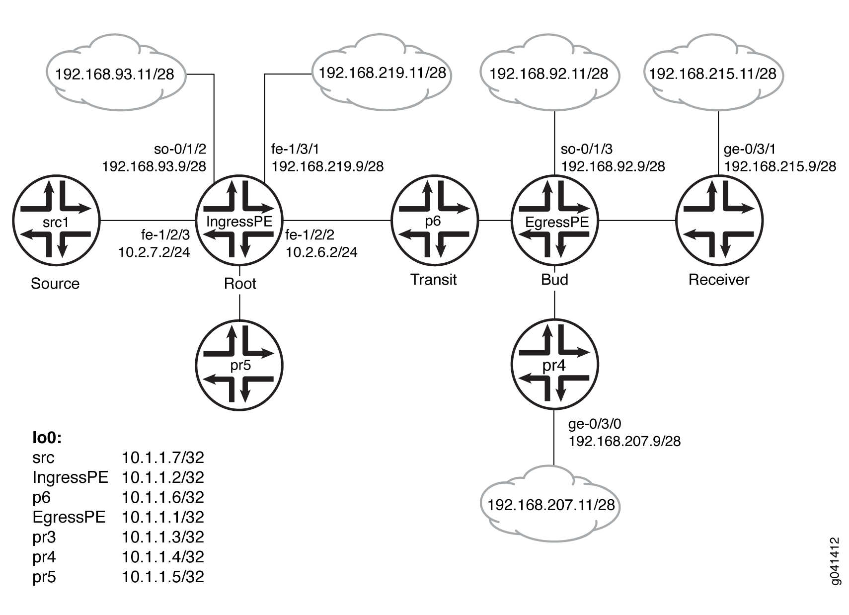
CLI Quick Configuration shows the configuration for all of the devices in Figure 4. The section #d484e113__d484e932 describes the steps on Device EgressPE.
Configuration
Procedure
CLI Quick Configuration
To quickly configure
this example, copy the following commands, paste them into a text
file, remove any line breaks, change any details necessary to match
your network configuration, and then copy and paste the commands into
the CLI at the [edit] hierarchy level.
Device src1
                  set logical-systems src1 interfaces fe-1/2/0 unit 0 family inet address 10.2.7.7/24

                  set logical-systems src1 interfaces lo0 unit 0 family inet address 10.1.1.7/32

                  set logical-systems src1 protocols ospf area 0.0.0.0 interface all
Device IngressPE
                  set interfaces so-0/1/2 unit 0 family inet address 192.168.93.9/28

                  set interfaces fe-1/2/0 unit 0 family inet address 10.2.3.2/24

                  set interfaces fe-1/2/0 unit 0 family mpls

                  set interfaces fe-1/2/1 unit 0 family inet address 10.2.5.2/24

                  set interfaces fe-1/2/2 unit 0 family inet address 10.2.6.2/24

                  set interfaces fe-1/2/2 unit 0 family mpls

                  set interfaces fe-1/2/3 unit 0 family inet address 10.2.7.2/24

                  set interfaces fe-1/3/1 unit 0 family inet address 192.168.219.9/28

                  set interfaces lo0 unit 0 family inet address 10.1.1.2/32

                  set protocols igmp interface fe-1/2/1.0 version 3

                  set protocols igmp interface fe-1/2/1.0 static group 232.1.1.1 source 192.168.219.11

                  set protocols bgp group ibgp type internal

                  set protocols bgp group ibgp local-address 10.1.1.2

                  set protocols bgp group ibgp family inet any

                  set protocols bgp group ibgp family inet-vpn any

                  set protocols bgp group ibgp neighbor 10.1.1.3

                  set protocols bgp group ibgp neighbor 10.1.1.4

                  set protocols bgp group ibgp neighbor 10.1.1.1

                  set protocols ospf area 0.0.0.0 interface all

                  set protocols ldp interface fe-1/2/0.0

                  set protocols ldp interface fe-1/2/2.0

                  set protocols ldp interface lo0.0

                  set protocols ldp p2mp

                  set protocols pim mldp-inband-signalling policy mldppim-ex

                  set protocols pim rp static address 10.1.1.5

                  set protocols pim interface fe-1/3/1.0

                  set protocols pim interface lo0.0

                  set protocols pim interface fe-1/2/0.21

                  set protocols pim interface fe-1/2/3.0

                  set protocols pim interface fe-1/2/1.0

                  set protocols pim interface so-0/1/2.0

                  set policy-options policy-statement mldppim-ex term B from source-address-filter 192.168.0.0/24 orlonger

                  set policy-options policy-statement mldppim-ex term B from source-address-filter 192.168.219.11/32 orlonger

                  set policy-options policy-statement mldppim-ex term B then accept

                  set policy-options policy-statement mldppim-ex term A from source-address-filter 10.1.1.7/32 orlonger

                  set policy-options policy-statement mldppim-ex term A from source-address-filter 10.2.7.0/24 orlonger

                  set policy-options policy-statement mldppim-ex term A then accept

                  set routing-options autonomous-system 64510
Device EgressPE
                  set interfaces so-0/1/3 unit 0 point-to-point

                  set interfaces so-0/1/3 unit 0 family inet address 192.168.92.9/28

                  set interfaces fe-1/2/0 unit 0 family inet address 10.1.3.1/24

                  set interfaces fe-1/2/0 unit 0 family mpls

                  set interfaces fe-1/2/1 unit 0 family inet address 10.1.4.1/24

                  set interfaces fe-1/2/2 unit 0 family inet address 10.1.6.1/24

                  set interfaces fe-1/2/2 unit 0 family mpls

                  set interfaces fe-1/3/0 unit 0 family inet address 192.168.209.9/28

                  set interfaces lo0 unit 0 family inet address 10.1.1.1/32

                  set routing-options autonomous-system 64510

                  set protocols igmp interface fe-1/3/0.0 version 3

                  set protocols igmp interface fe-1/3/0.0 static group 232.1.1.1 group-count 3

                  set protocols igmp interface fe-1/3/0.0 static group 232.1.1.1 source 192.168.219.11

                  set protocols igmp interface fe-1/3/0.0 static group 227.1.1.1

                  set protocols igmp interface so-0/1/3.0 version 3

                  set protocols igmp interface so-0/1/3.0 static group 232.1.1.1 group-count 2

                  set protocols igmp interface so-0/1/3.0 static group 232.1.1.1 source 192.168.219.11

                  set protocols igmp interface so-0/1/3.0 static group 232.2.2.2 source 10.2.7.7

                  set protocols mpls interface fe-1/2/0.0

                  set protocols mpls interface fe-1/2/2.0

                  set protocols bgp group ibgp type internal

                  set protocols bgp group ibgp local-address 10.1.1.1

                  set protocols bgp group ibgp family inet any

                  set protocols bgp group ibgp neighbor 10.1.1.2

                  set protocols msdp local-address 10.1.1.1

                  set protocols msdp peer 10.1.1.5

                  set protocols ospf area 0.0.0.0 interface all

                  set protocols ospf area 0.0.0.0 interface fxp0.0 disable

                  set protocols ldp interface fe-1/2/0.0

                  set protocols ldp interface fe-1/2/2.0

                  set protocols ldp interface lo0.0

                  set protocols ldp p2mp

                  set protocols pim mldp-inband-signalling policy mldppim-ex

                  set protocols pim rp local address 10.1.1.1

                  set protocols pim rp local group-ranges 227.0.0.0/8

                  set protocols pim rp static address 10.1.1.4

                  set protocols pim rp static address 10.2.7.7 group-ranges 226.0.0.0/8

                  set protocols pim interface lo0.0

                  set protocols pim interface fe-1/3/0.0

                  set protocols pim interface fe-1/2/0.0

                  set protocols pim interface fe-1/2/1.0

                  set protocols pim interface so-0/1/3.0

                  set policy-options policy-statement mldppim-ex term B from source-address-filter 192.168.0.0/24 orlonger

                  set policy-options policy-statement mldppim-ex term B from source-address-filter 192.168.219.11/32 orlonger

                  set policy-options policy-statement mldppim-ex term B then p2mp-lsp-root address 10.1.1.2

                  set policy-options policy-statement mldppim-ex term B then accept

                  set policy-options policy-statement mldppim-ex term A from source-address-filter 10.2.7.0/24 orlonger

                  set policy-options policy-statement mldppim-ex term A then accept
Device p6
                  set interfaces fe-1/2/0 unit 0 family inet address 10.1.6.6/24

                  set interfaces fe-1/2/0 unit 0 family mpls

                  set interfaces fe-1/2/1 unit 0 family inet address 10.2.6.6/24

                  set interfaces fe-1/2/1 unit 0 family mpls

                  set interfaces lo0 unit 0 family inet address 10.1.1.6/32

                  set interfaces lo0 unit 0 family mpls

                  set protocols ospf area 0.0.0.0 interface all

                  set protocols ldp interface fe-1/2/0.0

                  set protocols ldp interface fe-1/2/1.0

                  set protocols ldp interface lo0.0

                  set protocols ldp p2mp
Device pr3
                  set interfaces ge-0/3/1 unit 0 family inet address 192.168.215.9/28

                  set interfaces fe-1/2/0 unit 0 family inet address 10.1.3.3/24

                  set interfaces fe-1/2/0 unit 0 family mpls

                  set interfaces fe-1/2/1 unit 0 family inet address 10.2.3.3/24

                  set interfaces fe-1/2/1 unit 0 family mpls

                  set interfaces lo0 unit 0 family inet address 10.1.1.3/32

                  set protocols igmp interface ge-0/3/1.0 version 3

                  set protocols igmp interface ge-0/3/1.0 static group 232.1.1.2 source 192.168.219.11

                  set protocols igmp interface ge-0/3/1.0 static group 232.2.2.2 source 10.2.7.7

                  set protocols bgp group ibgp local-address 10.1.1.3

                  set protocols bgp group ibgp type internal

                  set protocols bgp group ibgp neighbor 10.1.1.2

                  set protocols ospf area 0.0.0.0 interface all

                  set protocols ospf area 0.0.0.0 interface fe-1/2/1.0 metric 2

                  set protocols ldp interface fe-1/2/0.0

                  set protocols ldp interface fe-1/2/1.0

                  set protocols ldp interface lo0.0

                  set protocols ldp p2mp

                  set protocols pim mldp-inband-signalling policy mldppim-ex

                  set protocols pim interface fe-0/3/1.0

                  set protocols pim interface lo0.0

                  set policy-options policy-statement mldppim-ex term B from source-address-filter 192.168.0.0/24 orlonger

                  set policy-options policy-statement mldppim-ex term B from source-address-filter 192.168.219.11/32 orlonger

                  set policy-options policy-statement mldppim-ex term B then p2mp-lsp-root address 10.1.1.2

                  set policy-options policy-statement mldppim-ex term B then accept

                  set policy-options policy-statement mldppim-ex term B from source-address-filter 192.168.0.0/24 orlonger

                  set policy-options policy-statement mldppim-ex term B from source-address-filter 192.168.219.11/32 orlonger

                  set policy-options policy-statement mldppim-ex term B from source-address-filter 10.2.7.7/32 orlonger

                  set policy-options policy-statement mldppim-ex term B then p2mp-lsp-root address 10.1.1.2

                  set policy-options policy-statement mldppim-ex term B then accept

                  set routing-options autonomous-system 64510
Device pr4
                  set interfaces ge-0/3/0 unit 0 family inet address 192.168.207.9/28

                  set interfaces fe-1/2/0 unit 0 family inet address 10.1.4.4/24

                  set interfaces fe-1/2/0 unit 0 family iso

                  set interfaces lo0 unit 0 family inet address 10.1.1.4/32

                  set protocols igmp interface ge-0/3/0.0 version 3

                  set protocols igmp interface ge-0/3/0.0 static group 232.1.1.2 source 192.168.219.11

                  set protocols igmp interface ge-0/3/0.0 static group 225.1.1.1

                  set protocols bgp group ibgp local-address 10.1.1.4

                  set protocols bgp group ibgp type internal

                  set protocols bgp group ibgp neighbor 10.1.1.2

                  set protocols msdp local-address 10.1.1.4

                  set protocols msdp peer 10.1.1.5

                  set protocols ospf area 0.0.0.0 interface all

                  set protocols pim rp local address 10.1.1.4

                  set protocols pim interface ge-0/3/0.0

                  set protocols pim interface lo0.0

                  set protocols pim interface fe-1/2/0.0

                  set routing-options autonomous-system 64510
Device pr5
                  set interfaces fe-1/2/0 unit 0 family inet address 10.2.5.5/24

                  set interfaces lo0 unit 0 family inet address 10.1.1.5/24

                  set protocols igmp interface lo0.0 version 3

                  set protocols igmp interface lo0.0 static group 232.1.1.1 source 192.168.219.11

                  set protocols msdp local-address 10.1.1.5

                  set protocols msdp peer 10.1.1.4

                  set protocols msdp peer 10.1.1.1

                  set protocols ospf area 0.0.0.0 interface all

                  set protocols pim rp local address 10.1.1.5

                  set protocols pim interface all
Step-by-Step Procedure
The following example requires you to navigate various levels in the configuration hierarchy. For information about navigating the CLI, see Using the CLI Editor in Configuration Mode in the CLI User Guide.
To configure Device EgressPE:
-
Configure the interfaces.
Enable MPLS on the core-facing interfaces. On the egress next hops, you do not need to enable MPLS.
[edit interfaces] user@EgressPE# set fe-1/2/0 unit 0 family inet address 10.1.3.1/24 user@EgressPE# set fe-1/2/0 unit 0 family mpls user@EgressPE# set fe-1/2/2 unit 0 family inet address 10.1.6.1/24 user@EgressPE# set fe-1/2/2 unit 0 family mpls user@EgressPE# set so-0/1/3 unit 0 point-to-point user@EgressPE# set so-0/1/3 unit 0 family inet address 192.168.92.9/28 user@EgressPE# set fe-1/2/1 unit 0 family inet address 10.1.4.1/24 user@EgressPE# set fe-1/3/0 unit 0 family inet address 192.168.209.9/28 user@EgressPE# set lo0 unit 0 family inet address 10.1.1.1/32 -
Configure IGMP on the egress interfaces.
For testing purposes, this example includes static group and source addresses.
[edit protocols igmp] user@EgressPE# set interface fe-1/3/0.0 version 3 user@EgressPE# set interface fe-1/3/0.0 static group 232.1.1.1 group-count 3 user@EgressPE# set interface fe-1/3/0.0 static group 232.1.1.1 source 192.168.219.11 user@EgressPE# set interface fe-1/3/0.0 static group 227.1.1.1 user@EgressPE# set interface so-0/1/3.0 version 3 user@EgressPE# set interface so-0/1/3.0 static group 232.1.1.1 group-count 2 user@EgressPE# set interface so-0/1/3.0 static group 232.1.1.1 source 192.168.219.11 user@EgressPE# set interface so-0/1/3.0 static group 232.2.2.2 source 10.2.7.7 -
Configure MPLS on the core-facing interfaces.
[edit protocols mpls] user@EgressPE# set interface fe-1/2/0.0 user@EgressPE# set interface fe-1/2/2.0 -
Configure BGP.
BGP is a policy-driven protocol, so also configure and apply any needed routing policies.
For example, you might want to export static routes into BGP.
[edit protocols bgp group ibgp] user@EgressPE# set type internal user@EgressPE# set local-address 10.1.1.1 user@EgressPE# set family inet any user@EgressPE# set neighbor 10.1.1.2 -
(Optional) Configure an MSDP peer connection with Device pr5 in order to interconnect the disparate PIM domains, thus enabling redundant RPs.
[edit protocols msdp] user@EgressPE# set local-address 10.1.1.1 user@EgressPE# set peer 10.1.1.5 -
Configure OSPF.
[edit protocols ospf area 0.0.0.0] user@EgressPE# set interface all user@EgressPE# set interface fxp0.0 disable -
Configure LDP on the core-facing interfaces and on the loopback interface.
[edit protocols ldp] user@EgressPE# set interface fe-1/2/0.0 user@EgressPE# set interface fe-1/2/2.0 user@EgressPE# set interface lo0.0 -
Enable point-to-multipoint MPLS LSPs.
[edit protocols ldp] user@EgressPE# set p2mp -
Configure PIM on the downstream interfaces.
[edit protocols pim] user@EgressPE# set interface lo0.0 user@EgressPE# set interface fe-1/3/0.0 user@EgressPE# set interface fe-1/2/1.0 user@EgressPE# set interface so-0/1/3.0 -
Configure the RP settings because this device serves as the PIM rendezvous point (RP).
[edit protocols pim] user@EgressPE# set rp local address 10.1.1.1 user@EgressPE# set rp local group-ranges 227.0.0.0/8 user@EgressPE# set rp static address 10.1.1.4 user@EgressPE# set rp static address 10.2.7.7 group-ranges 226.0.0.0/8 -
Enable M-LDP in-band signaling and set the associated policy.
[edit protocols pim] user@EgressPE# set mldp-inband-signalling policy mldppim-ex -
Configure the routing policy that specifies the root address for the point-to-multipoint LSP and the associated source addresses.
[edit policy-options policy-statement mldppim-ex] user@EgressPE# set term B from source-address-filter 192.168.0.0/24 orlonger user@EgressPE# set term B from source-address-filter 192.168.219.11/32 orlonger user@EgressPE# set term B then p2mp-lsp-root address 10.1.1.2 user@EgressPE# set term B then accept user@EgressPE# set term A from source-address-filter 10.2.7.0/24 orlonger user@EgressPE# set term A then accept -
Configure the autonomous system (AS) ID.
[edit routing-options]
user@EgressPE# set autonomous-system 64510
Results
From configuration mode, confirm your configuration
by entering the show interfaces, show protocols, show policy-options, and show routing-options commands. If the output does not display the intended configuration,
repeat the instructions in this example to correct the configuration.
Device EgressPE
user@EgressPE#
                     show interfaces

so-0/1/3 {
    unit 0 {
        point-to-point;
        family inet {
            address 192.168.92.9/28;
        }
    }
}
fe-1/2/0 {
    unit 0 {
        family inet {
            address 10.1.3.1/24;
        }
        family mpls;
    }
}
fe-1/2/1 {
    unit 0 {
        family inet {
            address 10.1.4.1/24;
        }
    }
}
fe-1/2/2 {
    unit 0 {
        family inet {
            address 10.1.6.1/24;
        }
        family mpls;
    }
}
fe-1/3/0 {
    unit 0 {
        family inet {
            address 192.168.209.9/28;
        }
    }
}
lo0 {
    unit 0 {
        family inet {
            address 10.1.1.1/32;
        }
    }
}
user@EgressPE#
                     show protocols

igmp {
    interface fe-1/3/0.0 {
        version 3;
        static {
            group 232.1.1.1 {
                group-count 3;
                source 192.168.219.11;
            }
            group 227.1.1.1;
        }
    }
    interface so-0/1/3.0 {
        version 3;
        static {
            group 232.1.1.1 {
                group-count 2;
                source 192.168.219.11;
            }
            group 232.2.2.2 {
                source 10.2.7.7;
            }
        }
    }
}
mpls {
    interface fe-1/2/0.0;
    interface fe-1/2/2.0;
}
bgp {
    group ibgp {
        type internal;
        local-address 10.1.1.1;
        family inet {
            any;
        }
        neighbor 10.1.1.2;
    }
}
msdp {
    local-address 10.1.1.1;
    peer 10.1.1.5;
}
ospf {
    area 0.0.0.0 {
        interface all;
        interface fxp0.0 {
            disable;
        }
    }
}
ldp {
    interface fe-1/2/0.0;
    interface fe-1/2/2.0;
    interface lo0.0;
    p2mp;
}
pim {
    mldp-inband-signalling {
        policy mldppim-ex;
    }
    rp {
        local {
            address 10.1.1.1;
            group-ranges {
                227.0.0.0/8;
            }
        }
        static {
            address 10.1.1.4;
            address 10.2.7.7 {
                group-ranges {
                    226.0.0.0/8;
                }
            }
        }
    }
    interface lo0.0;
    interface fe-1/3/0.0;
    interface fe-1/2/0.0;
    interface fe-1/2/1.0;
    interface so-0/1/3.0;
}
user@EgressPE#
                     show policy-options

policy-statement mldppim-ex {
    term B {
        from {
            source-address-filter 192.168.0.0/24 orlonger;
            source-address-filter 192.168.219.11/32 orlonger;
        }
        then {
            p2mp-lsp-root {
                address 10.1.1.2;
            }
            accept;
        }
    }
    term A {
        from {
            source-address-filter 10.2.7.0/24 orlonger;
        }
        then accept;
    }
}
user@EgressPE#
                     show routing-options

autonomous-system 64510;
Similarly, configure the other egress devices.
If you are done configuring the devices, enter commit from configuration mode.
Verification
Confirm that the configuration is working properly.
- Checking the PIM Join States
- Checking the PIM Sources
- Checking the LDP Database
- Looking Up the Route Information for the MPLS Label
- Checking the LDP Traffic Statistics
Checking the PIM Join States
Purpose
Display information about PIM join states to verify
the M-LDP in-band upstream and downstream details. On the ingress
device, the show pim join extensive command displays Pseudo-MLDP for the downstream interface. On the
egress, the show pim join extensive command displays Pseudo-MLDP for the upstream interface.
Action
From operational mode, enter the show pim join
extensive command.
user@IngressPE> show pim join extensive

Instance: PIM.master Family: INET
R = Rendezvous Point Tree, S = Sparse, W = Wildcard

Group: 232.1.1.1
    Source: 192.168.219.11
    Flags: sparse,spt
    Upstream interface: fe-1/3/1.0
    Upstream neighbor: Direct
    Upstream state: Local Source
    Keepalive timeout:
    Uptime: 1d 23:00:12
    Downstream neighbors:
        Interface: Pseudo-MLDP
        Interface: fe-1/2/1.0
            10.2.5.2 State: Join Flags: S   Timeout: Infinity
            Uptime: 1d 23:00:12 Time since last Join: 1d 23:00:12

Group: 232.1.1.2
    Source: 192.168.219.11
    Flags: sparse,spt
    Upstream interface: fe-1/3/1.0
    Upstream neighbor: Direct
    Upstream state: Local Source
    Keepalive timeout:
    Uptime: 1d 22:59:59
    Downstream neighbors:
        Interface: Pseudo-MLDP

Group: 232.1.1.3
    Source: 192.168.219.11
    Flags: sparse,spt
    Upstream interface: fe-1/3/1.0
    Upstream neighbor: Direct
    Upstream state: Local Source
    Keepalive timeout:
    Uptime: 1d 22:07:31
    Downstream neighbors:
        Interface: Pseudo-MLDP

Group: 232.2.2.2
    Source: 10.2.7.7
    Flags: sparse,spt
    Upstream interface: fe-1/2/3.0
    Upstream neighbor: Direct
    Upstream state: Local Source
    Keepalive timeout:
    Uptime: 1d 22:59:59
    Downstream neighbors:
        Interface: Pseudo-MLDP


user@EgressPE> show pim join extensive

Instance: PIM.master Family: INET
R = Rendezvous Point Tree, S = Sparse, W = Wildcard

Group: 227.1.1.1
    Source: *
    RP: 10.1.1.1
    Flags: sparse,rptree,wildcard
    Upstream interface: Local
    Upstream neighbor: Local
    Upstream state: Local RP
    Uptime: 1d 23:14:21
    Downstream neighbors:
        Interface: fe-1/3/0.0
            192.168.209.9 State: Join Flags: SRW  Timeout: Infinity
            Uptime: 1d 23:14:21 Time since last Join: 1d 20:12:35

Group: 232.1.1.1
    Source: 192.168.219.11
    Flags: sparse,spt
    Upstream protocol: MLDP
    Upstream interface: Pseudo MLDP
    Upstream neighbor: MLDP LSP root <10.1.1.2>
    Upstream state: Join to Source
    Keepalive timeout:
    Uptime: 1d 23:14:22
    Downstream neighbors:
        Interface: so-0/1/3.0
            192.168.92.9 State: Join Flags: S   Timeout: Infinity
            Uptime: 1d 20:12:35 Time since last Join: 1d 20:12:35
    Downstream neighbors:
        Interface: fe-1/3/0.0
            192.168.209.9 State: Join Flags: S   Timeout: Infinity
            Uptime: 1d 20:12:35 Time since last Join: 1d 20:12:35

Group: 232.1.1.2
    Source: 192.168.219.11
    Flags: sparse,spt
    Upstream protocol: MLDP
    Upstream interface: Pseudo MLDP
    Upstream neighbor: MLDP LSP root <10.1.1.2>
    Upstream state: Join to Source
    Keepalive timeout:
    Uptime: 1d 23:14:22
    Downstream neighbors:
        Interface: so-0/1/3.0
            192.168.92.9 State: Join Flags: S   Timeout: Infinity
            Uptime: 1d 20:12:35 Time since last Join: 1d 20:12:35
    Downstream neighbors:
        Interface: fe-1/2/1.0
            10.1.4.4 State: Join Flags: S Timeout: 198
            Uptime: 1d 22:59:59 Time since last Join: 00:00:12
    Downstream neighbors:
        Interface: fe-1/3/0.0
            192.168.209.9 State: Join Flags: S   Timeout: Infinity
            Uptime: 1d 20:12:35 Time since last Join: 1d 20:12:35

Group: 232.1.1.3
    Source: 192.168.219.11
    Flags: sparse,spt
    Upstream protocol: MLDP
    Upstream interface: Pseudo MLDP
    Upstream neighbor: MLDP LSP root <10.1.1.2>
    Upstream state: Join to Source
    Keepalive timeout:
    Uptime: 1d 20:12:35
    Downstream neighbors:
        Interface: fe-1/3/0.0
            192.168.209.9 State: Join Flags: S   Timeout: Infinity
            Uptime: 1d 20:12:35 Time since last Join: 1d 20:12:35

Group: 232.2.2.2
    Source: 10.2.7.7
    Flags: sparse,spt
    Upstream protocol: MLDP
    Upstream interface: Pseudo MLDP
    Upstream neighbor: MLDP LSP root <10.1.1.2>
    Upstream state: Join to Source
    Keepalive timeout:
    Uptime: 1d 20:12:35
    Downstream neighbors:
        Interface: so-0/1/3.0
            192.168.92.9 State: Join Flags: S   Timeout: Infinity
            Uptime: 1d 20:12:35 Time since last Join: 1d 20:12:35

user@pr3> show pim join extensive

Instance: PIM.master Family: INET
R = Rendezvous Point Tree, S = Sparse, W = Wildcard

Group: 232.1.1.2
    Source: 192.168.219.11
    Flags: sparse,spt
    Upstream protocol: MLDP
    Upstream interface: Pseudo MLDP

                  Upstream neighbor: MLDP LSP root <10.1.1.2>
    Upstream state: Join to Source
    Keepalive timeout:
    Uptime: 1d 20:14:40
    Downstream neighbors:
        Interface: Pseudo-GMP
            ge-0/3/1.0

Group: 232.2.2.2
    Source: 10.2.7.7
    Flags: sparse,spt
    Upstream protocol: MLDP
    Upstream interface: Pseudo MLDP
    Upstream neighbor: MLDP LSP root <10.1.1.2>
    Upstream state: Join to Source
    Keepalive timeout:
    Uptime: 1d 20:14:40
    Downstream neighbors:
        Interface: Pseudo-GMP
            ge-0/3/1.0


user@pr4> show pim join extensive
Instance: PIM.master Family: INET
R = Rendezvous Point Tree, S = Sparse, W = Wildcard

Group: 225.1.1.1
    Source: *
    RP: 10.1.1.4
    Flags: sparse,rptree,wildcard
    Upstream interface: Local
    Upstream neighbor: Local
    Upstream state: Local RP
    Uptime: 1d 23:13:43
    Downstream neighbors:
        Interface: ge-0/3/0.0
            192.168.207.9 State: Join Flags: SRW  Timeout: Infinity
            Uptime: 1d 23:13:43 Time since last Join: 1d 23:13:43

Group: 232.1.1.2
    Source: 192.168.219.11
    Flags: sparse,spt
    Upstream interface: fe-1/2/0.0
    Upstream neighbor: 10.1.4.1
    Upstream state: Local RP, Join to Source
    Keepalive timeout: 0
    Uptime: 1d 23:13:43
    Downstream neighbors:
        Interface: ge-0/3/0.0
            192.168.207.9 State: Join Flags: S   Timeout: Infinity
            Uptime: 1d 23:13:43 Time since last Join: 1d 23:13:43


user@pr5> show pim join extensive
            ge-0/3/1.0

Instance: PIM.master Family: INET
R = Rendezvous Point Tree, S = Sparse, W = Wildcard

Instance: PIM.master Family: INET6
R = Rendezvous Point Tree, S = Sparse, W = Wildcard
Checking the PIM Sources
Purpose
Verify that the PIM sources have the expected M-LDP in-band upstream and downstream details.
Action
From operational mode, enter the show pim source command.
user@IngressPE> show pim source

Instance: PIM.master Family: INET

Source 10.1.1.1
    Prefix 10.1.1.1/32
    Upstream interface Local
    Upstream neighbor Local

Source 10.2.7.7
    Prefix 10.2.7.0/24
    Upstream protocol MLDP
    Upstream interface Pseudo MLDP
    Upstream neighbor MLDP LSP root <10.1.1.2>

Source 192.168.219.11
    Prefix 192.168.219.0/28
    Upstream protocol MLDP
    Upstream interface Pseudo MLDP
    Upstream neighbor MLDP LSP root <10.1.1.2>
user@EgressPE> show pim source
Instance: PIM.master Family: INET

Source 10.2.7.7
    Prefix 1.2.7.0/24
    Upstream interface fe-1/2/3.0
    Upstream neighbor 10.2.7.2

Source 10.2.7.7
    Prefix 10.2.7.0/24
    Upstream interface fe-1/2/3.0
    Upstream neighbor Direct

Source 192.168.219.11
    Prefix 192.168.219.0/28
    Upstream interface fe-1/3/1.0
    Upstream neighbor 192.168.219.9

Source 192.168.219.11
    Prefix 192.168.219.0/28
    Upstream interface fe-1/3/1.0
    Upstream neighbor Direct
user@pr3> show pim source

Instance: PIM.master Family: INET

Source 10.2.7.7
    Prefix 1.2.7.0/24
    Upstream protocol MLDP
    Upstream interface Pseudo MLDP
    Upstream neighbor MLDP LSP root <10.1.1.2>

Source 192.168.219.11
    Prefix 192.168.219.0/28
    Upstream protocol MLDP
    Upstream interface Pseudo MLDP
    Upstream neighbor MLDP LSP root <10.1.1.2>
user@pr4> show pim source
Instance: PIM.master Family: INET

Source 10.1.1.4
    Prefix 10.1.1.4/32
    Upstream interface Local
    Upstream neighbor Local

Source 192.168.219.11
    Prefix 192.168.219.0/28
    Upstream interface fe-1/2/0.0
    Upstream neighbor 10.1.4.1
Checking the LDP Database
Purpose
Make sure that the
show ldp database
command displays the expected
root-to-(S,G) bindings.
Action
user@IngressPE> show ldp database
Input label database, 10.255.2.227:0--10.1.1.3:0
  Label     Prefix
 300096      10.1.1.2/32
      3      10.1.1.3/32
 299856      10.1.1.6/32
 299776      10.255.2.227/32

Output label database, 10.255.2.227:0--10.1.1.3:0
  Label     Prefix
 300144      10.1.1.2/32
 299776      10.1.1.3/32
 299856      10.1.1.6/32
      3      10.255.2.227/32

Input label database, 10.255.2.227:0--10.1.1.6:0
  Label     Prefix
 299936      10.1.1.2/32
 299792      10.1.1.3/32
      3      10.1.1.6/32
 299776      10.255.2.227/32

Output label database, 10.255.2.227:0--10.1.1.6:0
  Label     Prefix
 300144      10.1.1.2/32
 299776      10.1.1.3/32
 299856      10.1.1.6/32
      3      10.255.2.227/32
 300432      P2MP root-addr 10.1.1.2, grp: 232.2.2.2, src: 10.2.7.7
 300288      P2MP root-addr 10.1.1.2, grp: 232.1.1.1, src: 192.168.219.11
 300160      P2MP root-addr 10.1.1.2, grp: 232.1.1.2, src: 192.168.219.11
 300480      P2MP root-addr 10.1.1.2, grp: 232.1.1.3, src: 192.168.219.11
user@EgressPE> show ldp database

Input label database, 10.1.1.2:0--10.1.1.3:0
  Label     Prefix
 300096      10.1.1.2/32
      3      10.1.1.3/32
 299856      10.1.1.6/32
 299776      10.255.2.227/32
 300144      P2MP root-addr 10.1.1.2, grp: 232.2.2.2, src: 10.2.7.7
 300128      P2MP root-addr 10.1.1.2, grp: 232.1.1.2, src: 192.168.219.11

Output label database, 10.1.1.2:0--10.1.1.3:0
  Label     Prefix
      3      10.1.1.2/32
 299776      10.1.1.3/32
 299808      10.1.1.6/32
 299792      10.255.2.227/32

Input label database, 10.1.1.2:0--10.1.1.6:0
  Label     Prefix
 299936      10.1.1.2/32
 299792      10.1.1.3/32
      3      10.1.1.6/32
 299776      10.255.2.227/32
 300128      P2MP root-addr 10.1.1.2, grp: 232.2.2.2, src: 10.2.7.7
 299984      P2MP root-addr 10.1.1.2, grp: 232.1.1.1, src: 192.168.219.11
 299952      P2MP root-addr 10.1.1.2, grp: 232.1.1.2, src: 192.168.219.11
 300176      P2MP root-addr 10.1.1.2, grp: 232.1.1.3, src: 192.168.219.11
 300192      P2MP root-addr 10.1.1.2, grp: ff3e::1:2, src: 2001:db8:abcd::10:2:7:7

Output label database, 10.1.1.2:0--10.1.1.6:0
  Label     Prefix
      3      10.1.1.2/32
 299776      10.1.1.3/32
 299808      10.1.1.6/32
 299792      10.255.2.227/32
-----

logical-system: default

Input label database, 10.255.2.227:0--10.1.1.3:0
  Label     Prefix
 300096      10.1.1.2/32
      3      10.1.1.3/32
 299856      10.1.1.6/32
 299776      10.255.2.227/32

Output label database, 10.255.2.227:0--10.1.1.3:0
  Label     Prefix
 300144      10.1.1.2/32
 299776      10.1.1.3/32
 299856      10.1.1.6/32
      3      10.255.2.227/32

Input label database, 10.255.2.227:0--10.1.1.6:0
  Label     Prefix
 299936      10.1.1.2/32
 299792      10.1.1.3/32
      3      10.1.1.6/32
 299776      10.255.2.227/32

Output label database, 10.255.2.227:0--10.1.1.6:0
  Label     Prefix
 300144      10.1.1.2/32
 299776      10.1.1.3/32
 299856      10.1.1.6/32
      3      10.255.2.227/32
 300432      P2MP root-addr 10.1.1.2, grp: 232.2.2.2, src: 10.2.7.7
 300288      P2MP root-addr 10.1.1.2, grp: 232.1.1.1, src: 192.168.219.11
 300160      P2MP root-addr 10.1.1.2, grp: 232.1.1.2, src: 192.168.219.11
 300480      P2MP root-addr 10.1.1.2, grp: 232.1.1.3, src: 192.168.219.11
 300496      P2MP root-addr 10.1.1.2, grp: ff3e::1:2, src: 2001:db8:abcd::10:2:7:7
user@p6> show ldp database

Input label database, 10.1.1.6:0--10.1.1.2:0
  Label     Prefix
      3      10.1.1.2/32
 299776      10.1.1.3/32
 299808      10.1.1.6/32

Output label database, 10.1.1.6:0--10.1.1.2:0
  Label     Prefix
 299776      10.1.1.2/32
 299792      10.1.1.3/32
3 10.1.1.6/32user@pr3> show ldp database
Input label database, 10.1.1.3:0--10.1.1.2:0
Label Prefix
3 10.1.1.2/32
299776 10.1.1.3/32
299808 10.1.1.6/32
299792 10.255.2.227/32
Output label database, 10.1.1.3:0--10.1.1.2:0
Label Prefix
300096 10.1.1.2/32
3 10.1.1.3/32
299856 10.1.1.6/32
299776 10.255.2.227/32
300144 P2MP root-addr 10.1.1.2, grp: 232.2.2.2, src: 10.2.7.7
300128 P2MP root-addr 10.1.1.2, grp: 232.1.1.2, src: 192.168.219.11
Input label database, 10.1.1.3:0--10.255.2.227:0
Label Prefix
300144 10.1.1.2/32
299776 10.1.1.3/32
299856 10.1.1.6/32
3 10.255.2.227/32
Output label database, 10.1.1.3:0--10.255.2.227:0
Label Prefix
300096 10.1.1.2/32
3 10.1.1.3/32
299856 10.1.1.6/32
299776 10.255.2.227/32
Looking Up the Route Information for the MPLS Label
Purpose
Display the point-to-multipoint FEC information.
Action
user@EgressPE> show route label 299808 detail

mpls.0: 14 destinations, 14 routes (14 active, 0 holddown, 0 hidden)
299808 (1 entry, 1 announced)
        *LDP    Preference: 9
                Next hop type: Flood
                Address: 0x931922c
                Next-hop reference count: 3
                Next hop type: Router, Next hop index: 1109
                Address: 0x9318b0c
                Next-hop reference count: 2
                Next hop: via so-0/1/3.0
                Label operation: Pop
                Next hop type: Router, Next hop index: 1110
                Address: 0x93191e0
                Next-hop reference count: 2
                Next hop: 192.168.209.11 via fe-1/3/0.0
                Label operation: Pop
                State: **Active Int AckRequest>
                Local AS:    10
                Age: 13:08:15   Metric: 1
                Validation State: unverified
                Task: LDP
                Announcement bits (1): 0-KRT
                AS path: I
                FECs bound to route: P2MP root-addr 10.1.1.2, grp: 232.1.1.1, src: 192.168.219.11
Checking the LDP Traffic Statistics
Purpose
Monitor the data traffic statistics for the point-to-multipoint LSP.
Action
user@EgressPE> show ldp traffic-statistics p2mp
P2MP FEC Statistics:

FEC(root_addr:lsp_id/grp,src)     Nexthop              Packets             Bytes Shared
10.1.1.2:232.2.2.2,10.2.7.7         so-0/1/3.0                 0                 0 No
10.1.1.2:232.1.1.1,192.168.219.11  so-0/1/3.0                 0                 0 No
                                  fe-1/3/0.0                 0                 0 No
10.1.1.2:232.1.1.2,192.168.219.11  so-0/1/3.0                 0                 0 No
                                  fe-1/3/0.0                 0                 0 No
                                  lt-1/2/0.14                0                 0 No
10.1.1.2:232.1.1.3,192.168.219.11  fe-1/3/0.0                 0                 0 No
10.1.1.2:ff3e::1:2,2001:db8:abcd::1:2:7:7   fe-1/3/0.0                 0                 0 No
Change History Table
Feature support is determined by the platform and release you are using. Use Feature Explorer to determine if a feature is supported on your platform.