ON THIS PAGE
GMPLS Configuration
Introduction to GMPLS
Traditional MPLS is designed to carry Layer 3 IP traffic using established IP-based paths and associating these paths with arbitrarily assigned labels. These labels can be configured explicitly by a network administrator, or can be dynamically assigned by means of a protocol such as LDP or RSVP.
GMPLS generalizes MPLS in that it defines labels for switching varying types of Layer 1, Layer 2, or Layer 3 traffic. GMPLS nodes can have links with one or more of the following switching capabilities:
Fiber-switched capable (FSC)
Lambda-switched capable (LSC)
Time-division multiplexing (TDM) switched-capable (TSC)
Packet-switched capable (PSC)
Label-switched paths (LSPs) must start and end on links with the same switching capability. For example, routers can establish packet-switched LSPs with other routers. The LSPs might be carried over a TDM-switched LSP between SONET add/drop multiplexers (ADMs), which in turn might be carried over a lambda-switched LSP.
The result of this extension of the MPLS protocol is an expansion in the number of devices that can participate in label switching. Lower-layer devices, such as OXCs and SONET ADMs, can now participate in GMPLS signaling and set up paths to transfer data. A router can participate in signaling optical paths across a transport network.
Two service models determine the visibility that a client node (a router, for example) has into the optical core or transport network. The first is through a user-to-network interface (UNI), which is often referred to as the overlay model. The second is known as the peer model. Juniper Networks supports both models.
There is not necessarily a one-to-one correspondence between a physical interface and a GMPLS interface. If a GMPLS connection uses a nonchannelized physical connector, the GMPLS label can use the physical port ID. However, the label for channelized interfaces often is based on a channel or time slot. Consequently, it is best to refer to GMPLS labels as identifiers for a resource on a traffic engineering link.
To establish LSPs, GMPLS uses the following mechanisms:
An out-of-band control channel and a data channel—RSVP messages for LSP setup are sent over an out-of-band control network. Once the LSP setup is complete and the path is provisioned, the data channel is up and can be used to carry traffic. The Link Management Protocol (LMP) is used to define and manage the data channels between a pair of nodes. You can optionally use LMP to establish and maintain LMP control channels between peers running the same Junos OS Release.
RSVP-TE extensions for GMPLS—RSVP-TE is already designed to signal the setup of packet LSPs. This has been extended for GMPLS to be able to request path setup for various kinds of LSPs (nonpacket) and request labels like wavelengths, time slots, and fibers as label objects.
Bidirectional LSPs—Data can travel both ways between GMPLS devices over a single path, so nonpacket LSPs are signaled to be bidirectional.
GMPLS Terms and Acronyms
Generalized MPLS (GMPLS)
An extension to MPLS that allows data from multiple layers to be switched over label-switched paths (LSPs). GMPLS LSP connections are possible between similar Layer 1, Layer 2, and Layer 3 devices.
Forwarding adjacency
A forwarding path for sending data between GMPLS-enabled devices.
GMPLS label
Layer 3 identifiers, fiber port, time-division multiplexing (TDM) time slot, or dense wavelength-division multiplexing (DWDM) wavelength of a GMPLS-enabled device used as a next-hop identifier.
GMPLS LSP types
The four types of GMPLS LSPs are:
Fiber-switched capable (FSC)—LSPs are switched between two fiber-based devices, such optical cross-connects (OXCs) that operate at the level of individual fibers.
Lambda-switched capable (LSC)—LSPs are switched between two DWDM devices, such as such as OXCs that operate at the level of individual wavelengths.
TDM-switched capable (TDM)—LSPs are switched between two TDM devices, such as SONET ADMs.
Packet-switched capable (PSC)—LSPs are switched between two packet-based devices, such as routers or ATM switches.
Link Management Protocol
A protocol used to define a forwarding adjacency between peers and to maintain and allocate resources on the traffic engineering links.
Traffic engineering link
A logical connection between GMPLS-enabled devices. Traffic engineering links can have addresses or IDs and are associated with certain resources or interfaces. They also have certain attributes (encoding-type, switching capability, bandwidth, and so on). The logical addresses can be routable, although this is not required because they are acting as link identifiers. Each traffic engineering link represents a forwarding adjacency between a pair of devices.
GMPLS Operation
The basic functionality of GMPLS requires close interaction between RSVP and LMP. It works in the following sequence:
LMP notifies RSVP of the new entities:
Traffic engineering link (forwarding adjacency)
Resources available for the traffic engineering link
Control peer
GMPLS extracts the LSP attributes from the configuration and requests RSVP to signal one or more specific paths, which are specified by the traffic engineering link addresses.
RSVP determines the local traffic engineering link, corresponding control adjacency and active control channel, and transmission parameters (such as IP destination). It requests that LMP allocate a resource from the traffic engineering link with the specified attributes. If LMP finds a resource matching the attributes, label allocation succeeds. RSVP sends a PathMsg hop by hop until it reaches the target router.
When the target router receives the PathMsg, RSVP again requests that LMP allocate a resource based on the signaled parameters. If label allocation succeeds, the router sends back a ResvMsg.
If the signaling is successful, a bidirectional optical path is provisioned.
GMPLS and OSPF
You can configure OSPF for GMPLS. OSPF is an interior gateway protocol (IGP) that routes packets within a single autonomous system (AS). OSPF uses link-state information to make routing decisions.
GMPLS and CSPF
GMPLS introduces extra constraints for computing paths for GMPLS LSPs that use CSPF. These additional constraints affect the following link attributes:
Signal type (minimum LSP bandwidth)
Encoding type
Switching type
These new constraints are populated in the traffic engineering database with the exchange of an interface-switching capability descriptor type, length, value (TLV) through an IGP.
The ignored constraints that are exchanged through the interface switching capability descriptor include:
Maximum LSP bandwidth
Maximum transmission unit (MTU)
The CSPF path computation is the same as in non-GMPLS environments, except that the links are also limited by GMPLS constraints.
Each link can have multiple interface-switching capability descriptors. All the descriptors are checked before a link is rejected.
The constraints are checked in the following order:
The signal type configured for the GMPLS LSP signifies the amount of bandwidth requested. If the desired bandwidth is less than the minimum LSP bandwidth, the interface-switching descriptor is rejected.
The encoding type of the link for the ingress and the egress interfaces should match. The encoding type is selected and stored at the ingress node after all the constraints are satisfied by the link and is used to select the link on the egress node.
The switching type of the links of the intermediate switches should match that of the GMPLS LSP specified in the configuration.
GMPLS Features
The Junos OS includes the following GMPLS functionality:
An out-of-band control plane makes it possible to signal LSP path setup.
RSVP-TE extensions support additional objects beyond Layer 3 packets, such as ports, time slots, and wavelengths.
The LMP protocol creates and maintains a database of traffic engineering links and peer information. Only the static version of this protocol is supported in the Junos OS. You can optionally configure LMP to establish and maintain LMP control channels between peers running the same Junos OS Release.
Bidirectional LSPs are required between devices.
Several GMPLS label types that are defined in RFC 3471, Generalized MPLS—Signaling Functional Description, such as MPLS, Generalized, SONET/SDH, Suggested, and Upstream, are supported. Generalized labels do not contain a type field, because the nodes should know from the context of their connection what type of label to expect.
Traffic parameters facilitate GMPLS bandwidth encoding and SONET/SDH formatting.
Other supported attributes include interface identification and errored interface identification, user-to-network (UNI)-style signaling, and secondary LSP paths.
Configuring MPLS Paths for GMPLS
As part of the configuration for GMPLS, you need to establish
an MPLS path for each unique device connected through GMPLS. Configure
the traffic engineering link remote address as the address at the [edit protocols mpls path path-name] hierarchy
level. Constrained Shortest Path First (CSPF) is supported so you
can choose either the strict or loose option
with the address.
See LMP Configuration Overview for information about how to obtain a traffic engineering link remote address.
To configure the MPLS path, include the path statement
at the [edit protocols mpls] hierarchy level:
[edit protocols mpls]
path path-name {
    next-hop-address (strict | loose);
}
For information about how to configure MPLS paths, see Creating Named Paths.
Tracing LMP Traffic
To trace LMP protocol traffic, include the traceoptions statement at the [edit protocols link-management] hierarchy
level:
[edit protocols link-management]
traceoptions {
    file filename <files number> <size size> <world-readable | no-world-readable>;
    flag flag <flag-modifier> <disable>;
}
Use the file statement to specify the name of the
file that receives the output of the tracing operation. All files
are placed in the directory /var/log.
The following trace flags display the operations associated with the sending and receiving of various LMP messages:
all—Trace all available operationshello-packets—Trace hello packets on any LMP control channelinit—Output from the initialization messagespackets—Trace all packets other than hello packets on any LMP control channelparse—Operation of the parserprocess—Operation of the general configurationroute-socket—Operation of route socket eventsrouting—Operation of the routing protocolsserver—Server processing operationsshow—Servicing operations forshowcommandsstate—Trace state transitions of the LMP control channels and traffic engineering links
Each flag can carry one or more of the following flag modifiers:
detail—Provide detailed trace informationreceive—Packets being receivedsend—Packets being transmitted
Configuring MPLS LSPs for GMPLS
To enable the proper GMPLS switching parameters, configure the
label-switched path (LSP) attributes that are appropriate for your
network connection. The default value for switching-type is psc-1, which is also appropriate for standard MPLS.
To configure the LSP attributes, include the lsp-attributes statement at the [edit protocols mpls label-switched-path lsp-name] hierarchy level:
[edit protocols mpls label-switched-path lsp-name]
lsp-attributes {
    encoding-type type;
    gpid gpid;
    signal-bandwidth type;
    switching-type type;
}
If you include the no-cspf statement in the label-switched
path configuration, you must also configure primary and secondary
paths, or the configuration cannot be committed.
The following sections describe how to configure each of the LSP attributes for a GMPLS LSP:
- Configuring the Encoding Type
- Configuring the GPID
- Configuring the Signal Bandwidth Type
- Configuring GMPLS Bidirectional LSPs
- Allowing Nonpacket GMPLS LSPs to Establish Paths Through Routers Running Junos OS
Configuring the Encoding Type
You need to specify the encoding type of the payload carried by the LSP. It can be any of the following:
ethernet—Ethernetpacket—Packetpdh—Plesiochronous digital hierarchy (PDH)sonet-sdh—SONET/SDH
The default value is packet.
To configure the encoding type, include the encoding-type statement at the [edit protocols mpls label-switched-path lsp-name lsp-attributes] hierarchy level:
[edit protocols mpls label-switched-path lsp-name lsp-attributes]
encoding-type type;
Configuring the GPID
You need to specify the type of payload carried by the LSP. The payload is the type of packet underneath the MPLS label. The payload is specified by the generalized payload identifier (GPID).
You can specify the GPID with any of the following values:
hdlc—High-Level Data Link Control (HDLC)ethernet—Ethernetipv4—IP version 4 (default)pos-scrambling-crc-16—For interoperability with other vendors’ equipmentpos-no-scrambling-crc-16—For interoperability with other vendors’ equipmentpos-scrambling-crc-32—For interoperability with other vendors’ equipmentpos-no-scrambling-crc-32—For interoperability with other vendors’ equipmentppp—Point-to-Point Protocol (PPP)
To configure the GPID, include the gpid statement
at the [edit protocols mpls label-switched-path lsp-name lsp-attributes] hierarchy level:
[edit protocols mpls label-switched-path lsp-name lsp-attributes]
gpid gpid;
Configuring the Signal Bandwidth Type
The signal bandwidth type is the encoding used for path computation
and admission control. To configure the signal bandwidth type, include
the signal-bandwidth statement at the [edit protocols
mpls label-switched-path lsp-name lsp-attributes] hierarchy level:
[edit protocols mpls label-switched-path lsp-name lsp-attributes] signal-bandwidth type;
Configuring GMPLS Bidirectional LSPs
Because MPLS and GMPLS use the same configuration hierarchy for LSPs, it is helpful to know which LSP attributes control LSP functionality. Standard MPLS packet-switched LSPs are unidirectional, whereas GMPLS nonpacket LSPs are bidirectional.
If you use the default packet-switching type of psc-1, your LSP becomes unidirectional. To enable a GMPLS bidirectional
LSP, you must select a non-packet-switching type option, such as lambda, fiber, or ethernet. Include the switching-type statement at the [edit protocols mpls label-switched-path lsp-name lsp-attributes] hierarchy level:
[edit protocols mpls label-switched-path lsp-name lsp-attributes]
switching-type (lambda | fiber | ethernet);
Allowing Nonpacket GMPLS LSPs to Establish Paths Through Routers Running Junos OS
By setting the A-bit in the Admin Status object. you can enable nonpacket GMPLS LSPs to establish paths through routers that run Junos. When an ingress router sends an RSVP PATH message with the Admin Status A-bit set, an external device (not a router running the Junos OS) can either perform a Layer 1 path setup test or help bring up an optical cross-connect.
When set, the A-bit in the Admin Status object indicates the administrative down status for a GMPLS LSP. This feature is used specifically by nonpacket GMPLS LSPs. It does not affect control path setup or data forwarding for packet LSPs.
Junos does not distinguish between the control path setup and data path setup. Other nodes along the network path use RSVP PATH signaling using the A-bit in a meaningful way.
To configure the Admin Status object for a GMPLS LSP, include
the admin-down statement:
admin-down;
You can include this statement at the following hierarchy levels:
[edit protocols mpls label-switched-path lsp-name][edit logical-systems logical-system-name protocols mpls label-switched-path lsp-name]
Gracefully Tearing Down GMPLS LSPs
You can gracefully tear down nonpacket GMPLS LSPs. An LSP that is torn down abruptly, a common process in a packet-switched network, can cause stability problems in nonpacket-switched networks. To maintain the stability of nonpacket-switched networks, it might be necessary to tear down LSPs gracefully.
The following sections describe how to tear down GMPLS LSPs gracefully:
- Temporarily Deleting GMPLS LSPs
- Permanently Deleting GMPLS LSPs
- Configuring the Graceful Deletion Timeout Interval
Temporarily Deleting GMPLS LSPs
You can gracefully tear down a GMPLS LSP using the clear
rsvp session gracefully command.
This command gracefully tears down an RSVP session for a nonpacket LSP in two passes. In the first pass, the Admin Status object is signaled along the path to the endpoint of the LSP. During the second pass, the LSP is taken down. Using this command, the LSP is taken down temporarily. After the appropriate interval, the GMPLS LSP is resignaled and then reestablished.
The clear rsvp session gracefully command has the
following properties:
It only works on the ingress and egress routers of an RSVP session. If used on a transit router, it has the same behavior as the
clear rsvp sessioncommand.It only works for nonpacket LSPs. If used with packet LSPs, it has the same behavior as the
clear rsvp sessioncommand.
For more information, see the CLI Explorer.
Permanently Deleting GMPLS LSPs
When you disable an LSP in the configuration, the LSP is permanently
deleted. By configuring the disable statement, you can
disable a GMPLS LSP permanently. If the LSP being disabled is a nonpacket
LSP, then the graceful LSP tear-down procedures that use the Admin
Status object are used. If the LSP being disabled is a packet LSP,
then the regular signaling procedures for LSP deletion are used.
To disable a GMPLS LSP, include the disable statement
at any of the following hierarchy levels:
Configuring the Graceful Deletion Timeout Interval
The router that initiates the graceful deletion procedure for an RSVP session waits for the graceful deletion timeout interval to ensure that all routers along the path (especially the ingress and egress routers) have prepared for the LSP to be taken down.
The ingress router initiates the graceful deletion procedure
by sending the Admin Status object in the path message with the D bit set. The ingress router expects to receive an Resv message
with the D bit set from the egress router. If the ingress
router does not receive this message within the time specified by
the graceful deletion timeout interval, it initiates a forced tear-down
of the LSP by sending a PathTear message.
To configure the graceful deletion timeout interval, include
the graceful-deletion-timeout statement at the [edit
protocols rsvp] hierarchy level. You can configure a time between
1 through 300 seconds. The default value is 30 seconds.
graceful-deletion-timeout seconds;
You can configure this statement at the following hierarchy levels:
[edit protocols rsvp][edit logical-systems logical-system-name protocols rsvp]
You can use the show rsvp version command to determine
the current value configured for the graceful deletion timeout.
GMPLS RSVP-TE VLAN LSP Signaling Overview
- Understanding GMPLS RSVP-TE Signaling
- Need for GMPLS RSVP-TE VLAN LSP Signaling
- GMPLS RSVP-TE VLAN LSP Signaling Functionality
- LSP Hierarchy with GMPLS RSVP-TE VLAN LSP
- Path Specification for GMPLS RSVP-TE VLAN LSP
- GMPLS RSVP-TE VLAN LSP Configuration
- Associated Bidirectional Packet LSP
- Make-Before-Break for Associated Bidirectional Packet and GMPLS RSVP-TE VLAN LSP
- Supported and Unsupported Features
Understanding GMPLS RSVP-TE Signaling
Signaling is the process of exchanging messages within the control plane to set up, maintain, modify, and terminate data paths (label-switched paths (LSPs)) in the data plane. Generalized MPLS (GMPLS) is a protocol suite that extends the existing control plane of MPLS to manage further classes of interfaces and to support other forms of label switching, such as time-division multiplexing (TDM), fiber (port), Lambda, and so on.
GMPLS extends intelligent IP/MPLS connections from Layer 2 and Layer 3 all the way to Layer 1 optical devices. Unlike MPLS, which is supported mainly by routers and switches, GMPLS can also be supported by optical platforms, including SONET/SDH, optical cross-connects (OXCs), and dense wave division multiplexing (DWDM).
In addition to labels, which are primarily used to forward data in MPLS, other physical entries, such as wavelengths, time slots, and fibers can be used as label objects to forward data in GMPLS, thereby leveraging the existing control plane mechanisms to signal different kinds of LSPs. GMPLS uses RSVP-TE to be able to request the other label objects to signal the various kinds of LSPs (nonpacket). Bidirectional LSPs and an out-of-band control channel and a data channel using the Link Management Protocol (LMP) are the other mechanisms that are used by GMPLS to establish LSPs.
Need for GMPLS RSVP-TE VLAN LSP Signaling
The traditional Layer 2 point-to-point services use Layer 2 circuits and Layer 2 VPN technologies that are based on LDP and BGP. In the traditional deployment, the customer edge (CE) devices do not participate in the signaling of the Layer 2 service. The provider edge (PE) devices manage and provision the Layer 2 service to provide end-to-end connectivity between the CE devices.
One of the biggest challenges of having the PE devices provision the Layer 2 services for each Layer 2 circuit between a pair of CE devices is the network management burden on the provider network.
Figure 1 illustrates how the Layer 2 service is set up and used by the CE routers in a LDP/BGP-based Layer 2 VPN technology. Two CE routers CE1 and CE2 are connected to a provider MPLS network through the PE routers PE1 and PE2 respectively. The CE routers are connected to the PE routers by Ethernet links. Routers CE1 and CE2 are configured with VLAN1 and VLAN2 logical Layer 3 interfaces, so they appear to be directly connected. Routers PE1 and PE2 are configured with Layer 2 circuit (pseudowire) to carry the Layer 2 VLAN traffic between the CE routers. The PE routers use packet MPLS LSPs within the provider MPLS network to carry the Layer 2 VLAN traffic.
With the introduction of GMPLS-based VLAN LSP signaling, the need for the PE (also called server-layer) network to provision each individual Layer 2 connection between the CE (also called client) devices is minimized. The client router requests the server-layer router to which it is directly connected, for setting up the Layer 2 service to connect with a remote client router through GMPLS signaling.
The server-layer devices extend the signaling through the server-layer network to connect with the remote client routers. In the process, the server-layer device sets up the data plane for the Layer 2 service at the server-client border, and sets up the data plane for carrying the Layer 2 traffic within the server-layer network. With the Layer 2 service setup, the client routers can run IP/MPLS directly on top of the Layer 2 service and have IP/MPLS adjacency with each other.
In addition to reducing the provisioning activity needed on the server-layer devices, GMPLS signaling also provides the client routers with the flexibility of bringing up the Layer 2 circuits on an on-demand basis without depending on the server-layer administration for the provisioning of the Layer 2 service.
Using the same topology as in Figure 1, Figure 2 illustrates how the Layer 2 service is set up and used by the client routers in GMPL RSVP-TE-based Layer 2 VPN technology.
In Figure 2, instead of configuring a pseudowire to carry the Layer 2 VLAN traffic between the client routers, Routers PE1 and PE2 are configured with an IP-based communication channel and other GMPLS-specific configurations (identification of Ethernet links as TE-links) for allowing the exchange of GMPLS RSVP-TE signaling messages with the client routers. Routers CE1 and CE2 are also configured with an IP-based communication channel and relevant GMPLS configuration for exchanging the GMPLS RSVP-TE signaling messages with the server-layer routers. Routers CE1 and CE2 establish an IP/MPLS adjacency on top of this Layer 2 service.
GMPLS RSVP-TE VLAN LSP Signaling Functionality
Based on Figure 2, the client router establishes the Layer 2 service in the server-layer network as follows:
-
Router CE1 initiates GMPLS RSVP-TE signaling with Router PE1. In this signaling message, Router CE1 indicates the VLAN on the Ethernet link for which it needs the Layer 2 service and the remote CE router, Router CE2, with which the VLAN should be connected.
Router CE1 also indicates the remote PE router, Router PE2, to which Router CE2 is connected, and the exact Ethernet link connecting Router CE2 to Router PE2 on which the Layer 2 service is required in the signaling message.
-
Router PE1 uses the information from Router CE1 in the signaling message and determines the remote PE router, Router PE2, with which Router CE2 is attached. Router PE1 then establishes a packet MPLS LSP (associated bidirectional) through the server-layer MPLS network for carrying the VLAN traffic and then passes the GMPLS RSVP-TE signaling message to Router PE2 using the LSP hierarchy mechanism.
-
Router PE2 propagates the GMPLS RSVP-TE signaling message to Router CE2 with the VLAN to be used on the PE2-CE2 Ethernet link.
-
Router CE2 responds with an acknowledgment to the GMPLS RSVP-TE signaling message to Router PE2. Router PE2 then propagates it to Router PE1, which in turn propagates it to Router CE1.
-
As part of this message propagation, Routers PE1 and PE2 set up the forwarding plane to enable bidirectional flow of VLAN Layer 2 traffic between Routers CE1 and CE2.
LSP Hierarchy with GMPLS RSVP-TE VLAN LSP
The Layer 2 service in GMPLS RSVP-TE VLAN LSP signaling is brought up using a hierarchy mechanism in which two different RSVP LSPs are created for the Layer 2 service:
-
An end-to-end VLAN LSP that has state information at the client and server-layer routers.
-
An associated bidirectional packet transport LSP that is present in the server-layer routers (PE and P) of the server-layer network.
The LSP hierarchy avoids sharing information about technology-specific LSP characteristics with the core nodes of the server-layer network. This solution cleanly separates the VLAN LSP state and the transport LSP state, and ensures that the VLAN LSP state is only present on the nodes (PE, CE) where it is needed.
Path Specification for GMPLS RSVP-TE VLAN LSP
The path for the GMPLS RSVP-TE LSP is configured as an Explicit Route Object (ERO) at the initiating client router. As this LSP traverses different network domains (initiating, terminating at client network, and traversing the server-layer network), the LSP setup falls under the category of an interdomain LSP setup. In an interdomain scenario, one network domain generally does not have full visibility into the topology of the other network domain. Hence, the ERO that gets configured at the initiating client router does not have full hop information for the server-layer portion. This feature requires that the ERO configured at the CE router has three hops, with the first hop being a strict hop identifying the CE1-PE1 Ethernet link, the second hop being a loose hop identifying the egress PE router (PE2), and the third hop being a strict hop identifying the CE2-PE2 Ethernet link.
GMPLS RSVP-TE VLAN LSP Configuration
The configuration required to set up a GMPLS VLAN LSP at the
client and server routers uses the existing GMPLS configuration model
with some extensions. The Junos OS GMPLS configuration model for nonpacket
LSPs is targeted toward bringing the physical interfaces up and running
through GMPLS RSVP-TE signaling, whereas signaling a GMPLS RSVP-TE
VLAN LSP aims at bringing up individual VLANs on top of a physical
interface. The ethernet-vlan configuration statement under
the [edit protocols link-management te-link] hierarchy
enables this.
The client router has physical interfaces connected to a server network, and the server network provides a point-to-point connection between two client routers over the attached physical interfaces. The physical interface is brought into an operational state by GMPLS RSVP-TE as follows:
-
The client router maintains a routing or signaling adjacency with the server network node to which the physical interface is connected, typically through a control channel different from the physical interface, because the physical interface itself is brought up and running only after the signaling.
-
The client router and the server network node identify the physical interfaces connecting them using the TE-link mechanism.
-
The client router and the server network node use the TE-link identifier (IP address) as the GMPLS RSVP hop and the physical interface identifier as the GMPLS label values in the GMPLS RSVP-TE signaling messages to bring the physical interface into an operational state.
In the existing GMPLS configuration, the server and client network
nodes use the protocols link-management peer peer-name
configuration statement to specify the adjacent peer node.
Because a client router can have one or more physical interfaces connected
to the server network node, these physical interfaces are grouped
and identified by an IP address through the protocols link-management
te-link link-name
configuration statement.
The TE-link is assigned a local IP address, a remote IP address, and
a list of physical interfaces. The TE-link is then associated with
the protocols link-management peer peer-name te-link te-link-list
configuration statement.
The out-of-band control channel that is required for exchanging
signaling messages is specified using the protocols link-management
peer peer-name control-channel interface-name
configuration statement. The existence of the server or client
network node is made visible to the RSVP and IGP (OSPF) protocols
through the peer-interface interface-name
configuration statement under the [edit protocols rsvp] and [edit protocols ospf] hierarchy levels.
In the existing GMPLS configuration, the label (upstream label and resv label) that is carried in the signaling message is an integer identifier that identifies the physical interface that is required to be brought up. As the label is used to identify the physical interface, the existing GMPLS configuration allows multiple interfaces to be grouped under a single TE-link. In the existing GMPLS configuration, there is sufficient information in the GMPLS RSVP-TE signaling message, such as TE-link address and label value, to identify the physical interface that is required to be brought up. In contrast, for GMPLS RSVP-TE VLAN LSP configuration, the VLAN ID value is used as the label in the signaling message.
In the GMPLS RSVP-TE VLAN LSP configuration, if multiple interfaces
are allowed to be configured under a single TE-link, using VLAN ID
as the label value in the signaling message can cause ambiguity as
to which physical interface on which the VLAN has to be provisioned.
Therefore, the TE-link is configured with the ethernet-vlan configuration statement, if the number of physical interfaces that
can be configured under the TE-link is restricted to only one.
In the existing GMPLS configuration, the bandwidth for a nonpacket
LSP is a discrete quantity that corresponds to the bandwidth of the
physical interface that needs to be brought up. So, the GMPLS LSP
configuration does not allow any bandwidth to be specified, but allows
the bandwidth to be specified only through the signal-bandwidth configuration statement under the [protocols mpls label-switched-path lsp-name lsp-attributes] hierarchy level. In the
GMPLS VLAN LSP configuration, bandwidth is specified similar to that
of a packet LSP. In the GMPLS VLAN LSP configuration, the bandwidth option is supported and signal-bandwidth is not supported.
Associated Bidirectional Packet LSP
The GMPLS RSVP-TE VLAN LSP is carried on an associated bidirectional transport LSP within the server-layer network, which is a single-sided provisioned LSP. The transport LSP signaling is initiated as a unidirectional LSP from the source router to the destination router in the forward direction, and the destination router in turn initiates the signaling of the unidirectional LSP in the reverse direction back to the source router.
Make-Before-Break for Associated Bidirectional Packet and GMPLS RSVP-TE VLAN LSP
The make-before-break support for an associated bidirectional transport LSP follows a similar model, where the destination router for the forward direction of the bidirectional LSP does not perform any make-before-break operations on the reverse direction of the bidirectional LSP. It is the source router (initiator of the associated bidirectional LSP) that initiates the make-before-break newer instance of the associated bidirectional LSP, and the destination router in turn initiates the make-before-break newer instance in the other direction.
For instance, in Figure 2, the unidirectional transport LSP is initiated from Router PE1 to Router PE2 in the forwarding direction, and in turn Router PE2 initiates the transport LSP to Router PE1 in the reverse direction. When a make-before-break instance occurs, only Router PE1 as the initiating client router can establish a new instance of the associated bidirectional LSP. Router PE2 in turn initiates the make-before-break newer instance in the reverse direction.
The make-before-break support for the associated bidirectional transport LSP is used only in scenarios where the transport LSP gets into a state of being locally protected due to link or node failure on the path of the LSP. The GMPLS RSVP-TE VLAN LSP uses the make-before-break mechanism for adjusting seamless bandwidth changes.
Periodic re-optimization is not enabled for the associated bidirectional transport LSPs.
The newer make-before-break instance of the GMPLS VLAN LSP is supported under the following constraints:
-
It should originate from the same client router as the older instance and be destined to the same client router as the older instance.
-
It should use the same server-client links at both the server-client ends as the older instance.
-
It should use the same VLAN label at the server-client links as the older instance.
-
The GMPLS VLAN LSP should be configured as
adaptivewhen the bandwidth change is initiated from the CLI, or else the current instance of the VLAN LSP is torn down and a new VLAN LSP instance is established.
The make-before-break operation for the GMPLS VLAN LSP on the server-layer edge router is rejected if these constraints are not met.
On the server-layer edge routers, when a make-before-break instance of the GMPLS VLAN LSP is seen, a completely new, separate associated bidirectional transport LSP is created to support this make-before-break instance. The existing associated bidirectional LSP (supporting the older instance) is not triggered to initiate a make-before-break instance at the transport LSP level. An implication of this choice (of initiating a new transport LSP) is that at the server-layer resource/bandwidth sharing does not happen when a make-before-break operation is performed for the GMPLS VLAN LSP.
Supported and Unsupported Features
Junos OS supports the following features with the GMPLS RSVP-TE VLAN LSP:
-
Request for specific bandwidth and local protection for the VLAN LSP on the client router to the server-layer router.
-
Nonstop active routing (NSR) support for the GMPLS VLAN LSP at the client routers, server-layer edge routers, and associated bidirectional transport LSP at the server-layer edge routers.
-
Multichassis support.
Junos OS does not support the following GMPLS RSVP-TE VLAN LSP functionality:
-
Graceful restart support for associated bidirectional packet LSP and GMPLS VLAN LSP.
-
End-to-end path computation for GMPLS VLAN LSP using CSPF algorithm at the client router.
-
Non-CSPF routing-based discovery of next-hop routers by the different client, server-layer edge routers.
-
Automatic provisioning of the client Layer 3 VLAN interfaces upon the successful setup of the VLAN LSP at the client routers.
-
MPLS OAM (LSP-ping, BFD).
-
Packet MPLS applications, such as next-hop in static route and in IGP shortcuts.
-
Local cross connect mechanism, where a client router connects to a remote client router which is connected to the same server router.
-
Junos OS Services Framework.
-
IPv6 support.
-
Logical systems.
-
Aggregated Ethernet/SONET/IRB interfaces at the server-client link.
Example: Configuring GMPLS RSVP-TE VLAN LSP Signaling
This example shows how to configure GMPLS RSVP-TE VLAN LSP signaling on the client routers to enable one client router to connect with a remote client router through a server-layer network using the LSP hierarchy. This enables the client routers to establish, maintain, and provision the Layer 2 services, without depending on the server-layer administration, thereby reducing the burden on the operational expenses of the provider network.
Requirements
This example uses the following hardware and software components:
-
Six routers that can be a combination of M Series Multiservice Edge Routers, MX Series 5G Universal Routing Platforms, T Series Core Routers, and PTX Series Packet Transport Routers
-
Junos OS Release 14.2 or later running on the client routers and server-layer edge routers
Before you begin:
-
Configure the device interfaces.
-
Configure the interface-associated VLANs.
-
Configure the following routing protocols:
-
RSVP
-
MPLS
-
LMP
-
Overview
Starting with Junos OS Release 14.2, the Layer 2 services between two client routers across an external/third-party server-layer network are set up by the client routers on an on-demand basis through GMPLS RSVP-TE signaling. This feature provides the client routers the flexibility to establish, maintain, and provision the Layer 2 services, without depending on the server-layer administration, thereby reducing the burden on the operational expenses of the provider network. In traditional Layer 2 VPN technology based on LDP and BGP, the provider network handled the provisioning activity for each Layer 2 circuit established between two client routers.
Figure 3 illustrates the setting up and signaling of the GMPLS VLAN LSP between two client routers, CE1 and CE2, across a server-layer network with two server-layer edge routers, PE1 and PE2, and one server-layer core router, P.
The signaling of GMPLS VLAN LSP is executed as follows:
-
Initiating GMPLS VLAN LSP at CE1Router CE1 initiates the GMPLS VLAN LSP setup by sending the GMPLS RSVP-TE path message to Router PE1. The signaling between CE1 and PE1 is over an out-of-band control channel, which is a separate control VLAN configured on the Ethernet link connecting the two routers.
The GMPLS RSVP-TE path message initiated by Router CE1 is used to perform the following:
-
Identify the Ethernet link on which the VLAN is active.
-
Abstract the Ethernet link as a TE-link and assign an IP address to identify the Ethernet link.
-
Allocate a VLAN ID from the pool of free VLANs managed by Router CE1 for every Ethernet link connecting Router PE1 to the identified Ethernet link.
This VLAN ID can also be used for the GMPLS VLAN LSP at the CE2-PE2 Ethernet link.
-
Identify the VLAN for which the Layer 2 service is required to be set up using the allocated VLAN ID as the upstream label object and the upstream direction label value.
-
Include an ERO object that helps Router PE1 in establishing the VLAN LSP through the server-layer network to the remote client router, CE2. The ERO object in the path message includes three hops:
-
First hop—Strict hop identifying the initiating client-server Ethernet link, PE1-CE1.
-
Second hop—Loose hop identifying the remote server-layer router, PE2.
-
Third hop—Strict hop identifying the remote clinet-server Ethernet link, PE2-CE2.
-
-
Include the bandwidth required for the GMPLS VLAN LSP.
-
Include any local-protection required within the server-layer network for the VLAN LSP.
-
-
Initiating Associated Bidirectional Transport LSP at
                            PE1
After Router PE1 receives the path message from Router CE1, the message is validated to check the availability of the Ethernet link and VLAN ID. In the server-layer network, the Layer 2 services between the server-layer routers, PE1 and PE2, are provided at the data plane in a manner similar to Layer 2 circuits. Router PE1 brings up a transport LSP to Router PE2 and then extends the GMPLS VLAN LSP as a hierarchical LSP running on top of the PE1-PE2 transport LSP. The PE1-PE2 transport LSP is a packet LSP and is bidirectional in nature. This is because the GMPLS VLAN LSP is bidirectional and each server-layer router needs to be able to do the following:
-
Receive traffic from the server-client Ethernet link (for example, the PE1-CE1 link) and send it to the remote server-layer router, PE2.
-
Receive traffic from remote Router PE2 and send it on the PE1-CE1 Ethernet link.
For each GMPLS VLAN LSP, a packet transport LSP is set up within the server-layer network. The transport LSP is exclusively used to carry traffic of the GMPLS VLAN LSP for which it was created. The transport LSP is dynamically created at the time of receiving the GMPLS VLAN LSP; thus, no configuration is required to trigger its creation. The transport LSP established for the VLAN LSP inherits the bandwidth and the local-protection attributes from the VLAN LSP.
Router PE1 signals the PE1-PE2 transport LSP to Router PE2. Router PE1 determines the destination for the transport LSP from the loose hop specified in the ERO object of the GMPLS RSVP-TE path message from Router CE1 and then signals the VLAN LSP. However, if the PE1-PE2 transport LSP fails to establish, Router PE1 sends back a path error message to Router CE1, and the GMPLS VLAN LSP is not established as well.
-
-
Setting Up the Associated Bidirectional Transport LSP Between the
                                Server-Layer Routers
The associated bidirectional LSP between routers PE1 and PE2 consists of two unidirectional packet LSPs:
-
PE1-to-PE2
-
PE2-to-PE1
Router PE1 initiates signaling of a unidirectional packet LSP to Router PE2. This unidirectional packet LSP constitutes the forward direction (PE1-to-PE2) of the associated bidirectional LSP, and the path message carries the Extended Association Object indicating this is a single-sided provisioning model. On receiving the path message for the LSP, Router PE2 responds with a Resv message and triggers the signaling of a unidirectional packet LSP to Router PE1 with the same path as (PE1-to-PE2) in the reverse direction. This unidirectional packet LSP uses the PE2-to-PE1 direction of the associated bidirectional LSP, and this path message carries the same Extended Association Object seen in the PE1-to-PE2 path message.
When Router PE1 receives the Resv message for the PE1-to-PE2 unidirectional LSP and the path message for the PE2-to-PE1 unidirectional LSP, PE1 binds the PE1-to-PE2 and PE2-to-PE1 unidirectional LSPs by matching the Extended Association Objects carried in the respective path messages. For the path message for the PE2-to-PE1 unidirectional LSP, Router PE1 responds with the Resv Message. On receiving the Resv message for the PE1-to-PE2 LSP and the path message for the PE2-to-PE1 LSP, Router PE1 has established the associated bidirectional packet transport LSP.
-
-
Setting Up the GMPLS VLAN LSP at Router PE1After successfully establishing the transport LSP, Router PE1 triggers the signaling of the GMPLS VLAN LSP. Router PE1 sends the GMPLS RSVP-TE path message corresponding to the VLAN LSP directly to Router PE2, which is bidirectional in nature and includes the upstream label object.
Router PE2 is not aware of the association between the transport LSP and the VLAN LSP. This association is indicated to Router PE2 by Router PE1.
-
Setting Up the GMPLS VLAN LSP at Router PE2On receiving the VLAN LSP path message from Router PE1, Router PE2 verifies the availability of the transport LSP. If the transport LSP is not available or the LSP setup is in progress, the VLAN LSP processing is put on hold. When the transport LSP is available, Router PE2 processes the VLAN LSP path message. The ERO object in this path message indicates that the next hop is a strict hop identifying the PE2-to-CE2 Ethernet link. The ERO object can indicate the VLAN ID to be used on the PE2-to-CE2 Ethernet link by Router PE2.
Router PE2 appropriately allocates the VLAN ID to be sent as the upstream label in the VLAN LSP path message to Router CE2, and sends it through an out-of-band control channel.
-
Processing the GMPLS VLAN LSP at Router CE2On receiving the GMPLS RSVP-TE LSP from Router PE2, Router CE2 validates the availability of VLAN ID for allocation on the PE2-to-CE2 link. Router CE2 then allocates the VLAN ID for this VLAN LSP and sends back a Resv message to Router PE2 with the VLAN ID as the label object in the Resv message.
-
Processing the GMPLS VLAN LSP at Router PE2On receiving the Resv message from Router CE2, Router PE2 validates that the label object in the Resv message has the same VLAN ID as in the path message. Router PE2 then allocates a 20-bit MPLS label, which is included in the Resv message sent to Router PE1.
Router PE2 then programs the forwarding plane with the entries to provide the Layer 2 service functionality.
Note:For all the VLAN IDs that can be allocated as labels on the PE1-to-CE1 and PE2-CE2 Ethernet links, you must manually configure logical interfaces for circuit cross-connect (CCC) purposes on the server-layer edge routers and not for other families, such as IPv4, IPv6, or MPLS.
-
Processing the GMPLS VLAN LSP at Router PE1On receiving the Resv message for the VLAN LSP from Router PE2, Router PE1 sends a Resv message to Router CE1 with the same VLAN ID it received as the upstream label from Router CE1. Router PE1 programs the forwarding plane with the entries to provide the Layer 2 service functionality as Router PE2.
-
Processing the GMPLS VLAN LSP at Router CE1On receiving the Resv message from Router PE1, Router CE1 validates that the VLAN ID received in the Resv message matches the VLAN ID in the upstream label in the path message it sent. This completes the setup of the GMPLS VLAN LSP from Router CE1 to Router CE2.
Note:-
The GMPLS VLAN LSP setup does not result in the addition of any forwarding plane entries at the client routers, CE1 and CE2. Only the server-layer routers, PE1 and PE2, add the forwarding plane entries for the GMPLS VLAN LSP.
-
There is no routing information exchange between the client and the server-layer routers. The client and server-layer routers do not exchange their network topology information with each other.
-
-
Accounting for Bandwidth of the GMPLS VLAN LSPOn successfully setting up the GMPLS VLAN LSP, both the client and server-layer routers reduce the amount of available bandwidth on the server-client Ethernet links by the bandwidth amount allocated for the GMPLS VLAN LSP. This bandwidth accounting information is used for admission control purposes when additional GMPLS VLAN LSPs are brought up on the server-client Ethernet links.
-
Using GMPLS VLAN LSP by the Client RoutersAfter successfully setting up the GMPLS VLAN LSP, the client routers – CE1 and CE2 – need to be manually configured with the VLAN logical interface on top of the server-client Ethernet links with the signaled VLAN ID. This logical interface needs to be configured with the IP address and needs to be included in the IGP protocol. As a result of this configuration, Routers CE1 and CE2 establish IGP adjacency and exchange data traffic over the Layer 2 service established through the GMPLS signaling.
Figure 4 illustrates the data traffic flow of the GMPLS VLAN LSP from Router CE1 to Router CE2 after the LSP setup is complete and the necessary CE1-to-CE2 IGP/MPLS adjacency has been established. The server-layer transport LSP originates from Router PE1, traverses a single server-layer core router, Router P, and reaches Router PE2. The server-layer transport LSP is shown as a penultimate-hop pop LSP, where Router P pops off the transport LSP label, and only the service label is present on the P-to-PE2 link.
Figure 4: Data Traffic Flow of GMPLS VLAN LSP
Topology
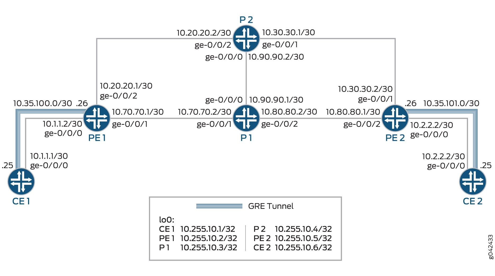
In Figure 5, GMPLS RSVP-TE VLAN LSP signaling is used to establish the Layer 2 services between the client routers, Router CE1 and Router CE2. The server routers, Router PE1 and Router PE2, have a GRE tunnel established with each of the directly connected client routers. Routers P1 and P2 are also server routers in the server-layer network.
Configuration
CLI Quick Configuration
To quickly configure this example, copy the following commands, paste them into a
text file, remove any line breaks, change any details necessary to match your
network configuration, copy and paste the commands into the CLI at the
[edit] hierarchy level, and then enter
commit from configuration mode.
CE1
set interfaces ge-0/0/0 vlan-tagging
set interfaces ge-0/0/0 unit 1 vlan-id 1
set interfaces ge-0/0/0 unit 1 family inet address 10.1.1.1/30
set interfaces ge-0/0/0 unit 1 family mpls
set interfaces ge-0/0/0 unit 10 vlan-id 10
set interfaces ge-0/0/0 unit 10 family inet address 10.10.10.1/24
set interfaces ge-0/0/0 unit 10 family mpls
set interfaces gre unit 0 tunnel source 10.1.1.1
set interfaces gre unit 0 tunnel destination 10.1.1.2
set interfaces gre unit 0 family inet address 10.35.100.25/30
set interfaces lo0 unit 0 family inet address 10.255.10.1/32
set routing-options router-id 10.255.10.1
set protocols rsvp interface all
set protocols rsvp interface fxp0.0 disable
set protocols rsvp peer-interface PE1
set protocols mpls no-cspf
set protocols mpls label-switched-path CE1-to-CE2 from 10.255.10.1
set protocols mpls label-switched-path CE1-to-CE2 to 10.255.10.6
set protocols mpls label-switched-path CE1-to-CE2 lsp-attributes switching-type ethernet-vlan
set protocols mpls label-switched-path CE1-to-CE2 lsp-attributes upstream-label vlan-id 10
set protocols mpls label-switched-path CE1-to-CE2 bandwidth 100m
set protocols mpls label-switched-path CE1-to-CE2 primary path1
set protocols mpls path path1 10.35.1.2 strict
set protocols mpls path path1 10.255.10.5 loose
set protocols mpls path path1 10.36.1.1 strict
set protocols mpls interface all
set protocols mpls interface fxp0.0 disable
set protocols link-management te-link link10 local-address 10.35.1.1
set protocols link-management te-link link10 remote-address 10.35.1.2
set protocols link-management te-link link10 ethernet-vlan
set protocols link-management te-link link10 interface ge-0/0/0
set protocols link-management peer PE1 address 10.255.10.2
set protocols link-management peer PE1 control-channel gre.0
set protocols link-management peer PE1 te-link link10
PE1
set interfaces ge-0/0/0 vlan-tagging
set interfaces ge-0/0/0 encapsulation flexible-ethernet-services
set interfaces ge-0/0/0 unit 1 vlan-id 1
set interfaces ge-0/0/0 unit 1 family inet address 10.1.1.2/30
set interfaces ge-0/0/0 unit 1 family mpls
set interfaces ge-0/0/0 unit 10 encapsulation vlan-ccc
set interfaces ge-0/0/0 unit 10 vlan-id 10
set interfaces ge-0/0/1 unit 0 family inet address 10.70.70.1/30
set interfaces ge-0/0/1 unit 0 family mpls
set interfaces ge-0/0/2 unit 0 family inet address 10.20.20.1/30
set interfaces ge-0/0/2 unit 0 family mpls
set interfaces gre unit 0 tunnel source 10.1.1.2
set interfaces gre unit 0 tunnel destination 10.1.1.1
set interfaces gre unit 0 family inet address 10.35.100.26/30
set interfaces lo0 unit 0 family inet address 10.255.10.2/32
set routing-options router-id 10.255.10.2
set protocols rsvp associated-bidirectional-lsp single-sided-provisioning
set protocols rsvp interface all
set protocols rsvp interface fxp0.0 disable
set protocols rsvp peer-interface CE1 dynamic-bidirectional-transport
set protocols mpls interface all
set protocols mpls interface fxp0.0 disable
set protocols ospf traffic-engineering
set protocols ospf area 0.0.0.0 interface all
set protocols ospf area 0.0.0.0 interface fxp0.0 disable
set protocols link-management te-link link1 local-address 10.35.1.2
set protocols link-management te-link link1 remote-address 10.35.1.1
set protocols link-management te-link link1 ethernet-vlan vlan-id-range 1-1000
set protocols link-management te-link link1 interface ge-0/0/0
set protocols link-management peer CE1 address 10.255.10.1
set protocols link-management peer CE1 control-channel gre.0
set protocols link-management peer CE1 te-link link1
P1
set interfaces ge-0/0/0 unit 0 family inet address 10.90.90.1/24
set interfaces ge-0/0/0 unit 0 family mpls
set interfaces ge-0/0/1 unit 0 family inet address 10.70.70.2/24
set interfaces ge-0/0/1 unit 0 family mpls
set interfaces ge-0/0/2 unit 0 family inet address 10.80.80.2/24
set interfaces ge-0/0/2 unit 0 family mpls
set interfaces lo0 unit 0 family inet address 10.255.10.3/32
set routing-options router-id 10.255.10.3
set protocols rsvp interface all
set protocols rsvp interface fxp0.0 disable
set protocols mpls interface all
set protocols mpls interface fxp0.0 disable
set protocols ospf traffic-engineering
set protocols ospf area 0.0.0.0 interface all
set protocols ospf area 0.0.0.0 interface fxp0.0 disable
P2
set interfaces ge-0/0/0 unit 0 family inet address 10.90.90.2/30
set interfaces ge-0/0/0 unit 0 family mpls
set interfaces ge-0/0/1 unit 0 family inet address 10.30.30.1/30
set interfaces ge-0/0/1 unit 0 family mpls
set interfaces ge-0/0/2 unit 0 family inet address 10.20.20.2/30
set interfaces ge-0/0/2 unit 0 family mpls
set interfaces lo0 unit 0 family inet address 10.255.10.4/32
set routing-options router-id 10.255.10.4
set protocols rsvp interface all
set protocols rsvp interface fxp0.0 disable
set protocols mpls interface all
set protocols mpls interface fxp0.0 disable
set protocols ospf traffic-engineering
set protocols ospf area 0.0.0.0 interface all
set protocols ospf area 0.0.0.0 interface fxp0.0 disable
PE2
set interfaces ge-0/0/0 vlan-tagging
set interfaces ge-0/0/0 encapsulation flexible-ethernet-services
set interfaces ge-0/0/0 unit 0 vlan-id 1
set interfaces ge-0/0/0 unit 0 family inet address 10.2.2.2/30
set interfaces ge-0/0/0 unit 0 family mpls
set interfaces ge-0/0/0 unit 10 encapsulation vlan-ccc
set interfaces ge-0/0/0 unit 10 vlan-id 10
set interfaces ge-0/0/1 unit 0 family inet address 10.30.30.2/30
set interfaces ge-0/0/1 unit 0 family mpls
set interfaces ge-0/0/2 unit 0 family inet address 10.80.80.1/30
set interfaces ge-0/0/2 unit 0 family mpls
set interfaces gre unit 0 tunnel source 10.2.2.2
set interfaces gre unit 0 tunnel destination 10.2.2.1
set interfaces gre unit 0 family inet address 10.35.101.26/30
set interfaces lo0 unit 0 family inet address 10.255.10.5/32
set routing-options router-id 10.255.10.5
set protocols rsvp associated-bidirectional-lsp single-sided-provisioning
set protocols rsvp interface all
set protocols rsvp interface fxp0.0 disable
set protocols rsvp peer-interface CE2 dynamic-bidirectional-transport
set protocols mpls interface all
set protocols mpls interface fxp0.0 disable
set protocols ospf traffic-engineering
set protocols ospf area 0.0.0.0 interface all
set protocols ospf area 0.0.0.0 interface fxp0.0 disable
set protocols link-management te-link link1 local-address 10.36.1.2
set protocols link-management te-link link1 remote-address 10.36.1.1
set protocols link-management te-link link1 ethernet-vlan vlan-id-range 1-1000
set protocols link-management te-link link1 interface ge-0/0/0
set protocols link-management peer CE2 address 10.255.10.6
set protocols link-management peer CE2 control-channel gre.0
set protocols link-management peer CE2 te-link link1
CE2
set interfaces ge-0/0/0 vlan-tagging
set interfaces ge-0/0/0 unit 1 vlan-id 1
set interfaces ge-0/0/0 unit 1 family inet address 10.2.2.1/24
set interfaces ge-0/0/0 unit 1 family mpls
set interfaces ge-0/0/0 unit 10 vlan-id 10
set interfaces ge-0/0/0 unit 10 family inet address 10.10.10.2/24
set interfaces ge-0/0/0 unit 10 family mpls
set interfaces gre unit 0 tunnel source 10.2.2.1
set interfaces gre unit 0 tunnel destination 10.2.2.2
set interfaces gre unit 0 family inet address 10.35.101.25/30
set interfaces lo0 unit 0 family inet address 10.255.10.6/32
set routing-options router-id 10.255.10.6
set protocols rsvp interface all
set protocols rsvp interface fxp0.0 disable
set protocols rsvp peer-interface PE2
set protocols mpls interface all
set protocols mpls interface fxp0.0 disable
set protocols link-management te-link link10 local-address 10.36.1.1
set protocols link-management te-link link10 remote-address 10.36.1.2
set protocols link-management te-link link10 ethernet-vlan vlan-id-range 1-1000
set protocols link-management te-link link10 interface ge-0/0/0
set protocols link-management peer PE2 address 10.255.10.5
set protocols link-management peer PE2 control-channel gre.0
set protocols link-management peer PE2 te-link link10
Configuring the Client Router
Step-by-Step Procedure
The following example requires that you navigate various levels in the configuration hierarchy. For information about navigating the CLI, see Using the CLI Editor in Configuration Mode in the CLI User Guide.
To configure Router CE1:
Repeat this procedure for Router CE2 in the server-layer network, after modifying the appropriate interface names, addresses, and any other parameters for the router.
-
Configure the interface connecting Router CE1 to Router PE1.
[edit interfaces]
user@CE1# set ge-0/0/0 vlan-tagging
-
Configure the control VLAN for the ge-0/0/0 interface.
[edit interfaces]
user@CE1# set ge-0/0/0 unit 1 vlan-id 1
user@CE1# set ge-0/0/0 unit 1 family inet address 10.1.1.1/30
user@CE1# set ge-0/0/0 unit 1 family mpls
-
Configure the LSP VLAN on the ge-0/0/0 interface.
[edit interfaces]
user@CE1# set ge-0/0/0 unit 10 vlan-id 10
user@CE1# set ge-0/0/0 unit 10 family inet address 10.10.10.1/24
user@CE1# set ge-0/0/0 unit 10 family mpls
-
Configure the GRE tunnel as the controlling interface for Router CE1.
[edit interfaces]
user@CE1# set gre unit 0 tunnel source 10.1.1.1
user@CE1# set gre unit 0 tunnel destination 10.1.1.2
user@CE1# set gre unit 0 family inet address 10.35.100.25/30
-
Configure the loopback interface of Router CE1.
[edit interfaces]
user@CE1# set lo0 unit 0 family inet address 10.255.10.1/32
-
Configure the loopback address of Router CE1 as its router ID.
[edit routing-options]
user@CE1# set router-id 10.255.10.1
-
Enable RSVP on all the interfaces of Router CE1, excluding the management interface.
[edit protocols]
user@CE1# set rsvp interface all
user@CE1# set rsvp interface fxp0.0 disable
-
Configure the RSVP peer interface for Router CE1.
[edit protocols]
user@CE1# set rsvp peer-interface PE1
-
Disable automatic path computation for label-switched paths (LSPs).
[edit protocols]
user@CE1# set mpls no-cspf
-
Configure the LSP to connect Router CE1 to Router CE2.
[edit protocols]
user@CE1# set mpls label-switched-path CE1-to-CE2 from 10.255.10.1
user@CE1# set mpls label-switched-path CE1-to-CE2 to 10.255.10.6
-
Configure the CE1-to-CE2 LSP attributes.
[edit protocols]
user@CE1# set mpls label-switched-path CE1-to-CE2 lsp-attributes switching-type ethernet-vlan
user@CE1# set mpls label-switched-path CE1-to-CE2 lsp-attributes upstream-label vlan-id 10
user@CE1# set mpls label-switched-path CE1-to-CE2 bandwidth 100m
-
Configure the CE1-to-CE2 LSP path and path parameters.
[edit protocols]
user@CE1# set mpls label-switched-path CE1-to-CE2 primary path1
user@CE1# set mpls path path1 10.35.1.2 strict
user@CE1# set mpls path path1 10.255.10.5 loose
user@CE1# set mpls path path1 10.36.1.1 strict
-
Enable MPLS on all the interfaces of Router CE1, excluding the management interface.
[edit protocols]
user@CE1# set mpls interface all
user@CE1# set mpls interface fxp0.0 disable
-
Configure a traffic engineering link, and assign addresses for the local and remote end of the link.
[edit protocols]
user@CE1# set link-management te-link link10 local-address 10.35.1.1
user@CE1# set link-management te-link link10 remote-address 10.35.1.2
-
Enable setting up of Layer 2 VLAN LSP on the link10 traffic engineering link.
[edit protocols]
user@CE1# set link-management te-link link10 ethernet-vlan
-
Configure the Router CE1 interface as the member interface of the link10 traffic engineering link.
[edit protocols]
user@CE1# set link-management te-link link10 interface ge-0/0/0
-
Configure Router PE1 as the Link Management Protocol (LMP) peer for Router CE1, and configure the peer attributes.
[edit protocols]
user@CE1# set link-management peer PE1 address 10.255.10.2
user@CE1# set link-management peer PE1 control-channel gre.0
user@CE1# set link-management peer PE1 te-link link10
Results
From configuration mode, confirm your configuration by entering the
show interfaces, show routing-options,
and show protocols commands. If the output does not display
the intended configuration, repeat the instructions in this example to
correct the configuration.
user@CE1# show interfaces
ge-0/0/0 {
    vlan-tagging;
    unit 1 {
        vlan-id 1;
        family inet {
            address 10.1.1.1/30;
        }
        family mpls;
    }
    unit 10 {
        vlan-id 10;
        family inet {
            address 10.10.10.1/24;
        }
        family mpls;
    }
}
gre {
    unit 0 {
        tunnel {
            source 10.1.1.1;
            destination 10.1.1.2;
        }
        family inet {
            address 10.35.100.25/30;
        }
    }
}
lo0 {
    unit 0 {
        family inet {
            address 10.255.10.1/32;
        }
    }
}
user@CE1# show routing-options
router-id 10.255.10.1;
user@CE1# show protocols
rsvp {
    interface all;
    interface fxp0.0 {
        disable;
    }
    peer-interface PE1;
}
mpls {
    no-cspf;
    label-switched-path CE1-to-CE2 {
        from 10.255.10.1;
        to 10.255.10.6;
        lsp-attributes {
            switching-type ethernet-vlan;
            upstream-label {
                vlan-id 10;
            }
        }
        bandwidth 100m;
        primary path1;
    }
    path path1 {
        10.35.1.2 strict;
        10.255.10.5 loose;
        10.36.1.1 strict;
    }
    interface all;
    interface fxp0.0 {
        disable;
    }
}
link-management {
    te-link link10 {
        local-address 10.35.1.1;
        remote-address 10.35.1.2;
        ethernet-vlan;
        interface ge-0/0/0;
    }
    peer PE1 {
        address 10.255.10.2;
        control-channel gre.0;
        te-link link10;
    }
}
Configuring the Server Router
Step-by-Step Procedure
The following example requires that you navigate various levels in the configuration hierarchy. For information about navigating the CLI, see Using the CLI Editor in Configuration Mode in the CLI User Guide.
To configure Router PE1:
Repeat this procedure for Router PE2 in the server-layer network, after modifying the appropriate interface names, addresses, and any other parameters for the router.
-
Configure the interface connecting Router PE1 to Router CE1.
[edit interfaces]
user@PE1# set ge-0/0/0 vlan-tagging
user@PE1# set ge-0/0/0 encapsulation flexible-ethernet-services
-
Configure the control VLAN for the ge-0/0/0 interface.
[edit interfaces]
user@PE1# set ge-0/0/0 unit 1 vlan-id 1
user@PE1# ge-0/0/0 unit 1 family inet address 10.1.1.2/30
user@PE1# set ge-0/0/0 unit 1 family mpls
-
Configure the LSP VLAN on the ge-0/0/0 interface.
[edit interfaces]
user@PE1# set ge-0/0/0 unit 10 encapsulation vlan-ccc
user@PE1# set ge-0/0/0 unit 10 vlan-id 10
-
Configure the interface connecting Router PE1 to the core routers (Router P1 and Router P2).
[edit interfaces]
user@PE1# set ge-0/0/1 unit 0 family inet address 10.70.70.1/30
user@PE1# set ge-0/0/1 unit 0 family mpls
user@PE1# set ge-0/0/2 unit 0 family inet address 10.20.20.1/30
user@PE1# set ge-0/0/2 unit 0 family mpls
-
Configure the GRE tunnel as the controlling interface for Router PE1.
[edit interfaces]
user@PE1# set gre unit 0 tunnel source 10.1.1.2
user@PE1# set gre unit 0 tunnel destination 10.1.1.1
user@PE1# set gre unit 0 family inet address 10.35.100.26/30
-
Configure the loopback interface of Router PE1.
[edit interfaces]
user@PE1# set lo0 unit 0 family inet address 10.255.10.2/32
-
Configure the loopback address of Router PE1 as its router ID.
[edit routing-options]
user@PE1# set router-id 10.255.10.2
-
Configure an associated bidirectional LSP, and enable unidirectional reverse LSP setup for single-sided provisioned forward LSP.
[edit protocols]
user@PE1# set rsvp associated-bidirectional-lsp single-sided-provisioning
-
Enable RSVP on all the interfaces of Router PE1, excluding the management interface.
[edit protocols]
user@PE1# set rsvp interface all
user@PE1# set rsvp interface fxp0.0 disable
-
Configure the RSVP peer interface for Router PE1, and enable dynamic setup of bidirectional packet LSP for transporting nonpacket GMPLS LSP.
[edit protocols]
user@PE1# set rsvp peer-interface CE1 dynamic-bidirectional-transport
-
Enable MPLS on all the interfaces of Router PE1, excluding the management interface.
[edit protocols]
user@PE1# set mpls interface all
user@PE1# set mpls interface fxp0.0 disable
-
Configure OSPF with traffic engineering capabilities.
[edit protocols]
user@PE1# set ospf traffic-engineering
-
Enable OSPF area 0 on all the interfaces of Router PE1, excluding the management interface.
[edit protocols]
user@PE1# set ospf area 0.0.0.0 interface all
user@PE1# set ospf area 0.0.0.0 interface fxp0.0 disable
-
Configure a traffic engineering link, and assign addresses for the local and remote end of the link.
[edit protocols]
user@PE1# set link-management te-link link1 local-address 10.35.1.2
user@PE1# set link-management te-link link1 remote-address 10.35.1.1
-
Enable setting up of a Layer 2 VLAN LSP for a specific range of VLANs on the link1 traffic engineering link.
[edit protocols]
user@PE1# set link-management te-link link1 ethernet-vlan vlan-id-range 1-1000
-
Configure the Router PE1 interface as the member interface of the link1 traffic engineering link.
[edit protocols]
user@CE1# set link-management te-link link1 interface ge-0/0/0
-
Configure Router CE1 as the LMP peer for Router PE1, and configure the peer attributes.
[edit protocols]
user@CE1# set link-management peer CE1 address 10.255.10.1
user@CE1# set link-management peer CE1 control-channel gre.0
user@CE1# set link-management peer CE1 te-link link1
Results
From configuration mode, confirm your configuration by entering the
show interfaces, show routing-options,
and show protocols commands. If the output does not display
the intended configuration, repeat the instructions in this example to
correct the configuration.
user@PE1# show interfaces
ge-0/0/0 {
    vlan-tagging;
    encapsulation flexible-ethernet-services;
    unit 1 {
        vlan-id 1;
        family inet {
            address 10.1.1.2/30;
        }
        family mpls;
    }
    unit 10 {
        encapsulation vlan-ccc;
        vlan-id 10;
    }
}
ge-0/0/1 {
    unit 0 {
        family inet {
            address 10.70.70.1/30;
        }
        family mpls;
    }
}
ge-0/0/2 {
    unit 0 {
        family inet {
            address 10.20.20.1/30;
        }
        family mpls;
    }
}
gre {
    unit 0 {
        tunnel {
            source 10.1.1.2;
            destination 10.1.1.1;
        }
        family inet {
            address 10.35.100.26/30;
        }
    }
}
lo0 {
    unit 0 {
        family inet {
            address 10.255.10.2/32;
        }
    }
}
user@PE1# show routing-options
router-id 10.255.10.2;
user@PE1# show protocols
rsvp {
    associated-bidirectional-lsp single-sided-provisioning;
    interface all;
    interface fxp0.0 {
        disable;
    }
    peer-interface CE1 {
        dynamic-bidirectional-transport;
    }
}
mpls {
    interface all;
    interface fxp0.0 {
        disable;
    }
}
ospf {
    traffic-engineering;
    area 0.0.0.0 {
        interface all;
        interface fxp0.0 {
            disable;
        }
    }
}
link-management {
    te-link link1 {
        local-address 10.35.1.2;
        remote-address 10.35.1.1;
        ethernet-vlan {
            vlan-id-range 1-1000;
        }
        interface ge-0/0/0;
    }
    peer CE1 {
        address 10.255.10.1;
        control-channel gre.0;
        te-link link1;
    }
}
Verification
Confirm that the configuration is working properly.
- Verifying the Traffic Engineering Link Status on the Client Routers
- Verifying the RSVP Session Status on the Client Routers
- Verifying the LSP Status on the Server Router
- Verifying the CCC Entries in the MPLS Routing Table of the Server Routers
- Verifying End-to-End Connectivity
Verifying the Traffic Engineering Link Status on the Client Routers
Purpose
Verify the status of the traffic engineering link configured between Router CE1 and Router CE2.
Action
From operational mode, run the show link-management and the show link-management te-link detail commands.
user@CE1> show link-management
Peer name: PE1, System identifier: 50740
 State: Up, Control address: 10.255.10.2
 Hello interval: 150, Hello dead interval: 500
   Control-channel                   State
   gre.0                             Active
  TE links:
   link10

 TE link name: link10, State: Up
  Local identifier: 65075, Remote identifier: 0, Local address: 10.35.1.1, Remote address: 10.35.1.2, Encoding: Ethernet, Switching: EVPL, Minimum bandwidth: 0bps,
  Maximum bandwidth: 1000Mbps, Total bandwidth: 1000Mbps, Available bandwidth: 900Mbps
    Name                             State Local ID  Remote ID      Bandwidth Used  LSP-name
ge-0/0/0 Up 54183 0 1000Mbps Yes CE1-to-CE2user@CE1> show link-management te-link detail
TE link name: link10, State: Up
Local identifier: 65075, Remote identifier: 0, Local address: 10.35.1.1, Remote address: 10.35.1.2, Encoding: Ethernet, Switching: EVPL, Minimum bandwidth: 0bps,
Maximum bandwidth: 1000Mbps, Total bandwidth: 1000Mbps, Available bandwidth: 900Mbps
Resource: ge-0/0/0, Type: IFD, System identifier: 137, State: Up, Local identifier: 54183, Remote identifier: 0
Total bandwidth: 1000Mbps, Unallocated bandwidth: 900Mbps
Traffic parameters: Encoding: Ethernet, Switching: EVPL, Granularity: Unknown
Maximum allocations: 4094, Number of allocations: 1, Unique allocations: 1, In use: Yes
LSP name: CE1-to-CE2, Local label: 10, Remote label: 10, Allocated bandwidth: 100Mbpsuser@CE2> show link-management
Peer name: PE2, System identifier: 50743
State: Up, Control address: 10.255.10.5
Hello interval: 150, Hello dead interval: 500
Control-channel State
gre.0 Active
TE links:
link10
TE link name: link10, State: Up
Local identifier: 65075, Remote identifier: 0, Local address: 10.36.1.1, Remote address: 10.36.1.2, Encoding: Ethernet, Switching: EVPL, Minimum bandwidth: 0bps,
Maximum bandwidth: 1000Mbps, Total bandwidth: 1000Mbps, Available bandwidth: 900Mbps
Name State Local ID Remote ID Bandwidth Used LSP-name
ge-0/0/0 Up 54183 0 1000Mbps Yes CE1-to-CE2Meaning
The Link Management Protocol (LMP) peering has been established between the client routers, and the traffic engineering link is up on both Routers CE1 and CE2.
Verifying the RSVP Session Status on the Client Routers
Purpose
Verify the status of the RSVP sessions between Router CE1 and Router CE2.
Action
From operational mode, run the show rsvp session command.
user@CE1> show rsvp session
Ingress RSVP: 1 sessions
To              From            State   Rt Style Labelin Labelout LSPname
10.255.10.6     10.255.10.1     Up       0  1 FF       -       10 CE1-to-CE2 Bidir
Total 1 displayed, Up 1, Down 0

Egress RSVP: 0 sessions
Total 0 displayed, Up 0, Down 0

Transit RSVP: 0 sessions
Total 0 displayed, Up 0, Down 0
user@CE2> show rsvp session
Ingress RSVP: 0 sessions
Total 0 displayed, Up 0, Down 0

Egress RSVP: 1 sessions
To              From            State   Rt Style Labelin Labelout LSPname
10.255.10.6     10.255.10.1     Up       0  1 FF      10        - CE1-to-CE2 Bidir
Total 1 displayed, Up 1, Down 0

Transit RSVP: 0 sessions
Total 0 displayed, Up 0, Down 0
Meaning
The RSVP sessions are established between the ingress router, Router CE1, and the egress router, Router CE2.
Verifying the LSP Status on the Server Router
Purpose
Verify the status of the MPLS LSP on Router PE1.
Action
From operational mode, run the show mpls lsp command.
user@PE1> show mpls lsp
Ingress LSP: 1 sessions
To              From            State Rt P     ActivePath       LSPname
10.255.10.5     10.255.10.2     Up     0 *                      vlan:0:10:8176:10.255.10.2->10.255.10.5 Assoc-Bidir
Total 1 displayed, Up 1, Down 0

Egress LSP: 1 sessions
To              From            State   Rt Style Labelin Labelout LSPname
10.255.10.2     10.255.10.5     Up       0  1 FF       3        - vlan:0:10:8176:10.255.10.2->10.255.10.5:rev
Total 1 displayed, Up 1, Down 0

Transit LSP: 1 sessions
To              From            State   Rt Style Labelin Labelout LSPname
10.255.10.6     10.255.10.1     Up       0  1 FF      10   299808 CE1-to-CE2 Bidir
Total 1 displayed, Up 1, Down 0
Meaning
The CE1-to-CE2 LSP is established, and the output displays the LSP attributes.
Verifying the CCC Entries in the MPLS Routing Table of the Server Routers
Purpose
Verify the circuit cross-connect (CCC) interface entries in the MPLS routing table.
Action
From operational mode, run the show route table mpls.0 and the show route forwarding-table ccc ccc-interface commands.
user@PE1> show route table mpls.0
mpls.0: 6 destinations, 6 routes (6 active, 0 holddown, 0 hidden)
+ = Active Route, - = Last Active, * = Both

0                  *[MPLS/0] 1d 22:14:51, metric 1
                      Receive
1                  *[MPLS/0] 1d 22:14:51, metric 1
                      Receive
2                  *[MPLS/0] 1d 22:14:51, metric 1
                      Receive
13                 *[MPLS/0] 1d 22:14:51, metric 1
                      Receive
299824             *[RSVP/7/1] 17:32:07, metric 1
                    > via ge-0/0/0.10, Pop
ge-0/0/0.10        *[RSVP/7/1] 17:32:07, metric 1
> to 10.20.20.2 via ge-0/0/2.0, label-switched-path CE1-to-CE2user@PE1> show route forwarding-table ccc ge-0/0/0.10 Routing table: default.mpls MPLS: Destination Type RtRef Next hop Type Index NhRef Netif ge-0/0/0.10 (CCC) user 0 10.20.20.2 Push 299808, Push 299872(top) 581 2 ge-0/0/2.0 Routing table: __mpls-oam__.mpls MPLS: Destination Type RtRef Next hop Type Index NhRef Netif default perm 0 dscd 534 1
Meaning
The output displays the CCC interface that is the client-router-facing interface and the next-hop details for that interface.
Verifying End-to-End Connectivity
Purpose
Verify the connectivity between Router CE1 and the remote client router, Router CE2.
Action
From operational mode, run the ping command.
user@CE1> ping 10.10.10.2
PING 10.10.10.2 (10.10.10.2): 56 data bytes
64 bytes from 10.10.10.2: icmp_seq=0 ttl=64 time=15.113 ms
64 bytes from 10.10.10.2: icmp_seq=1 ttl=64 time=13.353 ms
64 bytes from 10.10.10.2: icmp_seq=2 ttl=64 time=13.769 ms
64 bytes from 10.10.10.2: icmp_seq=3 ttl=64 time=10.341 ms
64 bytes from 10.10.10.2: icmp_seq=4 ttl=64 time=12.597 ms
^C
--- 10.10.10.2 ping statistics ---
5 packets transmitted, 5 packets received, 0% packet loss
round-trip min/avg/max/stddev = 10.341/13.035/15.113/1.575 ms
Meaning
The ping from Router CE1 to Router CE2 is successful.