ON THIS PAGE
Example: Tunneling LDP over SR-TE in OSPF Network
Overview
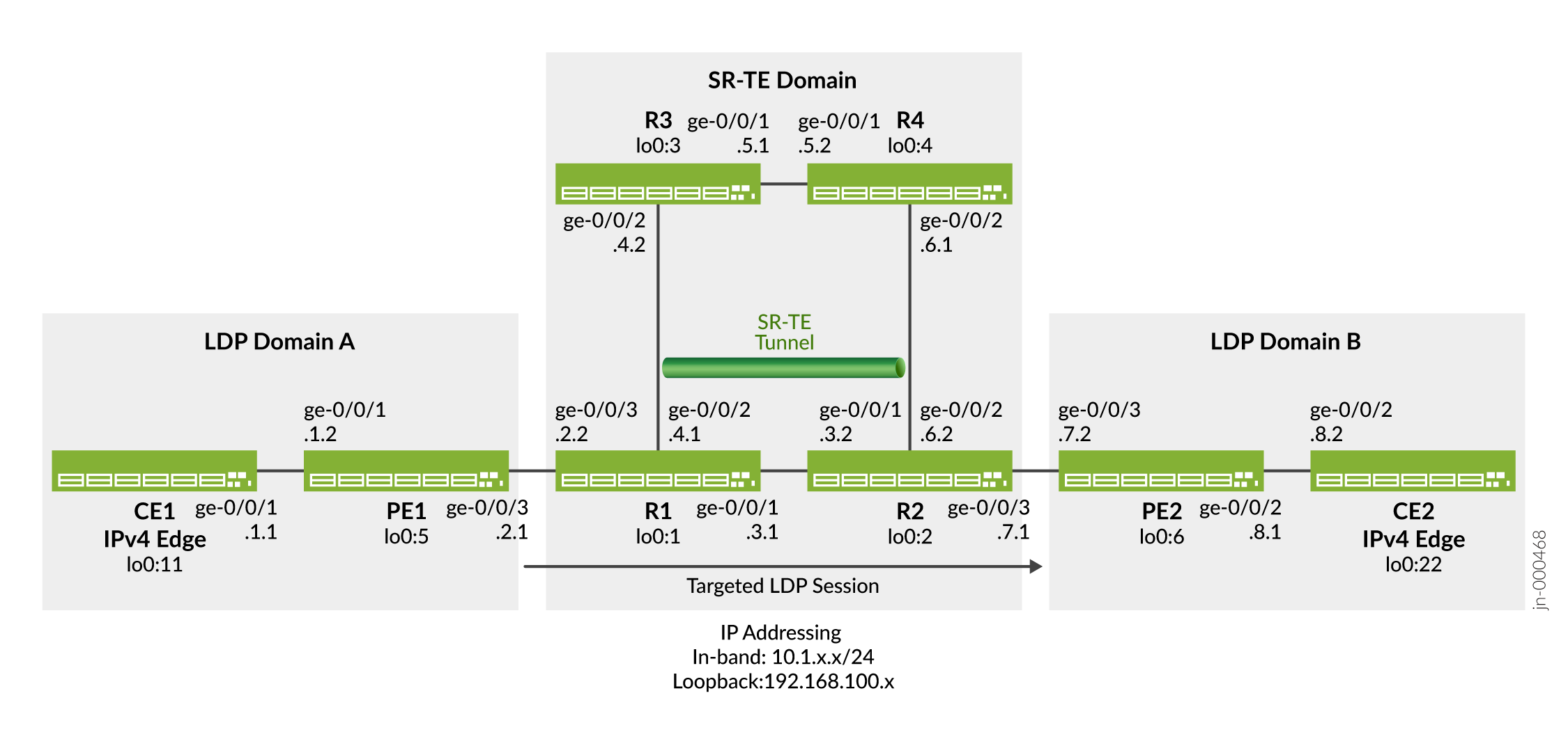
This example shows how to configure LDP tunneling over SR-TE in an OSPF network. This is illustrated by verifying that the LDP over SR-TE tunnel is enabled and the LDP tunnel to the remote edge device takes the right path. It also shows that the route to the remote edge device uses LDP forwarding and is tunneled over SR-TE. In the following topology (Figure 1), PE1 and PE2 are ingress and egress devices that support IPv4 only devices CE1 and CE2. The devices R1, R2, R3, and R4 comprise an IPv4 only SR-TE core network. The topology shows two LDP domains: LDP domain consists of devices CE1 and PE1; LDP domain B consists of devices PE2 and CE2. The LDP domains are connected to the SR-TE core network, which extends the LSP session over the core by tunneling them over SR-TE.
Topology
Requirements
This example uses the following hardware and software components:
-
MX Series routers as CE, PE, and core routers.
-
Junos OS Release 22.4R1 or later running on all devices.
Configuration
To tunnel LDP LSP over SR-TE in your core network, perform these tasks:
CLI Quick Configuration
To quickly configure this example, copy the following commands, paste them into a
text file, remove any line breaks, change any details necessary to match your
network configuration, copy and paste the commands into the CLI at the
[edit] hierarchy level, and then enter
commit from configuration mode.
enhanced-ip statement and commit the
configuration, the following warning message appears prompting you to reboot the
router:'chassis' WARNING: Chassis configuration for network services has been changed. A system reboot is mandatory. Please reboot the system NOW. Continuing without a reboot might result in unexpected system behavior. commit complete
Device CE1
set chassis network-services enhanced-ip
set interfaces ge-0/0/1 description CE1-to-PE1
set interfaces ge-0/0/1 unit 0 family inet address 10.1.1.1/24
set interfaces lo0 unit 0 family inet address 192.168.100.11/32
set protocols ospf area 0.0.0.0 interface ge-0/0/1.0
set protocols ospf area 0.0.0.0 interface lo0.0 passive
set routing-options router-id 192.168.100.11
Device PE1
set chassis network-services enhanced-ip
set interfaces ge-0/0/1 description PE1-to-CE1
set interfaces ge-0/0/1 unit 0 family inet address 10.1.1.2/24
set interfaces ge-0/0/1 unit 0 family mpls maximum-labels 8
set interfaces ge-0/0/3 description PE1-to-R1
set interfaces ge-0/0/3 unit 0 family inet address 10.1.2.1/24
set interfaces ge-0/0/3 unit 0 family mpls maximum-labels 8
set interfaces lo0 unit 0 family inet address 192.168.100.5/32
set interfaces lo0 unit 0 family mpls
set policy-options policy-statement export_bgp term a from protocol bgp
set policy-options policy-statement export_bgp term a from protocol direct
set policy-options policy-statement export_bgp term a then accept
set routing-instances CE1_vpn1 instance-type vrf
set routing-instances CE1_vpn1 protocols ospf area 0.0.0.0 interface ge-0/0/1.0
set routing-instances CE1_vpn1 protocols ospf export export_bgp
set routing-instances CE1_vpn1 interface ge-0/0/1.0
set routing-instances CE1_vpn1 route-distinguisher 192.168.100.5:1
set routing-instances CE1_vpn1 vrf-target target:100:4
set routing-instances CE1_vpn1 vrf-table-label
set routing-options router-id 192.168.100.5
set routing-options autonomous-system 65410
set protocols bgp group ibgp1 type internal
set protocols bgp group ibgp1 local-address 192.168.100.5
set protocols bgp group ibgp1 family inet unicast
set protocols bgp group ibgp1 family inet-vpn unicast
set protocols bgp group ibgp1 neighbor 192.168.100.6
set protocols ldp interface ge-0/0/3.0
set protocols ldp interface lo0.0
set protocols mpls interface ge-0/0/3.0
set protocols ospf area 0.0.0.0 interface ge-0/0/3.0 point-to-point
set protocols ospf area 0.0.0.0 interface lo0.0 passive
Device R1
set chassis network-services enhanced-ip
set interfaces ge-0/0/1 description R1-to-R2
set interfaces ge-0/0/1 unit 0 family inet address 10.1.3.1/24
set interfaces ge-0/0/1 unit 0 family mpls maximum-labels 8
set interfaces ge-0/0/2 description R1-to-R3
set interfaces ge-0/0/2 unit 0 family inet address 10.1.4.1/24
set interfaces ge-0/0/2 unit 0 family mpls maximum-labels 8
set interfaces ge-0/0/3 description R1-to-PE1
set interfaces ge-0/0/3 unit 0 family inet address 10.1.2.2/24
set interfaces ge-0/0/3 unit 0 family mpls maximum-labels 8
set interfaces lo0 unit 0 family inet address 192.168.100.1/32
set interfaces lo0 unit 0 family mpls
set routing-options router-id 192.168.100.1
set protocols ldp auto-targeted-session
set protocols ldp preference 1
set protocols ldp interface ge-0/0/1.0
set protocols ldp interface ge-0/0/3.0
set protocols ldp interface lo0.0
set protocols mpls interface ge-0/0/1.0
set protocols mpls interface ge-0/0/2.0
set protocols mpls interface ge-0/0/3.0
set protocols ospf backup-spf-options use-post-convergence-lfa
set protocols ospf backup-spf-options use-source-packet-routing
set protocols ospf traffic-engineering l3-unicast-topology
set protocols ospf traffic-engineering credibility-protocol-preference
set protocols ospf traffic-engineering advertisement always
set protocols ospf traffic-engineering tunnel-source-protocol spring-te
set protocols ospf source-packet-routing node-segment ipv4-index 5001
set protocols ospf source-packet-routing srgb start-label 80000
set protocols ospf source-packet-routing srgb index-range 50000
set protocols ospf area 0.0.0.0 interface ge-0/0/1.0 point-to-point
set protocols ospf area 0.0.0.0 interface ge-0/0/1.0 post-convergence-lfa
set protocols ospf area 0.0.0.0 interface ge-0/0/1.0 ipv4-adjacency-segment protected index 108
set protocols ospf area 0.0.0.0 interface ge-0/0/1.0 ipv4-adjacency-segment unprotected index 110
set protocols ospf area 0.0.0.0 interface ge-0/0/2.0 point-to-point
set protocols ospf area 0.0.0.0 interface ge-0/0/2.0 post-convergence-lfa
set protocols ospf area 0.0.0.0 interface ge-0/0/2.0 ipv4-adjacency-segment protected index 104
set protocols ospf area 0.0.0.0 interface ge-0/0/2.0 ipv4-adjacency-segment unprotected index 106
set protocols ospf area 0.0.0.0 interface ge-0/0/3.0 point-to-point
set protocols ospf area 0.0.0.0 interface ge-0/0/3.0 post-convergence-lfa
set protocols ospf area 0.0.0.0 interface ge-0/0/3.0 ipv4-adjacency-segment protected index 100
set protocols ospf area 0.0.0.0 interface ge-0/0/3.0 ipv4-adjacency-segment unprotected index 102
set protocols ospf area 0.0.0.0 interface lo0.0 passive
set protocols source-packet-routing segment-list seg1 inherit-label-nexthops
set protocols source-packet-routing segment-list seg1 auto-translate
set protocols source-packet-routing segment-list seg1 hop1 ip-address 10.1.4.2
set protocols source-packet-routing segment-list seg1 hop2 ip-address 10.1.5.2
set protocols source-packet-routing segment-list seg1 hop3 ip-address 10.1.6.2
set protocols source-packet-routing source-routing-path sr_static_r5 ldp-tunneling
set protocols source-packet-routing source-routing-path sr_static_r5 to 192.168.100.2
set protocols source-packet-routing source-routing-path sr_static_r5 binding-sid 1003001
set protocols source-packet-routing source-routing-path sr_static_r5 primary seg1
Device R2
set chassis network-services enhanced-ip
set interfaces ge-0/0/1 description R2-to-R1
set interfaces ge-0/0/1 unit 0 family inet address 10.1.3.2/24
set interfaces ge-0/0/1 unit 0 family mpls maximum-labels 8
set interfaces ge-0/0/2 description R2-to-R4
set interfaces ge-0/0/2 unit 0 family inet address 10.1.6.2/24
set interfaces ge-0/0/2 unit 0 family mpls maximum-labels 8
set interfaces ge-0/0/3 description R2-to-PE2
set interfaces ge-0/0/3 unit 0 family inet address 10.1.7.1/24
set interfaces ge-0/0/3 unit 0 family mpls maximum-labels 8
set interfaces lo0 unit 0 family inet address 192.168.100.2/32
set interfaces lo0 unit 0 family mpls
set routing-options router-id 192.168.100.2
set protocols ldp auto-targeted-session
set protocols ldp preference 1
set protocols ldp interface ge-0/0/1.0
set protocols ldp interface ge-0/0/3.0
set protocols ldp interface lo0.0
set protocols mpls interface ge-0/0/1.0
set protocols mpls interface ge-0/0/2.0
set protocols mpls interface ge-0/0/3.0
set protocols ospf backup-spf-options use-post-convergence-lfa
set protocols ospf backup-spf-options use-source-packet-routing
set protocols ospf traffic-engineering l3-unicast-topology
set protocols ospf traffic-engineering credibility-protocol-preference
set protocols ospf traffic-engineering advertisement always
set protocols ospf traffic-engineering tunnel-source-protocol spring-te
set protocols ospf source-packet-routing node-segment ipv4-index 5002
set protocols ospf source-packet-routing srgb start-label 80000
set protocols ospf source-packet-routing srgb index-range 50000
set protocols ospf area 0.0.0.0 interface ge-0/0/1.0 point-to-point
set protocols ospf area 0.0.0.0 interface ge-0/0/1.0 post-convergence-lfa
set protocols ospf area 0.0.0.0 interface ge-0/0/1.0 ipv4-adjacency-segment protected index 500
set protocols ospf area 0.0.0.0 interface ge-0/0/1.0 ipv4-adjacency-segment unprotected index 502
set protocols ospf area 0.0.0.0 interface ge-0/0/2.0 point-to-point
set protocols ospf area 0.0.0.0 interface ge-0/0/2.0 post-convergence-lfa
set protocols ospf area 0.0.0.0 interface ge-0/0/2.0 ipv4-adjacency-segment protected index 504
set protocols ospf area 0.0.0.0 interface ge-0/0/2.0 ipv4-adjacency-segment unprotected index 506
set protocols ospf area 0.0.0.0 interface ge-0/0/3.0 point-to-point
set protocols ospf area 0.0.0.0 interface ge-0/0/3.0 post-convergence-lfa
set protocols ospf area 0.0.0.0 interface ge-0/0/3.0 ipv4-adjacency-segment protected index 508
set protocols ospf area 0.0.0.0 interface ge-0/0/3.0 ipv4-adjacency-segment unprotected index 510
set protocols ospf area 0.0.0.0 interface lo0.0 passive
set protocols source-packet-routing segment-list seg1 inherit-label-nexthops
set protocols source-packet-routing segment-list seg1 auto-translate
set protocols source-packet-routing segment-list seg1 hop1 ip-address 10.1.6.1
set protocols source-packet-routing segment-list seg1 hop2 ip-address 10.1.5.1
set protocols source-packet-routing segment-list seg1 hop3 ip-address 10.1.4.1
set protocols source-packet-routing source-routing-path sr_static_r1 ldp-tunneling
set protocols source-packet-routing source-routing-path sr_static_r1 to 192.168.100.1
set protocols source-packet-routing source-routing-path sr_static_r1 binding-sid 1003001
set protocols source-packet-routing source-routing-path sr_static_r1 primary seg1
Device R3
set chassis network-services enhanced-ip
set interfaces ge-0/0/1 description R3-to-R4
set interfaces ge-0/0/1 unit 0 family inet address 10.1.5.1/24
set interfaces ge-0/0/1 unit 0 family mpls
set interfaces ge-0/0/2 description R3-to-R1
set interfaces ge-0/0/2 unit 0 family inet address 10.1.4.2/24
set interfaces ge-0/0/2 unit 0 family mpls
set interfaces lo0 unit 0 family inet address 192.168.100.3/32
set interfaces lo0 unit 0 family mpls
set routing-options router-id 192.168.100.3
set protocols mpls interface ge-0/0/1.0
set protocols mpls interface ge-0/0/2.0
set protocols ospf backup-spf-options use-post-convergence-lfa
set protocols ospf backup-spf-options use-source-packet-routing
set protocols ospf traffic-engineering l3-unicast-topology
set protocols ospf traffic-engineering credibility-protocol-preference
set protocols ospf traffic-engineering advertisement always
set protocols ospf source-packet-routing node-segment ipv4-index 5003
set protocols ospf source-packet-routing srgb start-label 80000
set protocols ospf source-packet-routing srgb index-range 50000
set protocols ospf area 0.0.0.0 interface ge-0/0/1.0 point-to-point
set protocols ospf area 0.0.0.0 interface ge-0/0/1.0 post-convergence-lfa
set protocols ospf area 0.0.0.0 interface ge-0/0/1.0 ipv4-adjacency-segment protected index 204
set protocols ospf area 0.0.0.0 interface ge-0/0/1.0 ipv4-adjacency-segment unprotected index 206
set protocols ospf area 0.0.0.0 interface ge-0/0/2.0 point-to-point
set protocols ospf area 0.0.0.0 interface ge-0/0/2.0 post-convergence-lfa
set protocols ospf area 0.0.0.0 interface ge-0/0/2.0 ipv4-adjacency-segment protected index 200
set protocols ospf area 0.0.0.0 interface ge-0/0/2.0 ipv4-adjacency-segment unprotected index 202
set protocols ospf area 0.0.0.0 interface lo0.0 passive
Device R4
set chassis network-services enhanced-ip
set interfaces ge-0/0/1 description R4-to-R3
set interfaces ge-0/0/1 unit 0 family inet address 10.1.5.2/24
set interfaces ge-0/0/1 unit 0 family mpls
set interfaces ge-0/0/2 description R4-to-R2
set interfaces ge-0/0/2 unit 0 family inet address 10.1.6.1/24
set interfaces ge-0/0/2 unit 0 family mpls
set interfaces lo0 unit 0 family inet address 192.168.100.4/32
set interfaces lo0 unit 0 family mpls
set routing-options router-id 192.168.100.4
set protocols mpls interface ge-0/0/1.0
set protocols mpls interface ge-0/0/2.0
set protocols ospf backup-spf-options use-post-convergence-lfa
set protocols ospf backup-spf-options use-source-packet-routing
set protocols ospf traffic-engineering l3-unicast-topology
set protocols ospf traffic-engineering credibility-protocol-preference
set protocols ospf traffic-engineering advertisement always
set protocols ospf source-packet-routing node-segment ipv4-index 5004
set protocols ospf source-packet-routing srgb start-label 80000
set protocols ospf source-packet-routing srgb index-range 50000
set protocols ospf area 0.0.0.0 interface ge-0/0/1.0 point-to-point
set protocols ospf area 0.0.0.0 interface ge-0/0/1.0 post-convergence-lfa
set protocols ospf area 0.0.0.0 interface ge-0/0/1.0 ipv4-adjacency-segment protected index 300
set protocols ospf area 0.0.0.0 interface ge-0/0/1.0 ipv4-adjacency-segment unprotected index 302
set protocols ospf area 0.0.0.0 interface ge-0/0/2.0 point-to-point
set protocols ospf area 0.0.0.0 interface ge-0/0/2.0 post-convergence-lfa
set protocols ospf area 0.0.0.0 interface ge-0/0/2.0 ipv4-adjacency-segment protected index 304
set protocols ospf area 0.0.0.0 interface ge-0/0/2.0 ipv4-adjacency-segment unprotected index 306
set protocols ospf area 0.0.0.0 interface lo0.0 passive
Device PE2
set chassis network-services enhanced-ip
set interfaces ge-0/0/2 description PE2-to-CE2
set interfaces ge-0/0/2 unit 0 family inet address 10.1.8.1/24
set interfaces ge-0/0/2 unit 0 family mpls maximum-labels 8
set interfaces ge-0/0/3 description PE2-to-R2
set interfaces ge-0/0/3 unit 0 family inet address 10.1.7.2/24
set interfaces ge-0/0/3 unit 0 family mpls maximum-labels 8
set interfaces lo0 unit 0 family inet address 192.168.100.6/32
set interfaces lo0 unit 0 family mpls
set policy-options policy-statement export_bgp term a from protocol bgp
set policy-options policy-statement export_bgp term a from protocol direct
set policy-options policy-statement export_bgp term a then accept
set routing-instances CE2_vpn1 instance-type vrf
set routing-instances CE2_vpn1 protocols ospf area 0.0.0.0 interface ge-0/0/2.0
set routing-instances CE2_vpn1 protocols ospf export export_bgp
set routing-instances CE2_vpn1 interface ge-0/0/2.0
set routing-instances CE2_vpn1 route-distinguisher 192.168.100.6:1
set routing-instances CE2_vpn1 vrf-target target:100:4
set routing-instances CE2_vpn1 vrf-table-label
set routing-options router-id 192.168.100.6
set routing-options autonomous-system 65410
set protocols bgp group ibgp1 type internal
set protocols bgp group ibgp1 local-address 192.168.100.6
set protocols bgp group ibgp1 family inet unicast
set protocols bgp group ibgp1 family inet-vpn unicast
set protocols bgp group ibgp1 neighbor 192.168.100.5
set protocols ldp interface ge-0/0/3.0
set protocols ldp interface lo0.0
set protocols mpls interface ge-0/0/3.0
set protocols ospf area 0.0.0.0 interface ge-0/0/3.0 point-to-point
set protocols ospf area 0.0.0.0 interface lo0.0 passive
Device CE2
set chassis network-services enhanced-ip
set interfaces ge-0/0/1 description CE2-to-PE2
set interfaces ge-0/0/2 unit 0 family inet address 10.1.8.2/24
set interfaces lo0 unit 0 family inet address 192.168.100.22/32
set protocols ospf area 0.0.0.0 interface ge-0/0/2.0
set protocols ospf area 0.0.0.0 interface lo0.0 passive
set routing-options router-id 192.168.100.22
Configuring PE1
Step-by-Step Procedure
The following example requires you to navigate various levels in the configuration hierarchy. For information about navigating the CLI, see Using the CLI Editor in Configuration Mode in the CLI User Guide.
To configure device PE1:
-
Configure the network services mode as Enhanced IP. Enhanced IP sets the router's network services to enhanced Internet Protocol and uses enhanced mode capabilities.
[edit chassis]
user@PE1#set network-services enhanced-ip
-
Configure the device's interfaces.
[edit interfaces]
user@PE1#set ge-0/0/1 description PE1-to-CE1
user@PE1#set ge-0/0/1 unit 0 family inet address 10.1.1.2/24
user@PE1#set ge-0/0/3 description PE1-to-R1
user@PE1#set ge-0/0/3 unit 0 family inet address 10.1.2.1/24
user@PE1#set ge-0/0/3 unit 0 family mpls
user@PE1#set lo0 unit 0 family inet address 192.168.100.5/32
user@PE1#set lo0 unit 0 family mpls
-
Configure policy options to export BGP routes to the CE router, which runs the OSPF protocol in this example.
[edit policy-options]
user@PE1#set policy-statement export_bgp term a from protocol bgp
user@PE1#set policy-statement export_bgp term a from protocol direct
user@PE1#set policy-statement export_bgp term a then accept
-
Configure a Layer 3 VPN routing instance to support the OSPF-based CE1 device.
[edit routing-instances]
user@PE1#set CE1_vpn1 instance-type vrf
user@PE1#set CE1_vpn1 protocols ospf area 0.0.0.0 interface ge-0/0/1.0
user@PE1#set CE1_vpn1 protocols ospf export export_bgp
user@PE1#set CE1_vpn1 interface ge-0/0/1.0
user@PE1#set CE1_vpn1 route-distinguisher 192.168.100.5:1
user@PE1#set CE1_vpn1 vrf-target target:100:4
user@PE1#set CE1_vpn1 vrf-table-label
-
Configure the router ID and autonomous system number for Device PE1.
[edit routing-options]
user@PE1#set router-id 192.168.100.5
userPE1# set autonomous-system 65410
-
Configure OSPF, LDP, and MPLS on the interfaces connected to the core network.
[edit protocols]
user@PE1#set ospf area 0.0.0.0 interface ge-0/0/3.0 point-to-point
user@PE1#set ospf area 0.0.0.0 lo0.0 passive
user@PE1#set ldp interface ge-0/0/3.0
user@PE1#set ldp interface lo0.0
user@PE1#set mpls interface ge-0/0/3.0
user@PE1#set mpls interface lo0.0
-
Configure BGP between the PE devices.
[edit protocols]
user@PE1#set bgp group ibgp1 type internal
user@PE1#set bgp group ibgp1 local-address 192.168.100.5
user@PE1#set bgp group ibgp1 family inet unicast
user@PE1#set bgp group ibgp1 family inet-vpn unicast
user@PE1#set bgp group ibgp1 neighbor 192.168.100.6
Results
From configuration mode, confirm your configuration by entering the
show chassis, show interfaces,
show policy-options, show
routing-instances,show routing-options, and
show protocols commands. If the output does not display
the intended configuration, repeat the instructions in this example to
correct the configuration.
user@PE1#show chassis
network-services enhanced-ip;
user@PE1#show interfaces
ge-0/0/1 {
    description PE1-to-CE1;
    unit 0 {
        family inet {
            address 10.1.1.2/24;
        }
        family mpls {
            maximum-labels 8;
        }
    }
}
ge-0/0/3 {
    description PE1-to-R1;
    unit 0 {
        family inet {
            address 10.1.2.1/24;
        }
        family mpls {
            maximum-labels 8;
        }
    }
}
lo0 {
    unit 0 {
        family inet {
            address 192.168.100.5/32;
        }
        family mpls;
    }
}
user@PE1#show policy-options
policy-statement export_bgp {
    term a {
        from protocol [ bgp direct ];
        then accept;
    }
}
user@PE1#show routing-instances
CE1_vpn1 {
    instance-type vrf;
    protocols {
        ospf {
            area 0.0.0.0 {
                interface ge-0/0/1.0;
            }
            export export_bgp;
        }
    }
    interface ge-0/0/1.0;
    route-distinguisher 192.168.100.5:1;
    vrf-target target:100:4;
    vrf-table-label;
}
user@PE1#show routing-options
router-id 192.168.100.5;
autonomous-system 65410;
user@PE1#show protocols
bgp {
    group ibgp1 {
        type internal;
        local-address 192.168.100.5;
        family inet {
            unicast;
        }
        family inet-vpn {
            unicast;
        }
        neighbor 192.168.100.6;
    }
}
ldp {
    interface ge-0/0/3.0;
    interface lo0.0;
}
mpls {
    interface ge-0/0/3.0;
    interface lo0.0;
}
ospf {
    area 0.0.0.0 {
        interface ge-0/0/3.0 {
            point-to-point;
        }
        interface lo0.0 {
            passive;
        }
    }
}
Configuring R1 Device
Step-by-Step Procedure
The following example requires you to navigate various levels in the configuration hierarchy. For information about navigating the CLI, see Using the CLI Editor in Configuration Mode in the CLI User Guide.
To configure device R1:
-
Configure the network services mode as Enhanced IP. Enhanced IP sets the router's network services to enhanced Internet Protocol and uses enhanced mode capabilities.
[edit chassis]
user@R1#set network-services enhanced-ip
After you configure the
enhanced-ipstatement and commit the configuration, the following warning message appears prompting you to reboot the router:'chassis' WARNING: Chassis configuration for network services has been changed. A system reboot is mandatory. Please reboot the system NOW. Continuing without a reboot might result in unexpected system behavior. commit complete
The reboot brings up the FPCs on the router.
-
Configure the device's interfaces.
[edit interfaces]
user@R1#set ge-0/0/1 description R1-to-R2
user@R1#set ge-0/0/1 unit 0 family inet address 10.1.3.1/24
user@R1#set ge-0/0/1 unit 0 family mpls maximum-labels 8
user@R1#set ge-0/0/2 description R1-to-R3
user@R1#set ge-0/0/2 unit 0 family inet address 10.1.4.1/24
user@R1#set ge-0/0/2 unit 0 family mpls maximum-labels 8
user@R1#set ge-0/0/3 description R1-to-PE1
user@R1#set ge-0/0/3 unit 0 family inet address 10.1.2.2/24
user@R1#set ge-0/0/3 unit 0 family mpls maximum-labels 8
user@R1#set lo0 unit 0 family inet address 192.168.100.1/32
user@R1#set lo0 unit 0 family mpls
-
Configure routing options to identify the router in the domain.
[edit routing-options]
user@R1#set router-id 192.168.100.1
-
Configure OSPF adjacency SIDs on the interfaces and allocate SRGB labels to enable segment routing. The labels in the entire SRGB are available for OSPF. Prefix SIDs (and Node SIDs) are indexed from the SRGB.
[edit protocols]
user@R1#set ospf area 0.0.0.0 interface ge-0/0/1.0 ipv4-adjacency-segment protected index 108
user@R1#set ospf area 0.0.0.0 interface ge-0/0/1.0 ipv4-adjacency-segment unprotected index 110
user@R1#set ospf area 0.0.0.0 interface ge-0/0/1.0 post-convergence-lfa
user@R1#set ospf area 0.0.0.0 interface ge-0/0/1.0 point-to-point
user@R1#set ospf area 0.0.0.0 interface ge-0/0/2.0 ipv4-adjacency-segment protected index 104
user@R1#set ospf area 0.0.0.0 interface ge-0/0/2.0 ipv4-adjacency-segment unprotected index 106
user@R1#set ospf area 0.0.0.0 interface ge-0/0/2.0 post-convergence-lfa
user@R1#set ospf area 0.0.0.0 interface ge-0/0/2.0 point-to-point
user@R1#set ospf area 0.0.0.0 interface ge-0/0/3.0 ipv4-adjacency-segment protected index 100
user@R1#set ospf area 0.0.0.0 interface ge-0/0/3.0 ipv4-adjacency-segment unprotected index 102
user@R1#set ospf area 0.0.0.0 interface ge-0/0/3.0 post-convergence-lfa
user@R1#set ospf area 0.0.0.0 interface ge-0/0/3.0 point-to-point
user@R1#set ospf area 0.0.0.0 interface lo0.0 passive
user@R1#set ospf source-packet-routing srgb start-label 80000
user@R1#set ospf source-packet-routing srgb index-range 50000
user@R1#set ospf source-packet-routing node-segment ipv4-index 5001
-
Configure TI-LFA to enable protection against link and node failures. SR using TI-LFA provides faster restoration of network connectivity by routing the traffic instantly to a backup or an alternate path if the primary path fails or becomes unavailable.
[edit protocols]
user@R1#set ospf backup-spf-options use-post-convergence-lfa
user@R1#set ospf backup-spf-options use-source-packet-routing
-
Configure OSPF traffic engineering parameters.
[edit protocols]
user@R1#set ospf traffic-engineering l3-unicast-topology
user@R1#set ospf traffic-engineering credibility-protocol-preference
user@R1#set protocols ospf traffic-engineering advertisement always
-
Enable LDP tunneling over SR-TE.
[edit protocols]
user@R1#set ospf traffic-engineering tunnel-source-protocol spring-te
-
Configure MPLS and LDP protocols on the interfaces in the LDP domain to exchange labels in the LDP domain.
[edit protocols]
user@R1#set ldp preference 1
user@R1#set protocols ldp interface ge-0/0/1.0
user@R1#set ldp interface ge-0/0/3.0
user@R1#set ldp interface lo0.0
user@R1#set mpls interface ge-0/0/1.0
user@R1#set mpls interface ge-0/0/2.0
user@R1#set mpls interface ge-0/0/3.0
user@R1#set mpls interface lo0.0
-
Enable targeted LDP session between the edge routers in the LDP domain.
[edit protocols]
user@R1#set ldp auto-targeted-session
-
Configure a segment list to route the traffic to a specific path.
[edit protocols]
user@R1#set source-packet-routing segment-list seg1 inherit-label-nexthops
user@R1#set source-packet-routing segment-list seg1 auto-translate
user@R1#set source-packet-routing segment-list seg1 hop1 ip-address 192.168.4.2
user@R1#set source-packet-routing segment-list seg1 hop2 ip-address 192.168.5.2
user@R1#set source-packet-routing segment-list seg1 hop3 ip-address 192.168.6.2
-
Configure SR-TE LSP to the remote edge routers to enable LDP tunneling over SR-TE.
[edit protocols]
user@R1#set source-packet-routing source-routing-path sr_static_r5 ldp-tunneling
user@R1#set source-packet-routing source-routing-path sr_static_r5 to 192.168.66.66
user@R1#set source-packet-routing source-routing-path sr_static_r5 binding-sid 1003001
user@R1#set source-packet-routing source-routing-path sr_static_r5 primary seg1
Results
From configuration mode, confirm your configuration by entering the
show chassis, show interfaces,
show routing-options, and show
protocols commands. If the output does not display the intended
configuration, repeat the instructions in this example to correct the
configuration.
user@R1#show chassis
network-services enhanced-ip;
user@R1#show interfaces
ge-0/0/1 {
    description R1-to-R2;
    unit 0 {
        family inet {
            address 10.1.3.1/24;
        }
        family mpls {
            maximum-labels 8;
        }
    }
}
ge-0/0/2 {
    description R1-to-R3;
    unit 0 {
        family inet {
            address 10.1.4.1/24;
        }
        family mpls {
            maximum-labels 8;
        }
    }
}
ge-0/0/3 {
    description R1-to-PE1;
    unit 0 {
        family inet {
            address 10.1.2.2/24;
        }
        family mpls {
            maximum-labels 8;
        }
    }
}
lo0 {
    unit 0 {
        family inet {
            address 192.168.100.1/32;
        }
        family mpls;
    }
}
user@R1#show protocols
ldp {
    auto-targeted-session;
    preference 1;
    interface ge-0/0/1.0;
    interface ge-0/0/3.0;
    interface lo0.0;
}
mpls {
    interface ge-0/0/1.0;
    interface ge-0/0/2.0;
    interface ge-0/0/3.0;
    interface lo0.0;
}
ospf {
    backup-spf-options {
        use-post-convergence-lfa;
        use-source-packet-routing;
    }
    traffic-engineering {
        l3-unicast-topology;
        credibility-protocol-preference;
        advertisement always;
        tunnel-source-protocol {
            spring-te;
        }
    }
    source-packet-routing {
        node-segment ipv4-index 5001;
        srgb start-label 80000 index-range 50000;
    }
    area 0.0.0.0 {
        interface ge-0/0/1.0 {
            point-to-point;
            post-convergence-lfa;
            ipv4-adjacency-segment {
                protected index 108;
                unprotected index 110;
            }
        }
        interface ge-0/0/2.0 {
            point-to-point;
            post-convergence-lfa;
            ipv4-adjacency-segment {
                protected index 104;
                unprotected index 106;
            }
        }
        interface ge-0/0/3.0 {
            point-to-point;
            post-convergence-lfa;
            ipv4-adjacency-segment {
                protected index 100;
                unprotected index 102;
            }
        }
        interface lo0.0 {
            passive;
        }
    }
}
source-packet-routing {
    segment-list seg1 {
        inherit-label-nexthops;
        auto-translate;
        hop1 ip-address 10.1.4.2;
        hop2 ip-address 10.1.5.2;
        hop3 ip-address 10.1.6.2;
    }
    source-routing-path sr_static_r5 {
        ldp-tunneling;
        to 192.168.100.2;
        binding-sid 1003001;
        primary {
            seg1;
        }
    }
}
user@R1#show routing-options
router-id 192.168.100.1;
Verification
To confirm that the configuration is working properly, perform the following tasks:
- Verifying LDP Tunneling over SR-TE
- Verifying the Advertised Label
- Verify LDP Forwarding to the Remote PE Device
- Verify End-to-End Reachability
Verifying LDP Tunneling over SR-TE
Purpose
Verify that the LDP over SR-TE tunnel is enabled and the LDP tunnel to the remote edge router is taking the right path.
Action
From operational mode, run the show spring-traffic-engineering lsp
detail command.
On R1
user@R1>show spring-traffic-engineering lsp detail
Name: sr_static_r5
  Tunnel-source: Static configuration
  Tunnel Forward Type: SRMPLS
  To: 192.168.100.2
  Te-group-id: 0
  State: Up
  LDP-tunneling enabled
    Path: seg1
    Path Status: NA
    Outgoing interface: NA
    Auto-translate status: Enabled Auto-translate result: Success
    Compute Status:Disabled , Compute Result:N/A , Compute-Profile Name:N/A
    BFD status: N/A BFD name: N/A
    BFD remote-discriminator: N/A
    Segment ID : 128
    ERO Valid: true
      SR-ERO hop count: 3
        Hop 1 (Strict):
          NAI: IPv4 Adjacency ID, 0.0.0.0 -> 10.1.4.2
          SID type: 20-bit label, Value: 80104
        Hop 2 (Strict):
          NAI: IPv4 Adjacency ID, 0.0.0.0 -> 10.1.5.2
          SID type: 20-bit label, Value: 80204
        Hop 3 (Strict):
          NAI: IPv4 Adjacency ID, 0.0.0.0 -> 10.1.6.2
          SID type: 20-bit label, Value: 80304

Total displayed LSPs: 1 (Up: 1, Down: 0)
On R2
user@R2>show spring-traffic-engineering lsp detail
Name: sr_static_r1
  Tunnel-source: Static configuration
  Tunnel Forward Type: SRMPLS
  To: 192.168.100.1
  Te-group-id: 0
  State: Up
  LDP-tunneling enabled
    Path: seg1
    Path Status: NA
    Outgoing interface: NA
    Auto-translate status: Enabled Auto-translate result: Success
    Compute Status:Disabled , Compute Result:N/A , Compute-Profile Name:N/A
    BFD status: N/A BFD name: N/A
    BFD remote-discriminator: N/A
    Segment ID : 128
    ERO Valid: true
      SR-ERO hop count: 3
        Hop 1 (Strict):
          NAI: IPv4 Adjacency ID, 0.0.0.0 -> 10.1.6.1
          SID type: 20-bit label, Value: 80504
        Hop 2 (Strict):
          NAI: IPv4 Adjacency ID, 0.0.0.0 -> 10.1.5.1
          SID type: 20-bit label, Value: 80300
        Hop 3 (Strict):
          NAI: IPv4 Adjacency ID, 0.0.0.0 -> 10.1.4.1
          SID type: 20-bit label, Value: 80200


Total displayed LSPs: 1 (Up: 1, Down: 0)
Meaning
-
On R1, the LDP tunnel is established with the remote edge router 192.168.100.2 in the SR-TE core network. You can also see the SID label values 80104, 80204, 80304 in the output.
-
On R2, the LDP tunnel is established with the remote edge router 192.168.100.1 in the SR-TE core network. You can also see the SID label values 80504, 80300, 80200 in the output.
Verifying the Advertised Label
Purpose
Verify the labels advertised for the forwarding equivalence class (FEC).
Action
From operational mode, run the show ldp database command.
On R1
Verify the labels advertised towards the directly connected PE (PE1) and the labels received from remote edge router (R2).
user@R1>show ldp database

Input label database, 192.168.100.1:0--192.168.100.2:0
Labels received: 4
  Label     Prefix
     18      192.168.100.1/32
      3      192.168.100.2/32
     20      192.168.100.5/32
     16      192.168.100.6/32


Output label database, 192.168.100.1:0--192.168.100.2:0
Labels advertised: 4
  Label     Prefix
      3      192.168.100.1/32
     4115    192.168.100.2/32
     4114    192.168.100.5/32
     4117      192.168.100.6/32

Input label database, 192.168.100.1:0--192.168.100.5:0
Labels received: 4
  Label     Prefix
     17      192.168.100.1/32
     22      192.168.100.2/32
      3      192.168.100.5/32
     24      192.168.100.6/32

Output label database, 192.168.100.1:0--192.168.100.5:0
Labels advertised: 4
  Label     Prefix
      3      192.168.100.1/32
     4115    192.168.100.2/32
     4114    192.168.100.5/32
     4117      192.168.100.6/32
On R2
Verify the labels advertised towards the directly connected PE (PE2) and the labels received from remote edge router (R1).
user@R2>show ldp database

Input label database, 192.168.100.2:0--192.168.100.1:0
Labels received: 4
  Label     Prefix
      3      192.168.100.1/32
     4115    192.168.100.2/32
     4114    192.168.100.5/32
     4117    192.168.100.6/32

Output label database, 192.168.100.2:0--192.168.100.1:0
Labels advertised: 4
  Label     Prefix
     18      192.168.100.1/32
      3      192.168.100.2/32
     20      192.168.100.5/32
     16      192.168.100.6/32

Input label database, 192.168.100.2:0--192.168.100.6:0
Labels received: 4
  Label     Prefix
     24      192.168.100.1/32
     17      192.168.100.2/32
     25      192.168.100.5/32
      3      192.168.100.6/32

Output label database, 192.168.100.2:0--192.168.100.6:0
Labels advertised: 4
  Label     Prefix
     18      192.168.100.1/32
      3      192.168.100.2/32
     20      192.168.100.5/32
     16      192.168.100.6/32
On PE1
Verify the label for the remote PE (PE2) device's loopback address is advertised by edge device R1 to the local PE (PE1) device.
user@PE1>show ldp database

Input label database, 192.168.100.5:0--192.168.100.1:0
Labels received: 4
  Label     Prefix
      3      192.168.100.1/32
     4115    192.168.100.2/32
     4114    192.168.100.5/32
     4117      192.168.100.6/32

Output label database, 192.168.100.5:0--192.168.100.1:0
Labels advertised: 4
  Label     Prefix
     17      192.168.100.1/32
     22      192.168.100.2/32
      3      192.168.100.5/32
     24      192.168.100.6/32
On PE2
Verify the label for the remote PE (PE1) device's loopback address is advertised by edge device R2 to the local PE (PE2) device.
user@PE2>show ldp database

Input label database, 192.168.100.6:0--192.168.100.2:0
Labels received: 4
  Label     Prefix
     18      192.168.100.1/32
      3      192.168.100.2/32
     20      192.168.100.5/32
     16      192.168.100.6/32

Output label database, 192.168.100.6:0--192.168.100.2:0
Labels advertised: 4
  Label     Prefix
     24      192.168.100.1/32
     17      192.168.100.2/32
     25      192.168.100.5/32
      3      192.168.100.6/32
Meaning
-
On R1, you can see label 4117 is advertised towards the directly connected PE (PE1) and the label 27 is received from remote edge router (R2).
-
On R2, you can see label 18 is advertised towards the directly connected PE (PE2) and the label 25 is received from remote edge router (R1).
-
On PE1, you can see label 4117 is received from the local edge router (R1).
-
On PE2, you can see label 18 is received from the local edge router (R2).
Verify LDP Forwarding to the Remote PE Device
Purpose
Verify that the route to the remote PE router uses LDP forwarding and is tunneled over SR-TE.
Action
From operational mode, run the show route
destination-prefix command.
On R1
Verify that the route to the remote PE (PE2) router is through LDP over SR-TE tunnel.
user@R1>show route 192.168.100.6
inet.0: 29 destinations, 29 routes (29 active, 0 holddown, 0 hidden)
+ = Active Route, - = Last Active, * = Both

192.168.100.6/32   *[OSPF/10/10] 1d 03:28:10, metric 2
                    >  to 10.1.3.2 via ge-0/0/1.0

inet.3: 10 destinations, 15 routes (5 active, 0 holddown, 8 hidden)
+ = Active Route, - = Last Active, * = Both

192.168.100.6/32   *[LDP/1] 21:42:29, metric 1
                    >  to 10.1.4.2 via ge-0/0/2.0, Push 16, Push 80304, Push 80204(top)
                       to 10.1.3.2 via ge-0/0/1.0, Push 16, Push 80304, Push 80204, Push 85003, Push 85004(top)
On R2
Verify that the route to the remote PE (PE1) router is through LDP over SR-TE tunnel.
user@R2>show route 192.168.100.5
inet.0: 29 destinations, 29 routes (29 active, 0 holddown, 0 hidden)
+ = Active Route, - = Last Active, * = Both

192.168.100.5/32   *[OSPF/10/10] 22:22:45, metric 2
                    >  to 10.1.3.1 via ge-0/0/1.0

inet.3: 10 destinations, 15 routes (5 active, 0 holddown, 8 hidden)
+ = Active Route, - = Last Active, * = Both

192.168.100.5/32   *[LDP/1] 22:22:45, metric 1
                    >  to 10.1.6.1 via ge-0/0/2.0, Push 4114, Push 80200, Push 80300(top)
                       to 10.1.3.1 via ge-0/0/1.0, Push 4114, Push 80200, Push 80300, Push 85004, Push 85003(top)
On PE1
Verify that the route to the remote PE (PE2) router is through a targeted LDP session to the remote PE.
user@PE1>show route 192.168.100.6

inet.0: 27 destinations, 27 routes (27 active, 0 holddown, 0 hidden)
+ = Active Route, - = Last Active, * = Both

192.168.100.6/32   *[OSPF/10] 01:15:29, metric 3
                    >  to 10.1.2.2 via ge-0/0/3.0

inet.3: 3 destinations, 3 routes (3 active, 0 holddown, 0 hidden)
+ = Active Route, - = Last Active, * = Both

192.168.100.6/32   *[LDP/9] 01:15:29, metric 1
                    >  to 10.1.2.2 via ge-0/0/3.0, Push 4117
On PE2
Verify that the route to the remote PE (PE1) router is through a targeted LDP session to the remote PE.
user@PE2>show route 192.168.100.5

inet.0: 27 destinations, 27 routes (27 active, 0 holddown, 0 hidden)
+ = Active Route, - = Last Active, * = Both

192.168.100.5/32   *[OSPF/10] 01:27:40, metric 3
                    >  to 10.1.7.1 via ge-0/0/3.0

inet.3: 3 destinations, 3 routes (3 active, 0 holddown, 0 hidden)
+ = Active Route, - = Last Active, * = Both

192.168.100.5/32   *[LDP/9] 01:27:40, metric 1
                    >  to 10.1.7.1 via ge-0/0/3.0, Push 20
Meaning
-
On R1, you can see the LDP label as 16 and the SR-TE label stacks as 80304, 80204, 85003, 85004.
-
On R2, you can see the LDP label as 22 and the SR-TE label stacks as 80200, 80300, 85004, 85003.
-
On PE1 and PE2, you can see the LDP label as 4117 and 20, respectively.
Verify End-to-End Reachability
Purpose
Verify CE1 can ping CE2 by using the ping 192.168.100.22 source 192.168.100.11 count 2 operational mode command.
Action
user@CE1> ping 192.168.100.22 source 192.168.100.11 count 2
PING 192.168.100.22 (192.168.100.22): 56 data bytes
64 bytes from 192.168.100.22: icmp_seq=0 ttl=58 time=8.772 ms
64 bytes from 192.168.100.22: icmp_seq=1 ttl=58 time=9.189 ms

--- 192.168.100.22 ping statistics ---
2 packets transmitted, 2 packets received, 0% packet loss
round-trip min/avg/max/stddev = 8.772/8.980/9.189/0.209 ms
Meaning
The output from CE1 shows that CE1 can ping CE2.