ON THIS PAGE
Example: Tunneling LDP over SR-TE in IS-IS Network
Use this example to learn how to tunnel LDP LSPs over SR-TE in your core network.
Our content testing team has validated and updated this example.
Requirements
This example uses the following hardware and software components:
MX Series routers as CE, PE, and core routers.
-
Junos OS Release 20.3R1 or later running on all devices.
-
Updated and revalidated using vMX on Junos OS Release 21.1R1.
-
Are you interested in getting hands-on experience on this feature?
Visit Juniper vLabs to reserve your pre-configured vLab Sandbox: Segment Routing - Basic and try it out for free!
Overview
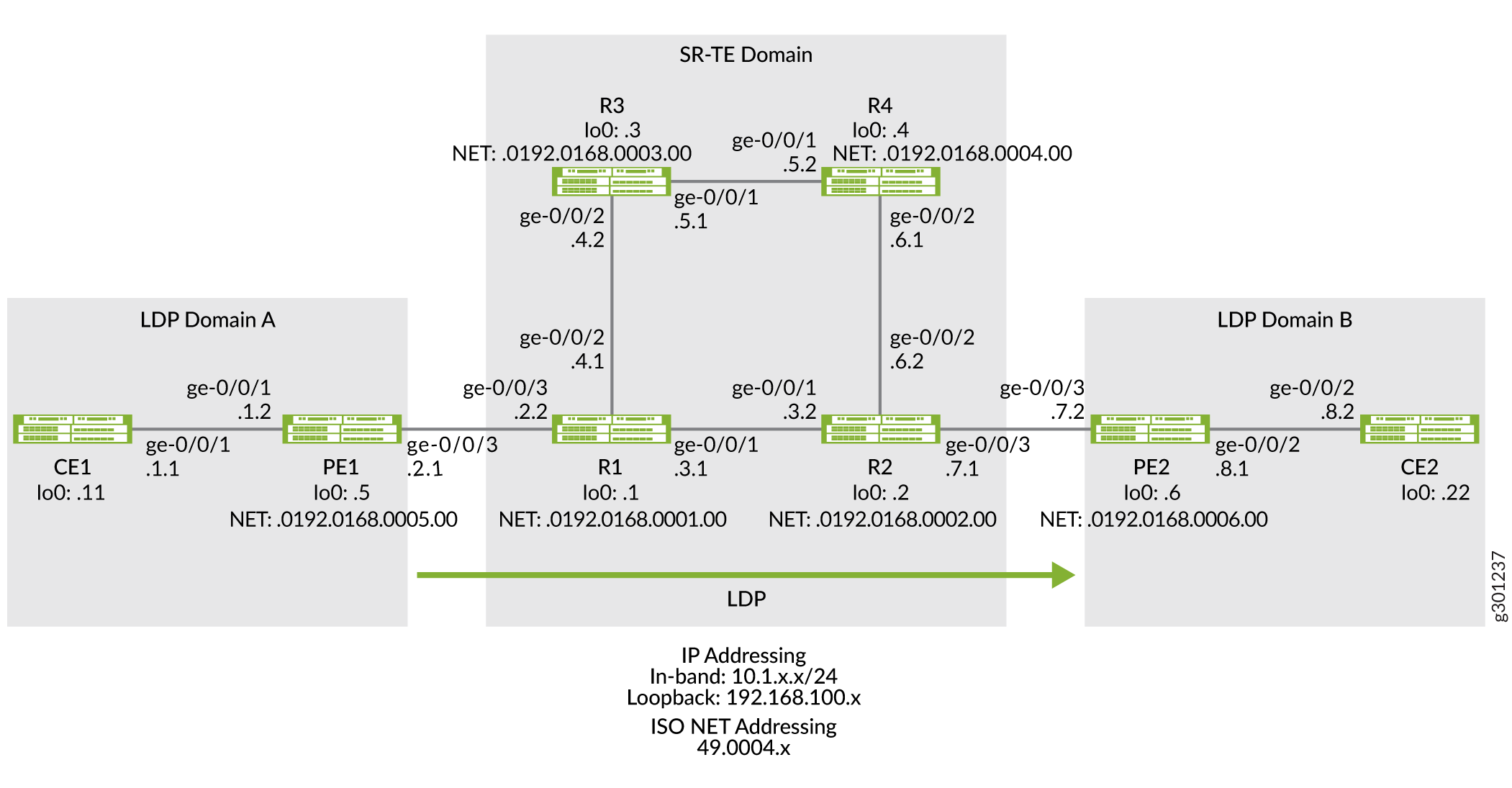
The following topology (Figure 1) shows two LDP domains (LDP Domain A and LDP Domain B) connected to the SR-TE core network, which extends the LSP session over the core by tunneling them over SR-TE.
Topology
Configuration
To tunnel LDP LSP over SR-TE in your core network, perform these tasks:
CLI Quick Configuration
To quickly configure this example, copy the
following commands, paste them into a text file, remove any line breaks,
change any details necessary to match your network configuration,
copy and paste the commands into the CLI at the [edit] hierarchy
level, and then enter commit from configuration mode.
Device CE1
set chassis network-services enhanced-ip
set interfaces ge-0/0/1 description CE1-to-PE1
set interfaces ge-0/0/1 unit 0 family inet address 10.1.1.1/24
set interfaces lo0 unit 0 family inet address 192.168.100.11/32
set protocols ospf area 0.0.0.0 interface ge-0/0/1.0
set protocols ospf area 0.0.0.0 interface lo0.0 passive
set routing-options router-id 192.168.100.11
Device PE1
set chassis network-services enhanced-ip
set interfaces ge-0/0/1 description PE1-to-CE1
set interfaces ge-0/0/1 unit 0 family inet address 10.1.1.2/24
set interfaces ge-0/0/1 unit 0 family iso
set interfaces ge-0/0/3 description PE1-to-R1
set interfaces ge-0/0/3 unit 0 family inet address 10.1.2.1/24
set interfaces ge-0/0/3 unit 0 family iso
set interfaces ge-0/0/3 unit 0 family mpls
set interfaces lo0 unit 0 family inet address 192.168.100.5/32
set interfaces lo0 unit 0 family iso address 49.0004.0192.0168.0005.00
set interfaces lo0 unit 0 family mpls
set policy-options policy-statement export_bgp term a from protocol bgp
set policy-options policy-statement export_bgp term a from protocol direct
set policy-options policy-statement export_bgp term a then accept
set routing-instances CE1_vpn1 instance-type vrf
set routing-instances CE1_vpn1 protocols ospf area 0.0.0.0 interface ge-0/0/1.0
set routing-instances CE1_vpn1 protocols ospf export export_bgp
set routing-instances CE1_vpn1 interface ge-0/0/1.0
set routing-instances CE1_vpn1 route-distinguisher 192.168.100.5:1
set routing-instances CE1_vpn1 vrf-target target:100:4
set routing-instances CE1_vpn1 vrf-table-label
set protocols bgp group ibgp1 type internal
set protocols bgp group ibgp1 local-address 192.168.100.5
set protocols bgp group ibgp1 family inet unicast
set protocols bgp group ibgp1 family inet-vpn unicast
set protocols bgp group ibgp1 neighbor 192.168.100.6
set protocols isis interface ge-0/0/3.0 point-to-point
set protocols isis interface lo0.0 passive
set protocols ldp interface ge-0/0/3.0
set protocols ldp interface lo0.0
set protocols mpls interface ge-0/0/3.0
set protocols mpls interface lo0.0
set routing-options router-id 192.168.100.5
set routing-options autonomous-system 65410
Device R1
set chassis network-services enhanced-ip
set interfaces ge-0/0/1 description R1-to-R2
set interfaces ge-0/0/1 unit 0 family inet address 10.1.3.1/24
set interfaces ge-0/0/1 unit 0 family iso
set interfaces ge-0/0/1 unit 0 family mpls maximum-labels 8
set interfaces ge-0/0/2 description R1-to-R3
set interfaces ge-0/0/2 unit 0 family inet address 10.1.4.1/24
set interfaces ge-0/0/2 unit 0 family iso
set interfaces ge-0/0/2 unit 0 family mpls maximum-labels 8
set interfaces ge-0/0/3 description R1-to-PE1
set interfaces ge-0/0/3 unit 0 family inet address 10.1.2.2/24
set interfaces ge-0/0/3 unit 0 family iso
set interfaces ge-0/0/3 unit 0 family mpls maximum-labels 8
set interfaces lo0 unit 0 family inet address 192.168.100.1/32
set interfaces lo0 unit 0 family iso address 49.0004.0192.0168.0001.00
set interfaces lo0 unit 0 family mpls
set protocols isis interface ge-0/0/1.0 level 2 ipv4-adjacency-segment protected index 108
set protocols isis interface ge-0/0/1.0 level 2 ipv4-adjacency-segment unprotected index 110
set protocols isis interface ge-0/0/1.0 level 2 ipv6-adjacency-segment protected index 109
set protocols isis interface ge-0/0/1.0 level 2 ipv6-adjacency-segment unprotected index 111
set protocols isis interface ge-0/0/1.0 level 2 post-convergence-lfa
set protocols isis interface ge-0/0/1.0 point-to-point
set protocols isis interface ge-0/0/2.0 level 2 ipv4-adjacency-segment protected index 104
set protocols isis interface ge-0/0/2.0 level 2 ipv4-adjacency-segment unprotected index 106
set protocols isis interface ge-0/0/2.0 level 2 ipv6-adjacency-segment protected index 105
set protocols isis interface ge-0/0/2.0 level 2 ipv6-adjacency-segment unprotected index 107
set protocols isis interface ge-0/0/2.0 level 2 post-convergence-lfa
set protocols isis interface ge-0/0/2.0 point-to-point
set protocols isis interface ge-0/0/3.0 level 2 ipv4-adjacency-segment protected index 100
set protocols isis interface ge-0/0/3.0 level 2 ipv4-adjacency-segment unprotected index 102
set protocols isis interface ge-0/0/3.0 level 2 ipv6-adjacency-segment protected index 101
set protocols isis interface ge-0/0/3.0 level 2 ipv6-adjacency-segment unprotected index 103
set protocols isis interface ge-0/0/3.0 level 2 post-convergence-lfa
set protocols isis interface ge-0/0/3.0 point-to-point
set protocols isis interface lo0.0 passive
set protocols isis source-packet-routing srgb start-label 80000
set protocols isis source-packet-routing srgb index-range 50000
set protocols isis source-packet-routing node-segment ipv4-index 5001
set protocols isis source-packet-routing node-segment ipv6-index 5501
set protocols isis level 1 disable
set protocols isis backup-spf-options use-post-convergence-lfa
set protocols isis backup-spf-options use-source-packet-routing
set protocols isis traffic-engineering l3-unicast-topology
set protocols isis traffic-engineering credibility-protocol-preference
set protocols isis traffic-engineering tunnel-source-protocol spring-te
set protocols ldp auto-targeted-session
set protocols ldp preference 1
set protocols ldp interface ge-0/0/1.0
set protocols ldp interface ge-0/0/3.0
set protocols ldp interface lo0.0
set protocols mpls interface ge-0/0/1.0
set protocols mpls interface ge-0/0/2.0
set protocols mpls interface ge-0/0/3.0
set protocols mpls interface lo0.0
set protocols source-packet-routing segment-list seg1 inherit-label-nexthops
set protocols source-packet-routing segment-list seg1 auto-translate
set protocols source-packet-routing segment-list seg1 hop1 ip-address 10.1.4.2
set protocols source-packet-routing segment-list seg1 hop2 ip-address 10.1.5.2
set protocols source-packet-routing segment-list seg1 hop3 ip-address 10.1.6.2
set protocols source-packet-routing source-routing-path sr_static_r5 ldp-tunneling
set protocols source-packet-routing source-routing-path sr_static_r5 to 192.168.100.2
set protocols source-packet-routing source-routing-path sr_static_r5 binding-sid 1003001
set protocols source-packet-routing source-routing-path sr_static_r5 primary seg1
set routing-options router-id 192.168.100.1
Device R2
set chassis network-services enhanced-ip
set interfaces ge-0/0/1 description R2-to-R1
set interfaces ge-0/0/1 unit 0 family inet address 10.1.3.2/24
set interfaces ge-0/0/1 unit 0 family iso
set interfaces ge-0/0/1 unit 0 family mpls maximum-labels 8
set interfaces ge-0/0/2 description R2-to-R4
set interfaces ge-0/0/2 unit 0 family inet address 10.1.6.2/24
set interfaces ge-0/0/2 unit 0 family iso
set interfaces ge-0/0/2 unit 0 family mpls maximum-labels 8
set interfaces ge-0/0/3 description R2-to-PE2
set interfaces ge-0/0/3 unit 0 family inet address 10.1.7.1/24
set interfaces ge-0/0/3 unit 0 family iso
set interfaces ge-0/0/3 unit 0 family mpls maximum-labels 8
set interfaces lo0 unit 0 family inet address 192.168.100.2/32
set interfaces lo0 unit 0 family iso address 49.0004.0192.0168.0002.00
set interfaces lo0 unit 0 family mpls
set protocols isis interface ge-0/0/1.0 level 2 ipv4-adjacency-segment protected index 500
set protocols isis interface ge-0/0/1.0 level 2 ipv4-adjacency-segment unprotected index 502
set protocols isis interface ge-0/0/1.0 level 2 ipv6-adjacency-segment protected index 501
set protocols isis interface ge-0/0/1.0 level 2 ipv6-adjacency-segment unprotected index 503
set protocols isis interface ge-0/0/1.0 level 2 post-convergence-lfa
set protocols isis interface ge-0/0/1.0 point-to-point
set protocols isis interface ge-0/0/2.0 level 2 ipv4-adjacency-segment protected index 504
set protocols isis interface ge-0/0/2.0 level 2 ipv4-adjacency-segment unprotected index 506
set protocols isis interface ge-0/0/2.0 level 2 ipv6-adjacency-segment protected index 505
set protocols isis interface ge-0/0/2.0 level 2 ipv6-adjacency-segment unprotected index 507
set protocols isis interface ge-0/0/2.0 level 2 post-convergence-lfa
set protocols isis interface ge-0/0/2.0 point-to-point
set protocols isis interface ge-0/0/3.0 level 2 ipv4-adjacency-segment protected index 508
set protocols isis interface ge-0/0/3.0 level 2 ipv4-adjacency-segment unprotected index 510
set protocols isis interface ge-0/0/3.0 level 2 ipv6-adjacency-segment protected index 509
set protocols isis interface ge-0/0/3.0 level 2 ipv6-adjacency-segment unprotected index 511
set protocols isis interface ge-0/0/3.0 level 2 post-convergence-lfa
set protocols isis interface ge-0/0/3.0 point-to-point
set protocols isis interface lo0.0 passive
set protocols isis source-packet-routing srgb start-label 80000
set protocols isis source-packet-routing srgb index-range 50000
set protocols isis source-packet-routing node-segment ipv4-index 5005
set protocols isis source-packet-routing node-segment ipv6-index 5505
set protocols isis source-packet-routing traffic-statistics statistics-granularity per-interface
set protocols isis level 1 disable
set protocols isis backup-spf-options use-post-convergence-lfa
set protocols isis backup-spf-options use-source-packet-routing
set protocols isis traffic-engineering l3-unicast-topology
set protocols isis traffic-engineering credibility-protocol-preference
set protocols isis traffic-engineering tunnel-source-protocol spring-te
set protocols ldp interface ge-0/0/1.0
set protocols ldp interface ge-0/0/3.0
set protocols ldp interface lo0.0
set protocols mpls interface ge-0/0/1.0
set protocols mpls interface ge-0/0/2.0
set protocols mpls interface ge-0/0/3.0
set protocols mpls interface lo0.0
set protocols source-packet-routing segment-list seg1 inherit-label-nexthops
set protocols source-packet-routing segment-list seg1 auto-translate
set protocols source-packet-routing segment-list seg1 hop1 ip-address 10.1.6.1
set protocols source-packet-routing segment-list seg1 hop2 ip-address 10.1.5.1
set protocols source-packet-routing segment-list seg1 hop3 ip-address 10.1.4.1
set protocols source-packet-routing source-routing-path sr_static_r1 ldp-tunneling
set protocols source-packet-routing source-routing-path sr_static_r1 to 192.168.100.1
set protocols source-packet-routing source-routing-path sr_static_r1 binding-sid 1003001
set protocols source-packet-routing source-routing-path sr_static_r1 primary seg1
set routing-options router-id 192.168.100.2
Device R3
set chassis network-services enhanced-ip
set interfaces ge-0/0/1 description R3-to-R4
set interfaces ge-0/0/1 unit 0 family inet address 10.1.5.1/24
set interfaces ge-0/0/1 unit 0 family iso
set interfaces ge-0/0/1 unit 0 family mpls
set interfaces ge-0/0/2 description R3-to-R1
set interfaces ge-0/0/2 unit 0 family inet address 10.1.4.2/24
set interfaces ge-0/0/2 unit 0 family iso
set interfaces ge-0/0/2 unit 0 family mpls
set interfaces lo0 unit 0 family inet address 192.168.100.3/32
set interfaces lo0 unit 0 family iso address 49.0004.0192.0168.0003.00
set interfaces lo0 unit 0 family mpls
set protocols isis interface ge-0/0/1.0 level 2 ipv4-adjacency-segment protected index 204
set protocols isis interface ge-0/0/1.0 level 2 ipv4-adjacency-segment unprotected index 206
set protocols isis interface ge-0/0/1.0 level 2 ipv6-adjacency-segment protected index 205
set protocols isis interface ge-0/0/1.0 level 2 ipv6-adjacency-segment unprotected index 207
set protocols isis interface ge-0/0/1.0 level 2 post-convergence-lfa
set protocols isis interface ge-0/0/1.0 point-to-point
set protocols isis interface ge-0/0/2.0 level 2 ipv4-adjacency-segment protected index 200
set protocols isis interface ge-0/0/2.0 level 2 ipv4-adjacency-segment unprotected index 202
set protocols isis interface ge-0/0/2.0 level 2 ipv6-adjacency-segment protected index 201
set protocols isis interface ge-0/0/2.0 level 2 ipv6-adjacency-segment unprotected index 203
set protocols isis interface ge-0/0/2.0 level 2 post-convergence-lfa
set protocols isis interface ge-0/0/2.0 point-to-point
set protocols isis interface lo0.0 passive
set protocols isis source-packet-routing srgb start-label 80000
set protocols isis source-packet-routing srgb index-range 50000
set protocols isis source-packet-routing node-segment ipv4-index 5003
set protocols isis source-packet-routing node-segment ipv6-index 5503
set protocols isis level 1 disable
set protocols isis backup-spf-options use-post-convergence-lfa
set protocols isis backup-spf-options use-source-packet-routing
set protocols isis traffic-engineering l3-unicast-topology
set protocols isis traffic-engineering credibility-protocol-preference
set protocols mpls interface ge-0/0/1.0
set protocols mpls interface ge-0/0/2.0
set protocols mpls interface lo0.0
set routing-options router-id 192.168.100.3
Device R4
set chassis network-services enhanced-ip
set interfaces ge-0/0/1 description R4-to-R3
set interfaces ge-0/0/1 unit 0 family inet address 10.1.5.2/24
set interfaces ge-0/0/1 unit 0 family iso
set interfaces ge-0/0/1 unit 0 family mpls
set interfaces ge-0/0/2 description R4-to-R2
set interfaces ge-0/0/2 unit 0 family inet address 10.1.6.1/24
set interfaces ge-0/0/2 unit 0 family iso
set interfaces ge-0/0/2 unit 0 family mpls
set interfaces lo0 unit 0 family inet address 192.168.100.4/32
set interfaces lo0 unit 0 family iso address 49.0004.0192.0168.0004.00
set interfaces lo0 unit 0 family mpls
set protocols isis interface ge-0/0/1.0 level 2 ipv4-adjacency-segment protected index 300
set protocols isis interface ge-0/0/1.0 level 2 ipv4-adjacency-segment unprotected index 302
set protocols isis interface ge-0/0/1.0 level 2 ipv6-adjacency-segment protected index 301
set protocols isis interface ge-0/0/1.0 level 2 ipv6-adjacency-segment unprotected index 303
set protocols isis interface ge-0/0/1.0 level 2 post-convergence-lfa
set protocols isis interface ge-0/0/1.0 point-to-point
set protocols isis interface ge-0/0/2.0 level 2 ipv4-adjacency-segment protected index 304
set protocols isis interface ge-0/0/2.0 level 2 ipv4-adjacency-segment unprotected index 306
set protocols isis interface ge-0/0/2.0 level 2 ipv6-adjacency-segment protected index 305
set protocols isis interface ge-0/0/2.0 level 2 ipv6-adjacency-segment unprotected index 307
set protocols isis interface ge-0/0/2.0 level 2 post-convergence-lfa
set protocols isis interface ge-0/0/2.0 point-to-point
set protocols isis interface lo0.0 passive
set protocols isis source-packet-routing srgb start-label 80000
set protocols isis source-packet-routing srgb index-range 50000
set protocols isis source-packet-routing node-segment ipv4-index 5004
set protocols isis source-packet-routing node-segment ipv6-index 5504
set protocols isis source-packet-routing traffic-statistics statistics-granularity per-interface
set protocols isis level 1 disable
set protocols isis backup-spf-options use-post-convergence-lfa
set protocols isis backup-spf-options use-source-packet-routing
set protocols isis traffic-engineering l3-unicast-topology
set protocols isis traffic-engineering credibility-protocol-preference
set protocols mpls interface ge-0/0/1.0
set protocols mpls interface ge-0/0/2.0
set protocols mpls interface lo0.0
set routing-options router-id 192.168.100.4
Device PE2
set chassis network-services enhanced-ip
set interfaces ge-0/0/2 description PE2-to-CE2
set interfaces ge-0/0/2 unit 0 family inet address 10.1.8.1/24
set interfaces ge-0/0/2 unit 0 family iso
set interfaces ge-0/0/2 unit 0 family mpls maximum-labels 8
set interfaces ge-0/0/3 description PE2-to-R2
set interfaces ge-0/0/3 unit 0 family inet address 10.1.7.2/24
set interfaces ge-0/0/3 unit 0 family iso
set interfaces ge-0/0/3 unit 0 family mpls maximum-labels 8
set interfaces lo0 unit 0 family inet address 192.168.100.6/32
set interfaces lo0 unit 0 family iso address 49.0004.0192.0168.0006.00
set interfaces lo0 unit 0 family mpls
set policy-options policy-statement export_bgp term a from protocol bgp
set policy-options policy-statement export_bgp term a from protocol direct
set policy-options policy-statement export_bgp term a then accept
set routing-instances CE2_vpn1 instance-type vrf
set routing-instances CE2_vpn1 protocols ospf area 0.0.0.0 interface ge-0/0/2.0
set routing-instances CE2_vpn1 protocols ospf export export_bgp
set routing-instances CE2_vpn1 interface ge-0/0/2.0
set routing-instances CE2_vpn1 route-distinguisher 192.168.100.6:1
set routing-instances CE2_vpn1 vrf-target target:100:4
set routing-instances CE2_vpn1 vrf-table-label
set protocols bgp group ibgp1 type internal
set protocols bgp group ibgp1 local-address 192.168.100.6
set protocols bgp group ibgp1 family inet unicast
set protocols bgp group ibgp1 family inet-vpn unicast
set protocols bgp group ibgp1 neighbor 192.168.100.5
set protocols isis interface ge-0/0/3.0 point-to-point
set protocols isis interface lo0.0 passive
set protocols ldp interface ge-0/0/3.0
set protocols ldp interface lo0.0
set protocols mpls interface ge-0/0/3.0
set protocols mpls interface lo0.0
set routing-options router-id 192.168.100.6
set routing-options autonomous-system 65410
Device CE2
set chassis network-services enhanced-ip
set interfaces ge-0/0/1 description CE2-to-PE2
set interfaces ge-0/0/2 unit 0 family inet address 10.1.8.2/24
set interfaces lo0 unit 0 family inet address 192.168.100.22/32
set protocols ospf area 0.0.0.0 interface ge-0/0/2.0
set protocols ospf area 0.0.0.0 interface lo0.0 passive
set routing-options router-id 192.168.100.22
Configuring PE1
Step-by-Step Procedure
The following example requires you to navigate various levels in the configuration hierarchy. For information about navigating the CLI, see Using the CLI Editor in Configuration Mode in the CLI User Guide.
To configure device PE1:
Configure the network services mode as Enhanced IP. Enhanced IP sets the router's network services to enhanced Internet Protocol and uses enhanced mode capabilities.
[edit chassis]
user@PE1#set network-services enhanced-ip
After you configure the
enhanced-ipstatement and commit the configuration, the following warning message appears prompting you to reboot the router:'chassis' WARNING: Chassis configuration for network services has been changed. A system reboot is mandatory. Please reboot the system NOW. Continuing without a reboot might result in unexpected system behavior. commit complete
The reboot brings up the FPCs on the router.
-
Configure the device's interfaces.
[edit interfaces]
user@PE1#set ge-0/0/1 description PE1-to-CE1
user@PE1#set ge-0/0/1 unit 0 family inet address 10.1.1.2/24
user@PE1#set ge-0/0/1 unit 0 family iso

user@PE1#set ge-0/0/3 description PE1-to-R1
user@PE1#set ge-0/0/3 unit 0 family inet address 10.1.2.1/24
user@PE1#set ge-0/0/3 unit 0 family iso
user@PE1#set ge-0/0/3 unit 0 family mpls

user@PE1#set lo0 unit 0 family inet address 192.168.100.5/32
user@PE1#set lo0 unit 0 family iso address 49.0004.0192.0168.0005.00
user@PE1#set lo0 unit 0 family mpls
-
Configure policy options to export BGP routes to the CE router, which runs the OSPF protocol in this example.
[edit policy-options]
user@PE1#set policy-statement export_bgp term a from protocol bgp
user@PE1#set policy-statement export_bgp term a from protocol direct
user@PE1#set policy-statement export_bgp term a then accept
-
Configure a Layer 3 VPN routing instance to support the OSPF-based CE1 device.
[edit routing-instances]
user@PE1#set CE1_vpn1 instance-type vrf
user@PE1#set CE1_vpn1 protocols ospf area 0.0.0.0 interface ge-0/0/1.0
user@PE1#set CE1_vpn1 protocols ospf export export_bgp
user@PE1#set CE1_vpn1 interface ge-0/0/1.0
user@PE1#set CE1_vpn1 route-distinguisher 192.168.100.5:1
user@PE1#set CE1_vpn1 vrf-target target:100:4
user@PE1#set CE1_vpn1 vrf-table-label
-
Configure the router ID and autonomous system number for Device PE1.
[edit routing-options]
user@PE1#set router-id 192.168.100.5
userPE1# set autonomous-system 65410
-
Configure ISIS, LDP, and MPLS on the interfaces connected to the core network.
[edit protocols]
user@PE1#set isis interface ge-0/0/3.0 point-to-point
user@PE1#set isis interface lo0.0 passive

user@PE1#set ldp interface ge-0/0/3.0
user@PE1#set ldp interface lo0.0

user@PE1#set mpls interface ge-0/0/3.0
user@PE1#set mpls interface lo0.0
-
Configure BGP between the PE devices.
[edit protocols]
user@PE1#set bgp group ibgp1 type internal
user@PE1#set bgp group ibgp1 local-address 192.168.100.5
user@PE1#set bgp group ibgp1 family inet unicast
user@PE1#set bgp group ibgp1 family inet-vpn unicast
user@PE1#set bgp group ibgp1 neighbor 192.168.100.6
Results
From configuration mode, confirm your configuration
by entering the show chassis, show interfaces, show policy-options, show routing-instances,show routing-options, and show protocols commands.
If the output does not display the intended configuration, repeat
the instructions in this example to correct the configuration.
user@PE1#show chassis
network-services enhanced-ip;
user@PE1#show interfaces
ge-0/0/1 {
    description PE1-to-CE1;
    unit 0 {
        family inet {
            address 10.1.1.2/24;
        }
        family iso;
    }
}
ge-0/0/3 {
    description PE1-to-R1;
    unit 0 {
        family inet {
            address 10.1.2.1/24;
        }
        family iso;
        family mpls;
    }
}
lo0 {
    unit 0 {
        family inet {
            address 192.168.100.5/32;
        }
        family iso {
            address 49.0004.0192.0168.0005.00;
        }
        family mpls;
    }
}
user@PE1#show policy-options
policy-statement export_bgp {
    term a {
        from protocol [ bgp direct ];
        then accept;
    }
}
user@PE1#show routing-instances
CE1_vpn1 {
    instance-type vrf;
    protocols {
        ospf {
            area 0.0.0.0 {
                interface ge-0/0/1.0;
            }
            export export_bgp;
        }
    }
    interface ge-0/0/1.0;
    route-distinguisher 192.168.100.5:1;
    vrf-target target:100:4;
    vrf-table-label;
}user@PE1#show routing-options router-id 192.168.100.5; autonomous-system 65410;
user@PE1#show protocols
bgp {
    group ibgp1 {
        type internal;
        local-address 192.168.100.5;
        family inet {
            unicast;
        }
        family inet-vpn {
            unicast;
        }
        neighbor 192.168.100.6;
    }
}
isis {
    interface ge-0/0/3.0 {
        point-to-point;
    }
    interface lo0.0 {
        passive;
    }
}
ldp {
    interface ge-0/0/3.0;
    interface lo0.0;
}
mpls {
    interface ge-0/0/3.0;
    interface lo0.0;
}
Configuring R1 Device
Step-by-Step Procedure
The following example requires you to navigate various levels in the configuration hierarchy. For information about navigating the CLI, see Using the CLI Editor in Configuration Mode in the CLI User Guide.
To configure device R1:
Configure the network services mode as Enhanced IP. Enhanced IP sets the router's network services to enhanced Internet Protocol and uses enhanced mode capabilities.
[edit chassis]
user@R1#set network-services enhanced-ip
After you configure the
enhanced-ipstatement and commit the configuration, the following warning message appears prompting you to reboot the router:'chassis' WARNING: Chassis configuration for network services has been changed. A system reboot is mandatory. Please reboot the system NOW. Continuing without a reboot might result in unexpected system behavior. commit complete
The reboot brings up the FPCs on the router.
-
Configure the device's interfaces.
[edit interfaces]
user@R1#set ge-0/0/1 description R1-to-R2
user@R1#set ge-0/0/1 unit 0 family inet address 10.1.3.1/24
user@R1#set ge-0/0/1 unit 0 family iso
user@R1#set ge-0/0/1 unit 0 family mpls maximum-labels 8

user@R1#set ge-0/0/2 description R1-to-R3
user@R1#set ge-0/0/2 unit 0 family inet address 10.1.4.1/24
user@R1#set ge-0/0/2 unit 0 family iso
user@R1#set ge-0/0/2 unit 0 family mpls maximum-labels 8

user@R1#set ge-0/0/3 description R1-to-PE1
user@R1#set ge-0/0/3 unit 0 family inet address 10.1.2.2/24
user@R1#set ge-0/0/3 unit 0 family iso
user@R1#set ge-0/0/3 unit 0 family mpls maximum-labels 8

user@R1#set lo0 unit 0 family inet address 192.168.100.1/32
user@R1#set lo0 unit 0 family iso address 49.0004.0192.0168.0001.00
user@R1#set lo0 unit 0 family mpls
Configure routing options to identify the router in the domain.
[edit routing-options]
user@R1#set router-id 192.168.100.1
-
Configure ISIS adjacency SIDs on the interfaces and allocate SRGB labels to enable segment routing. The labels in the entire SRGB are available for ISIS. Prefix SIDs (and Node SIDs) are indexed from the SRGB.
[edit protocols]
user@R1#set isis interface ge-0/0/1.0 level 2 ipv4-adjacency-segment protected index 108
user@R1#set isis interface ge-0/0/1.0 level 2 ipv4-adjacency-segment unprotected index 110
user@R1#set isis interface ge-0/0/1.0 level 2 ipv6-adjacency-segment protected index 109
user@R1#set isis interface ge-0/0/1.0 level 2 ipv6-adjacency-segment unprotected index 111
user@R1#set isis interface ge-0/0/1.0 level 2 post-convergence-lfa
user@R1#set isis interface ge-0/0/1.0 point-to-point

user@R1#set isis interface ge-0/0/2.0 level 2 ipv4-adjacency-segment protected index 104
user@R1#set isis interface ge-0/0/2.0 level 2 ipv4-adjacency-segment unprotected index 106
user@R1#set isis interface ge-0/0/2.0 level 2 ipv6-adjacency-segment protected index 105
user@R1#set isis interface ge-0/0/2.0 level 2 ipv6-adjacency-segment unprotected index 107
user@R1#set isis interface ge-0/0/2.0 level 2 post-convergence-lfa
user@R1#set isis interface ge-0/0/2.0 point-to-point

user@R1#set isis interface ge-0/0/3.0 level 2 ipv4-adjacency-segment protected index 100
user@R1#set isis interface ge-0/0/3.0 level 2 ipv4-adjacency-segment unprotected index 102
user@R1#set isis interface ge-0/0/3.0 level 2 ipv6-adjacency-segment protected index 101
user@R1#set isis interface ge-0/0/3.0 level 2 ipv6-adjacency-segment unprotected index 103
user@R1#set isis interface ge-0/0/3.0 level 2 post-convergence-lfa
user@R1#set isis interface ge-0/0/3.0 point-to-point

user@R1#set isis interface lo0.0 passive

user@R1#set isis source-packet-routing srgb start-label 80000
user@R1#set isis source-packet-routing srgb index-range 50000
user@R1#set isis source-packet-routing node-segment ipv4-index 5001
user@R1#set isis source-packet-routing node-segment ipv6-index 5501
user@R1#set isis level 1 disable
Configure TI-LFA to enable protection against link and node failures. SR using TI-LFA provides faster restoration of network connectivity by routing the traffic instantly to a backup or an alternate path if the primary path fails or becomes unavailable.
[edit protocols]
user@R1#set isis backup-spf-options use-post-convergence-lfa
user@R1#set isis backup-spf-options use-source-packet-routing
Configure ISIS traffic engineering parameters.
[edit protocols]
user@R1#set isis traffic-engineering l3-unicast-topology
user@R1#set isis traffic-engineering credibility-protocol-preference
Enable LDP tunneling over SR-TE.
[edit protocols]
user@R1#set isis traffic-engineering tunnel-source-protocol spring-te
Configure MPLS and LDP protocols on the interfaces in the LDP domain to exchange labels in the LDP domain.
[edit protocols]
user@R1#set ldp preference 1
user@R1#set ldp interface ge-0/0/3.0
user@R1#set ldp interface lo0.0

user@R1#set mpls interface ge-0/0/1.0
user@R1#set mpls interface ge-0/0/2.0
user@R1#set mpls interface ge-0/0/3.0
user@R1#set mpls interface lo0.0
Enable targeted LDP session between the edge routers in the LDP domain.
[edit protocols]
user@R1#set ldp auto-targeted-session
Configure a segment list to route the traffic to a specific path.
[edit protocols]
user@R1#set source-packet-routing segment-list seg1 inherit-label-nexthops
user@R1#set source-packet-routing segment-list seg1 auto-translate
user@R1#set source-packet-routing segment-list seg1 hop1 ip-address 192.168.4.2
user@R1#set source-packet-routing segment-list seg1 hop2 ip-address 192.168.5.2
user@R1#set source-packet-routing segment-list seg1 hop3 ip-address 192.168.6.2
Configure SR-TE LSP to the remote edge routers to enable LDP tunneling over SR-TE.
[edit protocols]
user@R1#set source-packet-routing source-routing-path sr_static_r5 ldp-tunneling
user@R1#set source-packet-routing source-routing-path sr_static_r5 to 192.168.66.66
user@R1#set source-packet-routing source-routing-path sr_static_r5 binding-sid 1003001
user@R1#set source-packet-routing source-routing-path sr_static_r5 primary seg1
Results
From configuration mode, confirm your configuration
by entering the show chassis, show interfaces, show routing-options, and show protocols commands.
If the output does not display the intended configuration, repeat
the instructions in this example to correct the configuration.
user@R1#show chassis
network-services enhanced-ip;
user@R1#show interfaces
ge-0/0/1 {
    description R1-to-R2;
    unit 0 {
        family inet {
            address 10.1.3.1/24;
        }
        family iso;
        family mpls {
            maximum-labels 8;
        }
    }
}
ge-0/0/2 {
    description R1-to-R3;
    unit 0 {
        family inet {
            address 10.1.4.1/24;
        }
        family iso;
        family mpls {
            maximum-labels 8;
        }
    }
}
ge-0/0/3 {
    description R1-to-PE1;
    unit 0 {
        family inet {
            address 10.1.2.2/24;
        }
        family iso;
        family mpls {
            maximum-labels 8;
        }
    }
}
lo0 {
    unit 0 {
        family inet {
            address 192.168.100.1/32;
        }
        family iso {
            address 49.0004.0192.0168.0001.00;
        }
        family mpls;
    }
}user@R1#show protocols
isis {
interface ge-0/0/1.0 {
level 2 {
ipv4-adjacency-segment {
protected index 108;
unprotected index 110;
}
ipv6-adjacency-segment {
protected index 109;
unprotected index 111;
}
post-convergence-lfa;
}
point-to-point;
}
interface ge-0/0/2.0 {
level 2 {
ipv4-adjacency-segment {
protected index 104;
unprotected index 106;
}
ipv6-adjacency-segment {
protected index 105;
unprotected index 107;
}
post-convergence-lfa;
}
point-to-point;
}
interface ge-0/0/3.0 {
level 2 {
ipv4-adjacency-segment {
protected index 100;
unprotected index 102;
}
ipv6-adjacency-segment {
protected index 101;
unprotected index 103;
}
post-convergence-lfa;
}
point-to-point;
}
interface lo0.0 {
passive;
}
source-packet-routing {
srgb start-label 80000 index-range 50000;
node-segment {
ipv4-index 5001;
ipv6-index 5501;
}
}
level 1 disable;
backup-spf-options {
use-post-convergence-lfa;
use-source-packet-routing;
}
traffic-engineering {
l3-unicast-topology;
credibility-protocol-preference;
tunnel-source-protocol {
spring-te;
}
}
}
ldp {
auto-targeted-session;
preference 1;
interface ge-0/0/3.0;
interface lo0.0;
}
mpls {
interface ge-0/0/1.0;
interface ge-0/0/2.0;
interface ge-0/0/3.0;
interface lo0.0;
}
source-packet-routing {
segment-list seg1 {
inherit-label-nexthops;
auto-translate;
hop1 ip-address 10.1.4.2;
hop2 ip-address 10.1.5.2;
hop3 ip-address 10.1.6.2;
}
source-routing-path sr_static_r5 {
ldp-tunneling;
to 192.168.100.4;
binding-sid 1003001;
primary {
seg1;
}
}
}user@R1#show routing-options router-id 192.168.100.1;
Verification
To confirm that the configuration is working properly, perform the following tasks:
- Verifying LDP Tunneling over SR-TE
- Verify LDP Forwarding to the Remote PE Device
- Verifying the Advertised Label
Verifying LDP Tunneling over SR-TE
Purpose
Verify that the LDP over SR-TE tunnel is enabled and the LDP tunnel to the remote edge router is taking the right path.
Action
From operational mode, run the show spring-traffic-engineering
lsp detail command.
On R1
user@R1>show spring-traffic-engineering lsp detail
Name: sr_static_r5
  Tunnel-source: Static configuration
  To: 192.168.100.2
  State: Up
  LDP-tunneling enabled
    Path: seg1
    Outgoing interface: NA
    Auto-translate status: Enabled Auto-translate result: Success
    Compute Status:Disabled , Compute Result:N/A , Compute-Profile Name:N/A
    BFD status: N/A BFD name: N/A
    ERO Valid: true
      SR-ERO hop count: 3
        Hop 1 (Strict):
          NAI: IPv4 Adjacency ID, 0.0.0.0 -> 10.1.4.2
          SID type: 20-bit label, Value: 80104
        Hop 2 (Strict):
          NAI: IPv4 Adjacency ID, 0.0.0.0 -> 10.1.5.2
          SID type: 20-bit label, Value: 80204
        Hop 3 (Strict):
          NAI: IPv4 Adjacency ID, 0.0.0.0 -> 10.1.6.2
          SID type: 20-bit label, Value: 80304


Total displayed LSPs: 1 (Up: 1, Down: 0)
On R2
user@R2>show spring-traffic-engineering lsp detail

Name: sr_static_r1
  Tunnel-source: Static configuration
  To: 192.168.100.1
  State: Up
  LDP-tunneling enabled
    Path: seg1
    Outgoing interface: NA
    Auto-translate status: Enabled Auto-translate result: Success
    Compute Status:Disabled , Compute Result:N/A , Compute-Profile Name:N/A
    BFD status: N/A BFD name: N/A
    ERO Valid: true
      SR-ERO hop count: 3
        Hop 1 (Strict):
          NAI: IPv4 Adjacency ID, 0.0.0.0 -> 10.1.6.1
          SID type: 20-bit label, Value: 80504
        Hop 2 (Strict):
          NAI: IPv4 Adjacency ID, 0.0.0.0 -> 10.1.5.1
          SID type: 20-bit label, Value: 80300
        Hop 3 (Strict):
          NAI: IPv4 Adjacency ID, 0.0.0.0 -> 10.1.4.1
          SID type: 20-bit label, Value: 80200


Total displayed LSPs: 1 (Up: 1, Down: 0)
Meaning
On R1, the LDP tunnel is established with the remote edge router 192.168.100.2 in the SR-TE core network. You can also see the SID label values 80104, 80204, 80304 in the output.
On R2, the LDP tunnel is established with the remote edge router 192.168.100.1 in the SR-TE core network. You can also see the SID label values 80504, 80300, 80200 in the output.
Verify LDP Forwarding to the Remote PE Device
Purpose
Verify that the route to the remote PE router uses LDP forwarding and is tunneled over SR-TE.
Action
From operational mode, run the show route destination-prefix
command.
On R1
Verify that the route to the remote PE (PE2) router is through LDP over SR-TE tunnel.
user@R1>show route 192.168.100.6

inet.0: 24 destinations, 24 routes (24 active, 0 holddown, 0 hidden)
+ = Active Route, - = Last Active, * = Both

192.168.100.6/32   *[IS-IS/18] 5d 13:10:09, metric 20
                    >  to 10.1.3.2 via ge-0/0/1.0

inet.3: 8 destinations, 13 routes (5 active, 0 holddown, 6 hidden)
+ = Active Route, - = Last Active, * = Both

192.168.100.6/32   *[LDP/1] 5d 13:10:09, metric 1
                    >  to 10.1.4.2 via ge-0/0/2.0, Push 16, Push 80304, Push 80204(top)
                       to 10.1.3.2 via ge-0/0/1.0, Push 16, Push 80304, Push 80204, Push 85003, Push 85004(top)
On R2
Verify that the route to the remote PE (PE1) router is through LDP over SR-TE tunnel.
user@R2>show route 192.168.100.5

inet.0: 24 destinations, 24 routes (24 active, 0 holddown, 0 hidden)
+ = Active Route, - = Last Active, * = Both

192.168.100.5/32   *[IS-IS/18] 5d 13:20:15, metric 20
                    >  to 10.1.3.1 via ge-0/0/1.0

inet.3: 8 destinations, 13 routes (5 active, 0 holddown, 6 hidden)
+ = Active Route, - = Last Active, * = Both

192.168.100.5/32   *[LDP/9] 5d 13:20:15, metric 1
                    >  to 10.1.6.1 via ge-0/0/2.0, Push 16, Push 80200, Push 80300(top)
                       to 10.1.3.1 via ge-0/0/1.0, Push 16, Push 80200, Push 80300, Push 85004, Push 85003(top)
On PE1
Verify that the route to the remote PE (PE2) router is through a targeted LDP session to the remote PE.
user@PE1>show route 192.168.100.6

inet.0: 22 destinations, 22 routes (22 active, 0 holddown, 0 hidden)
+ = Active Route, - = Last Active, * = Both

192.168.100.6/32   *[IS-IS/18] 1w3d 15:58:20, metric 30
                    >  to 10.1.2.2 via ge-0/0/3.0

inet.3: 3 destinations, 3 routes (3 active, 0 holddown, 0 hidden)
+ = Active Route, - = Last Active, * = Both

192.168.100.6/32   *[LDP/9] 1w0d 16:00:05, metric 1
                    >  to 10.1.2.2 via ge-0/0/3.0, Push 18
On PE2
Verify that the route to the remote PE (PE1) router is through a targeted LDP session to the remote PE.
user@PE2>show route 192.168.100.5

inet.0: 22 destinations, 22 routes (22 active, 0 holddown, 0 hidden)
+ = Active Route, - = Last Active, * = Both

192.168.100.5/32   *[IS-IS/18] 1w3d 15:59:19, metric 30
                    >  to 10.1.7.1 via ge-0/0/3.0

inet.3: 3 destinations, 3 routes (3 active, 0 holddown, 0 hidden)
+ = Active Route, - = Last Active, * = Both

192.168.100.5/32   *[LDP/9] 1w0d 16:01:14, metric 1
                    >  to 10.1.7.1 via ge-0/0/3.0, Push 18
Meaning
On R1, you can see the LDP label as 16 and the SR-TE label stacks as 80304, 80204, 85003, 85004.
On R2, you can see the LDP label as 16 and the SR-TE label stacks as 80200, 80300, 85004, 85003.
On PE1 and PE2, you can see the LDP label as 18 and 19, respectively.
Verifying the Advertised Label
Purpose
Verify the labels advertised for the forwarding equivalence class (FEC).
Action
From operational mode, run the show ldp database command.
On R1
Verify the labels advertised towards the directly connected PE (PE1) and the labels received from remote edge router (R2).
user@R1>show ldp database

Input label database, 192.168.100.1:0--192.168.100.2:0
Labels received: 4
  Label     Prefix
     17      192.168.100.1/32
      3      192.168.100.2/32
     18      192.168.100.5/32
     16      192.168.100.6/32

Output label database, 192.168.100.1:0--192.168.100.2:0
Labels advertised: 4
  Label     Prefix
      3      192.168.100.1/32
     17      192.168.100.2/32
     16      192.168.100.5/32
     18      192.168.100.6/32

Input label database, 192.168.100.1:0--192.168.100.5:0
Labels received: 4
  Label     Prefix
     17      192.168.100.1/32
     18      192.168.100.2/32
      3      192.168.100.5/32
     19      192.168.100.6/32

Output label database, 192.168.100.1:0--192.168.100.5:0
Labels advertised: 4
  Label     Prefix
      3      192.168.100.1/32
     17      192.168.100.2/32
     16      192.168.100.5/32
     18      192.168.100.6/32
On R2
Verify the labels advertised towards the directly connected PE (PE2) and the labels received from remote edge router (R1).
user@R2>show ldp database

Input label database, 192.168.100.2:0--192.168.100.1:0
Labels received: 4
  Label     Prefix
      3      192.168.100.1/32
     17      192.168.100.2/32
     16      192.168.100.5/32
     18      192.168.100.6/32

Output label database, 192.168.100.2:0--192.168.100.1:0
Labels advertised: 4
  Label     Prefix
     17      192.168.100.1/32
      3      192.168.100.2/32
     18      192.168.100.5/32
     16      192.168.100.6/32

Input label database, 192.168.100.2:0--192.168.100.6:0
Labels received: 4
  Label     Prefix
     18      192.168.100.1/32
     17      192.168.100.2/32
     19      192.168.100.5/32
      3      192.168.100.6/32

Output label database, 192.168.100.2:0--192.168.100.6:0
Labels advertised: 4
  Label     Prefix
     17      192.168.100.1/32
      3      192.168.100.2/32
     18      192.168.100.5/32
     16      192.168.100.6/32
On PE1
Verify the label for the remote PE (PE2) device's loopback address is advertised by edge device R1 to the local PE (PE1) device.
user@PE1>show ldp database

Input label database, 192.168.100.5:0--192.168.100.1:0
Labels received: 4
  Label     Prefix
      3      192.168.100.1/32
     17      192.168.100.2/32
     16      192.168.100.5/32
     18      192.168.100.6/32

Output label database, 192.168.100.5:0--192.168.100.1:0
Labels advertised: 4
  Label     Prefix
     17      192.168.100.1/32
     18      192.168.100.2/32
      3      192.168.100.5/32
     19      192.168.100.6/32
On PE2
Verify the label for the remote PE (PE1) device's loopback address is advertised by edge device R2 to the local PE (PE2) device.
user@PE2>show ldp database

Input label database, 192.168.100.6:0--192.168.100.2:0
Labels received: 4
  Label     Prefix
     17      192.168.100.1/32
      3      192.168.100.2/32
     18      192.168.100.5/32
     16      192.168.100.6/32

Output label database, 192.168.100.6:0--192.168.100.2:0
Labels advertised: 4
  Label     Prefix
     18      192.168.100.1/32
     17      192.168.100.2/32
     19      192.168.100.5/32
      3      192.168.100.6/32
Meaning
On R1, you can see label 18 is advertised towards the directly connected PE (PE1) and the label 19 is received from remote edge router (R2).
On R2, you can see label 17 is advertised towards the directly connected PE (PE2) and the label 19 is received from remote edge router (R1).
On PE1, you can see label 18 is received from the local edge router (R1).
On PE2, you can see label 17 is received from the local edge router (R2).