ON THIS PAGE
Understanding Multichassis Link Aggregation Group Configuration Consistency Check
Address Resolution Protocol Active-Active MC-LAG Support Methodology
Understanding EVPN-MPLS Interworking with Junos Fusion Enterprise and MC-LAG
Understanding the Incremented Values of Statistical Counters for Loop-Free MC-LAG Networks
Advanced MC-LAG Concepts
Understanding Configuration Synchronization
This topic describes:
- Benefits of Configuration Synchronization
- How Configuration Synchronization Works
- How to Enable Configuration Synchronization
- Configuration Groups for Local, Remote and Global Configurations
- Creating Conditional Groups for Certain Devices
- Applying Configuration Groups
- Device Configuration Details for Configuration Synchronization
- How Configurations and Commits Are Synchronized Between Devices
Benefits of Configuration Synchronization
Configuration synchronization enables you to propagate, synchronize, and commit configurations from one device to another. You can log into any one of those devices to manage all devices, thus having a single point of management.
How Configuration Synchronization Works
Use configuration groups to simplify the configuration process. For example, you can create one configuration group for the local device, one or more for the remote devices, and one for the global configuration, which is essentially a configuration that is common to all devices.
In addition, you can create conditional groups to specify when
a configuration is synchronized with another device. You can enable
the peers-synchronize statement at the [edit system
commit] hierarchy to synchronize the configurations and commits
across the devices by default. NETCONF over SSH provides a secure
connection between the devices, and Secure Copy Protocol (SCP) copies
the configurations securely between them.
How to Enable Configuration Synchronization
To enable configuration synchronization, perform the following steps:
Statically map the local device to the remote devices.
Create configuration groups for local, remote, and global configurations.
Create conditional groups.
Create apply groups.
Enable NETCONF over SSH.
Configure the device details and user authentication details for configuration synchronization.
Enable the
peers-synchronizestatement or issue thecommit peers-synchronizecommand to synchronize and commit the configurations between local and remote devices.
Configuration Groups for Local, Remote and Global Configurations
You can create configuration groups for local, remote and global configurations. A local configuration group is used by the local device, a remote configuration group is used by the remote device, and a global configuration group is shared between the local and remote devices.
For example, you could create a local configuration group called Group A, which would include the configuration used by the local device (Switch A), a remote configuration group called Group B, which would include the configuration used by remote devices (Switch B, Switch C, and Switch D), and a global configuration group called Group C, which would include the configuration that is common to all devices.
Create configuration groups at the [edit groups] hierarchy
level.
Configuration synchronization does not support nested groups.
Creating Conditional Groups for Certain Devices
You can create conditional groups to specify when a particular
configuration should be applied to a device. If you want to apply
the global configuration to all devices in a four-device configuration,
for example, enable the when peers [<name of local
peer> <name of remote peer> <name of remote peer> <name of remote peer>] statement at the [edit groups] hierarchy level.
If, for example, you want to apply the global configuration (Group
C) to the local and remote devices (Switch A, Switch B, Switch C,
and Switch D), you could issue the set groups Group C
when peers [Switch A Switch B Switch C Switch D] command.
Applying Configuration Groups
To apply configuration groups, enable the apply-groups statement at the [edit] hierarchy level. For example,
to apply the local configuration group (Group A, for example), remote
configuration group (Group B, for example), and global configuration
group (Group C, for example), issue the set apply-groups
[ GroupA GroupB GroupC ] command.
Device Configuration Details for Configuration Synchronization
To synchronize configurations between devices, you need to configure
the hostname or IP address, username, and password for the remote
devices. To do this, issue the set peers <hostname-of-remote-peer> user <name-of-user> authentication <plain-text-password-string> command at the [edit system commit] hierarchy on the local device.
For example, to synchronize a configuration from Switch A to Switch B, issue the set peers SwitchB user administrator authentication test123 command on Switch A.
You also need to statically map the local device to the remote
devices. To this, issue the set system commit peers
For example, to synchronize a configuration from Switch A to Switch B, Switch C, and Switch D, configure the following on Switch A:
Switch A
[edit system
commit]
peers {
switchB {
user admin-swB;
authentication "$ABC123";
}
switchC {
user admin-swC;
authentication ""$ABC123";
}
switchD {
user admin-swD;
authentication "$ABC123";
}
}
[edit system]
static-host-mapping [
SwitchA{
inet [ 10.92.76.2 ];
}
SwitchB{
inet [ 10.92.76.4 ];
}
SwitchC{
inet [ 10.92.76.6 ];
}
SwitchD{
inet [ 10.92.76.8 ];
}
}
}
If you only want to synchronize configurations from Switch A
to Switch B, Switch C, and Switch D, you do not need to configure
the peers statement on Switch B, Switch C, and Switch D.
The configuration details from the peers statements are also
used to establish a NETCONF over SSH connection between the devices.
To enable NETCONF over SSH, issue the set system services netconf
ssh command on all devices.
How Configurations and Commits Are Synchronized Between Devices
The local (or requesting) device on which you enable the peers-synchronize statement or issue the commit peers-synchronize command copies and loads its configuration to the remote (or responding)
device. Each device then performs a syntax check on the configuration
file being committed. If no errors are found, the configuration is
activated and becomes the current operational configuration on all
devices. The commits are propagated using a remote procedural call
(RPC).
The following events occur during configuration synchronization:
The local device sends the sync-peers.conf file (the configuration that will be shared with the devices specified in the conditional group) to the remote devices.
The remote devices load the configuration, send the results of the load to the local device, export their configuration to the local device, and reply that the commit is complete.
The local device reads the replies from the remote devices.
If successful, the configuration is committed.
Configuration synchronization is not successful if either a) the remote device is unavailable or b) the remote device is reachable, but there are failures due to the following reasons:
SSH connection fails because of user and authentication issues.
Junos OS RPC fails because a lock cannot be obtained on the remote database.
Loading the configuration fails because of syntax problems.
Commit check fails.
The peers-synchronize statement uses the hostname
or IP address, username, and password for the devices you configured
in the peers statement. With the peers-synchronize statement enabled, you can simply issue the commit command
to synchronize the configuration from one device to another. For example,
if you configured the peers statement on the local device,
and want to synchronize the configuration with the remote device,
you can simply issue the commit command on the local device.
However, if you issue the commit command on the local device
and the remote device is not reachable, you will receive a warning
message saying that the remote device is not reachable and only the
configuration on the local device is committed:
Here is an example warning message:
error: netconf: could not read hello
error: did not receive hello packet from server
error: Setting up sessions for peer: 'peer1' failed
warning: Cannot connect to remote peers, ignoring it
commit complete
If you do not have the peers statement configured
with the remote device information and you issue the commit command, only the configuration on the local device is committed.
If the remote device is unreachable and there are other failures,
the commit is unsuccessful on both the local and remote devices.
When you enable the peers-synchronize statement and
issue the commit command, the commit might take longer
than a normal commit. Even if the configuration is the same across
the devices and does not require synchronization, the system still
attempts to synchronize the configurations.
The commit peers-synchronize command also uses the
hostname or IP address, username, and password for the devices configured
in the peers statement. If you issue the commit peers-synchronize command on the local device to synchronize the configuration with
the remote device and the remote device is reachable but there are
other failures, the commit fails on both the local and remote devices.
Understanding Multichassis Link Aggregation Group Configuration Consistency Check
When there is a Multichassis Link Aggregation Group (MC-LAG) inconsistency, you are notified and can take action to resolve it. An example of an inconsistency is configuring identical chassis IDs on both peers instead of configuring unique chassis IDs on both peers. Only committed MC-LAG parameters are checked for consistency.
- Benefits of Using MC-LAG Consistency Check
- How MC-LAG Consistency Checks Work
- Configuration Consistency Requirements
- When Remote Peers are Not Reachable
- Enabling MC-LAG Configuration Consistency Checking
- Learning the Status of a Configuration Consistency Check
Benefits of Using MC-LAG Consistency Check
This feature helps you find configuration-parameter inconsistencies between multichassis link aggregation group (MC-LAG) peers.
How MC-LAG Consistency Checks Work
The following events take place during configuration consistency check after you issue a commit on the local MC-LAG peer:
Commit an MC-LAG configuration on the local MC-LAG peer.
ICCP parses the MC-LAG configuration and then sends the configuration to the remote MC-LAG peer.
The remote MC-LAG peer receives the MC-LAG configuration from the local MC-LAG peer and compares it with its own MC-LAG configuration.
If the there is a severe inconsistency between the two MC-LAG configurations, the MC-LAG interface is brought down, and syslog messages are issued.
If there is a moderate inconsistency between the two configurations, syslog messages are issued.
The following events take place during configuration consistency check after you issue a commit on the remote MC-LAG peer:
Commit an MC-LAG configuration on the remote MC-LAG peer.
ICCP parses the MC-LAG configuration and then sends the configuration to the local MC-LAG peer.
The local MC-LAG peer receives the configuration from the remote MC-LAG peer and compares it with its own configuration.
If the there is a severe inconsistency between the two configurations, the MC-LAG interface is brought down, and syslog messages are issued.
If there is a moderate inconsistency between the two configurations, syslog messages are issued.
Configuration Consistency Requirements
There are different configuration consistency requirements depending on the MC-LAG parameters. The consistency requirements are either identical or unique, which means that some parameters must be configured identically and some must be configured uniquely on the MC-LAG peers. For example, the chassis ID must be unique on both peers, whereas the LACP mode must be identical on both peers.
The enforcement level of the consistency requirements (identical or unique) is either mandatory or desired. When the enforcement level is mandatory, and you configure the MC-LAG parameter incorrectly, the system brings down the interface and issues a syslog message.
For example, you receive a syslog message that says, “Some of the Multichassis Link Aggregation (MC-LAG) configuration
parameters between the peer devices are not consistent. The concerned
MC-LAG interfaces were explictly brought down to prevent unwanted
behavior.” When you correct the inconsistency,
and issue a successful commit, the system will bring up the interface.
When the enforcement is desired, and you configure the MC-LAG parameter
incorrectly, you receive a syslog message that says, "Some of the Multichassis Link Aggregation(MC-LAG) configuration
parameters between the peer devices are not consistent. This may lead
to sub-optimal performance of the feature." As noted
in the syslog message, performance will be sub-optimal in this situation.
You can also issue the show interfaces mc-ae command to display the configuration consistency
check status of the multichassis aggregated Ethernet interface.
If there are multiple inconsistencies, only the first inconsistency is shown. If the enforcement level for an MC-LAG parameter is mandatory, and you did not configure that parameter correctly, the command shows that the MC-LAG interface is down.
When Remote Peers are Not Reachable
When you issue a commit on the local peer, and the remote peer is not reachable, configuration consistency check will pass so that the local peer can come up in standalone mode. When the remote peer comes up, ICCP exchanges the configurations between the peers. If the consistency check fails, the MC-LAG interface goes down, and the system notifies you of the parameter that caused the inconsistency. When you correct the inconsistency, and issue a successful commit, the system brings up the interface.
Enabling MC-LAG Configuration Consistency Checking
Consistency check is enabled by default. Table 1 provides a sample list of committed MC-LAG parameters that are checked for consistency, along with their consistency requirements (identical or unique), hierarchies in which the parameters are configured, and the consistency check enforcement levels (mandatory or desired).
Configuration Knob |
Hierarchy |
Consistency Requirement |
Enforcement |
|---|---|---|---|
|
Specify the time during which an Inter-Chassis Control Protocol (ICCP) connection must be established between peers. |
|
|
|
|
Specify the maximum number of MAC addresses to be associated with an interface. |
|
|
|
|
Specify the maximum number of MAC addresses to be associated with the MC-AE interface. |
|
|
|
|
Specify the maximum number of MAC addresses to be associated with a VLAN—the default is unlimited, which can leave the network vulnerable to flooding. |
|
|
|
|
Specify how long MAC addresses remain in the Ethernet switching table. |
|
|
|
|
Specify the ARP aging timer in minutes for a logical interface of
|
|
|
|
|
Specify different bridge identifiers for different RSTP routing instances. |
|
|
|
|
Specify different bridge identifiers for different MSTP routing instances. |
|
|
|
|
Determine which bridge is elected as the root bridge for RSTP. If two bridges have the same path cost to the root bridge, the bridge priority determines which bridge becomes the designated bridge for a LAN segment. |
|
|
|
|
Determine which bridge is elected as the root bridge for MSTP. If two bridges have the same path cost to the root bridge, the bridge priority determines which bridge becomes the designated bridge for a LAN segment. |
|
|
|
|
Configure bridge protocol data unit (BPDU) protection on all edge ports of a switch for RSTP. |
|
|
|
|
Configure bridge protocol data unit (BPDU) protection on all edge ports of a switch for VSTP. |
|
|
|
|
Configure bridge protocol data unit (BPDU) protection on all edge ports of a switch for MSTP. |
|
|
|
|
Specify a service identifier for each multichassis aggregated Ethernet interface that belongs to a link aggregation group (LAG). |
|
|
|
|
Configure the minimum interval after which the local routing device transmits hello packets and then expects to receive a reply from a neighbor with which it has established a BFD session. |
|
|
|
|
Specify the minimum interval at which the local routing device transmits hello packets to a neighbor with which it has established a BFD session. |
|
|
|
|
Specify the minimum interval after which the local routing device must receive a reply from a neighbor with which it has established a BFD session. |
|
|
|
|
Configure the number of hello packets not received by a neighbor that causes the originating interface to be declared down. |
|
|
|
|
Configure single hop BFD sessions. |
|
|
|
|
Specify the authentication key password to verify the authenticity of packets sent from the peers hosting an MC-LAG. |
|
|
|
|
Specify the redundancy group identification number. The Inter-Chassis Control Protocol (ICCP) uses the redundancy group ID to associate multiple chassis that perform similar redundancy functions. |
|
|
|
|
Determine whether a peer is up or down by exchanging keepalive messages over the management link between the two Inter-Chassis Control Protocol (ICCP) peers. |
|
|
|
|
Specify the identification number of the MC-LAG device. |
|
|
|
|
Used by ICCP to associate multiple chassis that perform similar redundancy functions and to establish a communication channel so that applications on peering chassis can send messages to each other. |
|
|
|
|
Used by LACP for calculating the port number of the MC-LAG's physical member links. |
|
|
|
|
Indicates whether an MC-LAG is in active-standby mode or active-active mode. |
|
|
|
|
Specify whether the chassis becomes active or remains in standby mode when an interchassis link failure occurs. |
|
|
|
|
Specify that if the ICCP peer goes down, the system brings down the interchassis-link logical interface. |
|
|
|
|
Specify that the node configured as |
|
|
|
|
Specify LACP is active or passive. |
|
|
|
|
Specify the interval for periodic transmission of LACP packets. |
|
|
|
|
Define the LACP system identifier at the aggregated Ethernet interface level. |
|
|
|
|
Specify an administrative key for the router or switch. |
|
|
|
|
Configure mixed tagging support for untagged packets on a port. |
|
|
|
|
Synchronize the MAC addresses for the Layer 3 interfaces of the switches participating in the MC-LAG. |
|
|
|
|
Configure a limit to the number of MAC addresses that can be learned from a bridge domain, VLAN, virtual switch, or set of bridge domains or VLANs. |
|
|
|
|
Associate a Layer 3 interface with the VLAN. |
|
|
|
|
Enable IGMP snooping. A Layer 2 device monitors the IGMP join and leave messages sent from each connected host to a multicast router. This enables the Layer 2 device to keep track of the multicast groups and associated member ports. The Layer 2 device uses this information to make intelligent decisions and to forward multicast traffic to only the intended destination hosts. |
|
|
|
|
Specify the protocol family configured on the logical interface. |
|
|
|
|
Specify an IPv4 address for the IRB interface. |
|
|
|
|
Specify an IPv6 address for the IRB interface. |
|
|
|
|
Specify a VRRP group identifier. |
|
|
|
|
For Ethernet interfaces only, configure the router or switch to respond to any ARP request, as long as the router or switch has an active route to the ARP request target address. |
|
|
|
|
Configure a Virtual Router Redundancy Protocol (VRRP) router priority for becoming the primary default router. The router with the highest priority within the group becomes the primary. |
|
|
|
|
Configure a Virtual Router Redundancy Protocol (VRRP) IPv4 authentication key. You also must specify a VRRP authentication scheme by including the authentication-type statement. |
|
|
|
|
Enable Virtual Router Redundancy Protocol (VRRP) IPv4 authentication and specify the authentication scheme for the VRRP group. |
|
|
|
|
Configure the addresses of the virtual routers in a Virtual Router Redundancy Protocol (VRRP) IPv4 or IPv6 group. |
|
|
|
|
Configure a logical link-layer encapsulation type. |
|
|
|
|
Support simultaneous transmission of 802.1Q VLAN single-tag and dual-tag frames on logical interfaces on the same Ethernet port, and on pseudowire logical interfaces. |
|
|
|
|
For Fast Ethernet and Gigabit Ethernet interfaces, aggregated Ethernet interfaces configured for VPLS, and pseudowire subscriber interfaces, enable the reception and transmission of 802.1Q VLAN-tagged frames on the interface. |
|
|
|
|
Specify the maximum transmission unit (MTU) size for the media or protocol. |
|
|
|
|
Determine whether the logical interface accepts or discards packets based on VLAN tags. |
|
|
|
|
Specify the name of the VLAN that belongs to an interface. |
|
|
|
Learning the Status of a Configuration Consistency Check
The following commands provide information regarding the status of configuration consistency check:
Issue the show multi-chassis mc-lag configuration-consistency list-of-parameters command to view the list of committed MC-LAG parameters that are checked for inconsistencies, the consistency requirement (identical or unique), and the enforcement level (mandatory or desired).
Issue the show multi-chassis mc-lag configuration-consistency command to view the list of committed MC-LAG parameters that are checked for inconsistencies, the consistency requirement (identical or unique), the enforcement level (mandatory or desired), and the result of the configuration consistency check. The results are either pass or fail.
Issue the show multi-chassis mc-lag configuration-consistency global-config command to view configuration consistency check status for all global configuration related to MC-LAG functionality, the consistency requirement (identical or unique), the enforcement level (mandatory or desired), and the result of the configuration consistency check. The results are either pass or fail..
Issue the show multi-chassis mc-lag configuration-consistency icl-config command to view configuration consistency check status for parameters related to the interchassis control link, the consistency requirement (identical or unique), the enforcement level (mandatory or desired), and the result of the configuration consistency check. The results are either pass or fail.
Issue the show multi-chassis mc-lag configuration-consistency mcae-config command to view configuration consistency check status for parameters related to the multichassis aggregated Ethernet interface, the consistency requirement (identical or unique), the enforcement level (mandatory or desired), and the result of the configuration consistency check. The results are either pass or fail.
Issue the show multi-chassis mc-lag configuration-consistency vlan-config command to view configuration consistency check status for parameters related to VLAN configuration, the consistency requirement (identical or unique), the enforcement level (mandatory or desired), and the result of the configuration consistency check. The results are either pass or fail..
Issue the show multi-chassis mc-lag configuration-consistency vrrp-config command to view configuration consistency check status for parameters related to VRRP configuration, the consistency requirement (identical or unique), the enforcement level (mandatory or desired), and the result of the configuration consistency check. The results are either pass or fail.
Issue the show interfaces mc-ae command to view configuration consistency check status of the multichassis aggregated Ethernet interface. If there are multiple inconsistencies, only the first inconsistency is shown. If the enforcement level for the MC-LAG parameter is mandatory, and you did not configure that parameter correctly, the command will show that the MC-LAG interface is down.
See Also
Unknown Unicast and IGMP Snooping
-
During an MC-LAG peer reboot, known multicast traffic is flooded until the IGMP snooping state is synchronized with the peer.
-
Flooding happens on all links across peers if both peers have virtual LAN membership.
Only one of the peers forwards traffic on a given MC-LAG link.
-
Known and unknown multicast packets are forwarded across the peers by adding the ICL port as a multicast router port.
-
IGMP membership learned on MC-LAG links is propagated across peers.
You must configure the
multichassis-lag-replicate-statestatement for Internet Group Management Protocol (IGMP) snooping to work properly in an MC-LAG environment.
Layer 3 Unicast Feature Support
Layer 3 unicast feature support includes the following:
-
VRRP active-standby support enables Layer 3 routing over MC-AE interfaces.
-
Routed VLAN interface (RVI) or IRB MAC address synchronization enables MC-LAG peers to forward Layer 3 packets arriving on MC-AE interfaces with either its own RVI or IRB MAC address or its peers RVI or IRB MAC address.
-
Address Resolution Protocol (ARP) synchronization enables ARP resolution on both of the MC-LAG peers.
-
DHCP relay with option 82 enables option 82 on the MC-LAG peers. Option 82 provides information about the network location of DHCP clients. The DHCP server uses this information to implement IP addresses or other parameters for the client.
MAC Address Management
If an MC-LAG is configured to be active-active, upstream and downstream traffic could go through different MC-LAG peer devices. Because the MAC address is learned only on one of the MC-LAG peers, traffic in the reverse direction could be going through the other MC-LAG peer and flooding the network unnecessarily. Also, a single-homed client's MAC address is learned only on the MC-LAG peer that it is attached to. If a client attached to the peer MC-LAG network device needs to communicate with that single-homed client, then traffic would be flooded on the peer MC-LAG network device. To avoid unnecessary flooding, whenever a MAC address is learned on one of the MC-LAG peers, the address is replicated to the other MC-LAG peer. The following conditions are applied when MAC address replication is performed:
Gratuitous ARP requests are not sent when the MAC address on the IRB or RVI interface changes.
-
MAC addresses learned on an MC-LAG of one MC-LAG peer must be replicated as learned on the same MC-LAG of the other MC-LAG peer.
-
MAC addresses learned on single-homed customer edge (CE) clients of one MC-LAG peer must be replicated as learned on the ICL interface of the other MC-LAG peer.
-
MAC address learning on an ICL is disabled from the data path. It depends on software to install MAC addresses replicated through ICCP.
If you have a VLAN without an IRB or RVI configured, MAC address replication will synchronize the MAC addresses.
MAC Aging
MAC aging support in Junos OS extends aggregated Ethernet logic for a specified MC-LAG. A MAC address in software is not deleted until all Packet Forwarding Engines have deleted the MAC address.
Address Resolution Protocol Active-Active MC-LAG Support Methodology
The Address Resolution Protocol (ARP) maps IP addresses to MAC addresses. Junos OS uses ARP response packet snooping to support active-active MC-LAGs, providing easy synchronization without the need to maintain any specific state. Without synchronization, if one MC-LAG peer sends an ARP request, and the other MC-LAG peer receives the response, ARP resolution is not successful. With synchronization, the MC-LAG peers synchronize the ARP resolutions by sniffing the packet at the MC-LAG peer receiving the ARP response and replicating this to the other MC-LAG peer. This ensures that the entries in ARP tables on the MC-LAG peers are consistent.
When one of the MC-LAG peers restarts, the ARP destinations on its MC-LAG peer are synchronized. Because the ARP destinations are already resolved, its MC-LAG peer can forward Layer 3 packets out of the multichassis aggregated Ethernet interface.
DHCP Relay with Option 82
DHCP relay with option 82 provides information about the network location of DHCP clients. The DHCP server uses this information to implement IP addresses or other parameters for the client. With DHCP relay enabled, DHCP request packets might take the path to the DHCP server through either of the MC-LAG peers. Because the MC-LAG peers have different hostnames, chassis MAC addresses, and interface names, you need to observe these requirements when you configure DHCP relay with option 82:
If your environment only supports IPv6 or you must use the extended DHCP relay agent
(jdhcp) process for other reasons, then as a workaround, you can configure forward-only
support by using the forwarding-options dhcp-relay forward-only command for
IPv4 and the forwarding-options dhcpv6 forward-only command for IPv6. You
must also verify that your DHCP server in the network supports option 82.
-
Use the interface description instead of the interface name.
-
Do not use the hostname as part of the circuit ID or remote ID string.
-
Do not use the chassis MAC address as part of the remote ID string.
-
Do not enable the vendor ID.
-
If the ICL interface receives DHCP request packets, the packets are dropped to avoid duplicate packets in the network.
A counter called Due to received on ICL interface has been added to the
show helper statisticscommand, which tracks the packets that the ICL interface drops.An example of the CLI output follows:
user@switch> show helper statistics
BOOTP:
  Received packets: 6
  Forwarded packets: 0
  Dropped packets: 6
    Due to no interface in DHCP Relay database: 0
    Due to no matching routing instance: 0
    Due to an error during packet read: 0
    Due to an error during packet send: 0
    Due to invalid server address: 0
    Due to no valid local address: 0
    Due to no route to server/client: 0
    Due to received on ICL interface: 6
The output shows that six packets received on the ICL interface have been dropped.
Layer 2 Unicast Features Supported
-
Note:
MAC learning is disabled on the ICL automatically. Consequently, source MAC addresses cannot be learned locally on the ICL. However, MAC addresses from a remote MC-LAG node can be installed on the ICL interface. For example, the MAC address for a single-homed client on a remote MC-LAG node can be installed on the ICL interface of the local MC-LAG node.
How layer 2 unicast learning and aging works:
-
Learned MAC addresses are propagated across MC-LAG peers for all of the VLANs that are spawned across the peers.
-
Aging of MAC addresses occurs when the MAC address is not seen on both of the peers.
-
MAC addresses learned on single-homed links are propagated across all of the VLANs that have MC-LAG links as members.
Protocol Independent Multicast
Protocol Independent Multicast (PIM) and Internet Group Management Protocol (IGMP) provide support for Layer 3 multicast. In addition to the standard mode of PIM operation, there is a special mode called PIM dual designated router. PIM dual designated router minimizes multicast traffic loss in case of failures.
If you are using Layer 3 multicast, configure the IP address on the active MC-LAG peer with a high IP address or a high designated router priority.
PIM dual designated router is not supported on EX9200 and QFX10000 switches.
PIM operation is discussed in the following sections:
- PIM Operation with Normal Mode Designated Router Election
- PIM Operation with Dual Designated Router Mode
- Failure Handling
PIM Operation with Normal Mode Designated Router Election
In normal mode with designated router election, the IRB or RVI interfaces on both of the MC-LAG peers are configured with PIM enabled. In this mode, one of the MC-LAG peers becomes the designated router through the PIM designated router election mechanism. The elected designated router maintains the rendezvous-point tree (RPT) and shortest-path tree (SPT) so it can receive data from the source device. The elected designated router participates in periodic PIM join and prune activities toward the rendezvous point or the source.
The trigger for initiating these join and prune activities is the IGMP membership reports that are received from interested receivers. IGMP reports received over multichassis aggregated Ethernet interfaces (potentially hashing on either of the MC-LAG peers) and single-homed links are synchronized to the MC-LAG peer through ICCP.
Both MC-LAG peers receive traffic on their incoming interface (IIF). The non-designated router receives traffic by way of the ICL interface, which acts as a multicast router (mrouter) interface.
If the designated router fails, the non-designated router has to build the entire forwarding tree (RPT and SPT), which can cause multicast traffic loss.
PIM Operation with Dual Designated Router Mode
In dual designated router mode, both of the MC-LAG peers act as designated routers (active and standby) and send periodic join and prune messages upstream toward the rendezvous point, or source, and eventually join the RPT or SPT.
The primary MC-LAG peer forwards the multicast traffic to the receiver devices even if the standby MC-LAG peer has a smaller preference metric.
The standby MC-LAG peer also joins the forwarding tree and receives the multicast data. The standby MC-LAG peer drops the data because it has an empty outgoing interface list (OIL). When the standby MC-LAG peer detects the primary MC-LAG peer failure, it adds the receiver VLAN to the OIL, and starts to forward the multicast traffic.
To enable a multicast dual designated router, issue the set protocols pim
interface interface-name dual-dr command on the VLAN interfaces of each MC-LAG
peer.
Failure Handling
To ensure faster convergence during failures, configure the IP address on the primary MC-LAG peer with a higher IP address or with a higher designated router priority. Doing this ensures that the primary MC-LAG peer retains the designated router membership if PIM peering goes down.
To ensure that traffic converges if an MC-AE interfaces goes down, the ICL-PL interface is always added as an mrouter port. Layer 3 traffic is flooded through the default entry or the snooping entry over the ICL-PL interface, and the traffic is forwarded on the MC-AE interface on the MC-LAG peer. If the ICL-PL interface goes down, PIM neighborship goes down. In this case, both MC-LAG peers become the designated router. The backup MC-LAG peer brings down its links and the routing peering is lost. If the ICCP connection goes down, the backup MC-LAG peer changes the LACP system ID and brings down the MC-AE interfaces. The state of PIM neighbors remains operational.
IGMP Report Synchronization
IGMP reports received over MC-AE interfaces and single-homed links are synchronized to the MC-LAG peers. The MCSNOOPD client application on the MC-LAG peer receives the synchronization packet over ICCP and then sends a copy of the packet to the kernel using the routing socket PKT_INJECT mechanism. When the kernel receives the packet, it sends the packet to the routing protocol process (rpd) enables Layer 3 multicast protocols, like PIM and IGMP, on routed VLAN interfaces (RVIs) configured on MC-LAG VLANs.
IGMP Snooping in MC-LAG Active-Active Mode
IGMP snooping in MC-LAG active-active mode is supported on MX240 routers, MX480 routers, MX960 routers and QFX Series switches.
The following topics are included:
- IGMP Snooping in MC-LAG Active-Active Mode Functionality
- Typically Supported Network Topology for IGMP Snooping with MC-LAG Active-Active Bridging
- Control Plane State Updates Triggered by Packets Received on Remote Chassis
- Data Forwarding
- Pure Layer 2 Topology Without Integrated Routing and Bridging
- Qualified Learning
- Data Forwarding with Qualified Learning
- Static Groups on Single-Homed Interfaces
- Router-Facing Interfaces as Multichassis Links
IGMP Snooping in MC-LAG Active-Active Mode Functionality
Multichassis link aggregation group (MC-LAG) active-active mode and IGMP snooping in active-standby mode are supported. MC-LAG allows one device to form a logical LAG interface with two or more network devices. MC-LAG provides additional benefits including node level redundancy, multihoming, and a loop-free Layer 2 network without running Spanning Tree Protocol (STP). The following features are supported:
-
State synchronization between peers for IGMP snooping in a bridge domain with only Layer 2 interfaces
-
Qualified learning
-
Router-facing multichassis links
The following enhancements to active-active bridging and Virtual Router Redundancy Protocol (VRRP) over integrated routing and bridging (IRB) are supported:
-
MC-LAG support for IGMP snooping in a pure Layer 2 switch
-
MC-LAG support for IGMP snooping in bridge domains doing qualified learning
-
Support for MC-Links being router-facing interfaces
The following functions are not supported:
-
MC-LAG for VPLS instances
-
MC-Links trunk ports
-
Proxy mode for active-active
-
Adding interchassis links to outgoing interfaces on an as needed basis
Interchassis links can be added to the outgoing interface list as router-facing interfaces.
Typically Supported Network Topology for IGMP Snooping with MC-LAG Active-Active Bridging
Figure 1 depicts a typical network topology over which IGMP snooping with MC-LAG active-active bridging is supported.
Interfaces I3 and I4 are single-homed interfaces. The multichassis links ae0.0 and ae0.1 belong to the same bridge domain in both the chassis. Interfaces I3, ae0.0, and ae0.1 are in the same bridge domain in the secondary active (S-A) router. Interfaces I4, ae0.0, and ae0.1 are in the same bridge domain in the primary active (P-A) router. Interfaces I3, I4, ae0.0, and ae0.1 are in the same learning domain as is the interchassis link (ICL) connecting the two chassis.
The primary active router is the chassis in which integrated routing and bridging has become PIM-DR. The secondary active router is the chassis in which integrated routing and bridging is not PIM-DR. Router P-A is the chassis responsible for pulling traffic from the IP core. Hence, PIM-DR election is used to avoid duplication of data traffic.
Learning domains are described in Qualified Learning.
For the IGMP speakers (hosts and routers) in the learning domain, P-A and S-A together should appear as one device with interfaces I4, I3, ae0.0, and ae0.1.
No duplicate control packets should be sent on multichassis links, meaning the control packet should be sent through only one link.
Control Plane State Updates Triggered by Packets Received on Remote Chassis
Following are the control plane state updates that are triggered by the packets received on remote chassis:
-
The membership state in Layer 3 multicast routing is updated as a result of reports learned on remote legs of multichassis links and S-links attached to the remote chassis.
-
The membership state and routing entry in snooping are updated when reports are received on the remote legs of a multichassis link.
-
When reports are received on S-links attached to the remote chassis, the membership state or routing entry in snooping is not updated.
-
When synchronizing multicast snooping state between PE routers, timers, such as the Group Membership Timeout timer, are not synchronized. When the synch notification is received, the remote PE router receiving the notification starts or restarts the relevant timer.
-
The list of <s,g>s for which the state is maintained is the same in both the chassis under snooping as long as the outgoing interface lists involve only multichassis links.
Data Forwarding
This discussion assumes integrated routing and bridging on Router P-A is the PIM-DR. It pulls the traffic from sources in the core. Traffic might also come on Layer 2 interfaces in the bridge domain. For hosts directly connected to the P-A chassis, there is no change in the way data is delivered.
For delivering traffic to hosts connected to S-A (which is the non-DR) on the single-homed link like I3, we rely on the interchassis link. The traffic that hits P-A is sent over ICL to S-A to be delivered to the links that have reported interests in s,g and the links that are router-facing.
When the ae0 leg in P-A goes down, the hosts connected to the multichassis link receive traffic through ICL. In S-A, traffic received on ICL is sent to multichassis links in the outgoing interface list for which the ae counterpart in P-A is down.
Pure Layer 2 Topology Without Integrated Routing and Bridging
Figure 2 shows that the chassis connecting to the PIM-DR is the primary active (P-A) router and the other is the secondary active (S-A) router.
Qualified Learning
In this topology, interfaces I1, I2, I3, I4, I5, I6, I7, I8, I9, and I10 are single-homed interfaces. The multichassis links ae0.0 and ae0.1 belong to the same bridge domain in both the chassis. Interfaces I10, I1,I7,I3,I5, ae0.0 and ae0.1 are in same bridge domain, bd1 in P-A. Interfaces I9, I2, I8, I4, I6, ae0.0, and ae0.1 are in same bridge domain, bd1 in S-A.
This discussion assumes the following configuration:
-
In P-A and S-A, qualified learning is ON in bd1.
-
Interfaces I1, I2, I3, ae0.0, and I4 belong to vlan1, learning domain ld1.
-
Interfaces I7, I8, I5, ae0.1, and I6 belong to vlan2, learning domain ld2.
-
Interfaces I9 and I10 belong to vlan3, learning domain ld3.
For the IGMP speakers (hosts and routers) in the same learning domain ld1, P-A and S-A linked should appear to be one switch.
For the IGMP speakers (hosts and routers) in the same learning domain ld2, P-A and S-A linked should appear to be one switch.
Since there are no multichassis links in learning domain ld3, for the IGMP speakers (hosts and routers) in learning domain ld3, P-A and S-A will not appear to be one switch.
This discussion assumes interchassis link ICL1 corresponds to learning domain ld1 and interchassis link ICL2 corresponds to learning domain ld2.
Control packet flow is supported, with the exception of passing information to IRB.
Data Forwarding with Qualified Learning
This discussion assumes one learning domain (LD), ld1, and further assumes that interface I1 on Router P-A is connected to the PIM-DR in the learning domain and pulls the traffic from sources in the core.
For delivering traffic to hosts connected to Router S-A (which is the non-DR) on the single-homed link like I2, I4 (belonging to ld1), we rely on ICL1. The traffic that hits Router P-A on interface I1 is sent over interchassis link ICL1 to Router S-A to be delivered to the links that have reported interests in s,g or the links that are router-facing in learning domain ld1.
When the interface ae0 leg in Router P-A goes down, the hosts connected to the multichassis link receive traffic from interface I1 using the interchassis link ICL1. In Router S-A, traffic received on interchassis link ICL1 is sent to multichassis links in the outgoing interface list for which the aggregated Ethernet counterpart in Router P-A is down.
It is further assumed that interface I9 in Router S-A belongs to the learning domain ld3 with interests in s,g, and that interface I10 in learning domain ld3 in Router P-A receives traffic for s,g. Interface I9 does not receive data in this topology because there are no multichassis links (in a-a mode) and hence no interchassis link in learning domain ld3.
Static Groups on Single-Homed Interfaces
For multichassis links, the static group configuration should exist on both legs, and synchronization with the other chassis is not required.
Synchronization of the static groups on single-homed interfaces between the chassis is not supported. However, the addition of logical interfaces to the default outgoing interface list supports traffic delivery to the interface within a static configuration.
Router-Facing Interfaces as Multichassis Links
IGMP queries could arrive on either leg of the multichassis links, but in both peers, the multichassis link should be considered as router-facing.
Reports should exit only once from the multichassis link, that is, from only one leg.
The following MC-LAG support for IGMP snooping in IRB is provided:
-
Non-proxy snooping
-
Logical interfaces must be outgoing interfaces for all routes including the default route
-
IGMP snooping in a pure Layer 2 switch
-
IGMP snooping in bridge domains doing qualified learning
-
Router-facing interface MC-Links
The following features are not supported:
-
Proxy mode for active-active
-
MC-LAG support for VPLS instances
-
Trunk ports as multichassis links
-
Adding logical interfaces to outgoing interfaces on an as need basis.
However, logical interfaces are always added as a router-facing interface to the outgoing interface list.
See Also
Understanding MC-LAGs on an FCoE Transit Switch
Use an MC-LAG to provide a redundant aggregation layer for Fibre Channel over Ethernet (FCoE) traffic.
This topic describes:
Supported MC-LAG Topology
To support lossless transport of FCoE traffic across an MC-LAG, you must configure the appropriate class of service (CoS) on both of the switches with MC-LAG port members. The CoS configuration must be the same on both of the MC-LAG switches because MC-LAGs do not carry forwarding class and IEEE 802.1p priority information.
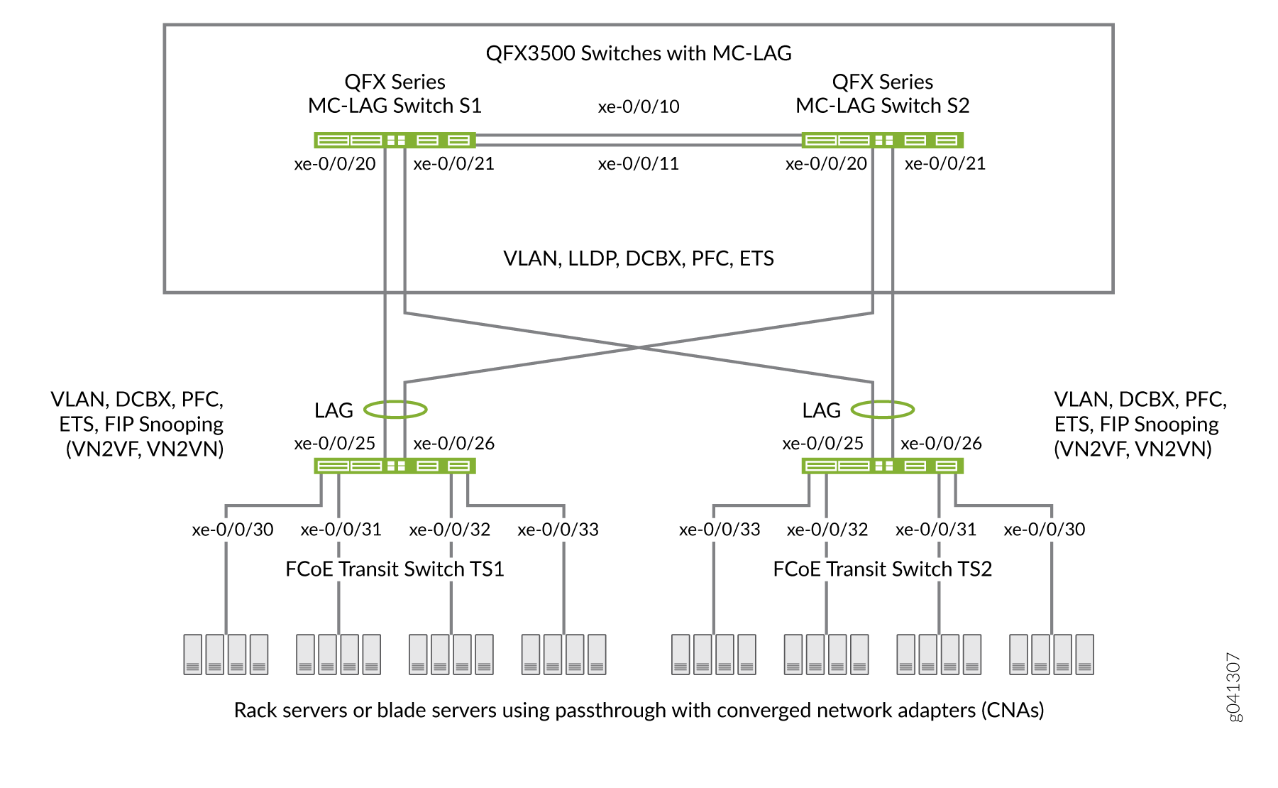
Switches that are not directly connected to FCoE hosts and that act as pass-through transit switches support MC-LAGs for FCoE traffic in an inverted-U network topology. Figure 3 shows an inverted-U topology using QFX3500 switches.
Standalone switches support MC-LAGs. QFabric system Node devices do not support MC-LAGs. Virtual Chassis and mixed-mode Virtual Chassis Fabric (VCF) configurations do not support FCoE. Only pure QFX5100 VCFs (consisting of only QFX5100 switches) support FCoE.
Ports that are part of an FCoE-FC gateway configuration (a virtual FCoE-FC gateway fabric) do not support MC-LAGs. Ports that are members of an MC-LAG act as pass-through transit switch ports.
The following rules and guidelines apply to MC-LAGs when used for FCoE traffic. The rules and guidelines help to ensure the proper handling and lossless transport characteristics required for FCoE traffic.
The two switches that form the MC-LAG (Switches S1 and S2) cannot use ports that are part of an FCoE-FC gateway fabric. The MC-LAG switch ports must be pass-through transit switch ports (used as part of an intermediate transit switch that is not directly connected to FCoE hosts).
MC-LAG Switches S1 and S2 cannot be directly connected to the FCoE hosts.
The two switches that serve as access devices for FCoE hosts (FCoE Transit Switches TS1 and TS2) use standard LAGs to connect to MC-LAG Switches S1 and S2. FCoE Transit Switches TS1 and TS2 can be standalone switches or they can be Node devices in a QFabric system.
Transit Switches TS1 and TS2 must use transit switch ports for the FCoE hosts and for the standard LAGs to MC-LAG Switches S1 and S2.
Enable FIP snooping on the FCoE VLAN on Transit Switches TS1 and TS2. You can configure either VN_Port to VF_Port (VN2VF_Port) FIP snooping or VN_Port to VN_Port (VN2VN_Port) FIP snooping, depending on whether the FCoE hosts need to access targets in the FC SAN (VN2VF_Port FIP snooping) or targets in the Ethernet network (VN2VN_Port FIP snooping).
FIP snooping should be performed at the access edge and is not supported on MC-LAG switches. Do not enable FIP snooping on MC-LAG Switches S1 and S2. (Do not enable FIP snooping on the MC-LAG ports that connect Switches S1 and S2 to Switches TS1 and TS2 or on the LAG ports that connect Switch S1 to S2.)
Note:QFX10000 switches do not support FIP snooping; therefore, they cannot be used as FIP snooping access switches (Transit Switches TS1 and TS2) in this topology.
The CoS configuration must be consistent on the MC-LAG switches. Because MC-LAGs carry no forwarding class or priority information, each MC-LAG switch needs to have the same CoS configuration to support lossless transport. (On each MC-LAG switch, the name, egress queue, and CoS provisioning of each forwarding class must be the same, and the priority-based flow control (PFC) configuration must be the same.)
Transit Switches (Server Access)
The role of FCoE Transit Switches TS1 and TS2 is to connect FCoE hosts in a multihomed fashion to the MC-LAG switches, so Transit Switches TS1 and TS2 act as access switches for the FCoE hosts. (FCoE hosts are directly connected to Transit Switches TS1 and TS2.)
The transit switch configuration depends on whether you want to do VN2VF_Port FIP snooping or VN2VN_Port FIP snooping, and whether the transit switches also have ports configured as part of an FCoE-FC gateway virtual fabric. Ports that a QFX3500 switch uses in an FCoE-FC gateway virtual fabric cannot be included in the transit switch LAG connection to the MC-LAG switches. (Ports cannot belong to both a transit switch and an FCoE-FC gateway; you must use different ports for each mode of operation.)
MC-LAG Switches (FCoE Aggregation)
The role of MC-LAG Switches S1 and S2 is to provide redundant, load-balanced connections between FCoE transit switches. The MC-LAG Switches S1 and S2 act as aggregation switches. FCoE hosts are not directly connected to the MC-LAG switches.
The MC-LAG switch configuration is the same regardless of which type of FIP snooping FCoE Transit Switches TS1 and TS2 perform.
FIP Snooping and FCoE Trusted Ports
To maintain secure access, enable VN2VF_Port FIP snooping or VN2VN_Port FIP snooping at the transit switch access ports connected directly to the FCoE hosts. FIP snooping should be performed at the access edge of the network to prevent unauthorized access. For example, in Figure 3, you enable FIP snooping on the FCoE VLANs on Transit Switches TS1 and TS2 that include the access ports connected to the FCoE hosts.
Do not enable FIP snooping on the switches used to create the MC-LAG. For example, in Figure 3, you would not enable FIP snooping on the FCoE VLANs on Switches S1 and S2.
Configure links between switches as FCoE trusted ports to reduce FIP snooping overhead and ensure that the system performs FIP snooping only at the access edge. In the sample topology, configure the Transit Switch TS1 and TS2 LAG ports connected to the MC-LAG switches as FCoE trusted ports, configure the Switch S1 and S2 MC-LAG ports connected to Switches TS1 and TS2 as FCoE trusted ports, and configure the ports in the LAG that connects Switches S1 to S2 as FCoE trusted ports.
CoS and Data Center Bridging (DCB)
The MC-LAG links do not carry forwarding class or priority information. The following CoS properties must have the same configuration on each MC-LAG switch or on each MC-LAG interface to support lossless transport:
FCoE forwarding class name—For example, the forwarding class for FCoE traffic could use the default
fcoeforwarding class on both MC-LAG switches.FCoE output queue—For example, the
fcoeforwarding class could be mapped to queue 3 on both MC-LAG switches (queue 3 is the default mapping for thefcoeforwarding class).Classifier—The forwarding class for FCoE traffic must be mapped to the same IEEE 802.1p code point on each member interface of the MC-LAG on both MC-LAG switches. For example, the FCoE forwarding class
fcoecould be mapped to IEEE 802.1p code point011(code point011is the default mapping for thefcoeforwarding class).Priority-based flow control (PFC)—PFC must be enabled on the FCoE code point on each MC-LAG switch and applied to each MC-LAG interface using a congestion notification profile.
You must also configure enhanced transmission selection (ETS) on the MC-LAG interfaces to provide sufficient scheduling resources (bandwidth, priority) for lossless transport. The ETS configuration can be different on each MC-LAG switch, as long as enough resources are scheduled to support lossless transport for the expected FCoE traffic.
Link Layer Discovery Protocol (LLDP) and Data Center Bridging Capability Exchange Protocol (DCBX) must be enabled on each MC-LAG member interface (LLDP and DCBX are enabled by default on all interfaces).
As with all other FCoE configurations, FCoE traffic requires a dedicated VLAN that carries only FCoE traffic, and IGMP snooping must be disabled on the FCoE VLAN.
Understanding EVPN-MPLS Interworking with Junos Fusion Enterprise and MC-LAG
You can use Ethernet VPN (EVPN) to extend a Junos Fusion Enterprise or multichassis link aggregation group (MC-LAG) network over an MPLS network to a data center or campus network. With the introduction of this feature, you can now interconnect dispersed campus and data center sites to form a single Layer 2 virtual bridge.
Figure 4 shows a Junos Fusion Enterprise topology with two EX9200 switches that serve as aggregation devices (PE2 and PE3) to which the satellite devices are multihomed. The two aggregation devices use an interchassis link (ICL) and the Inter-Chassis Control Protocol (ICCP) protocol from MC-LAG to connect and maintain the Junos Fusion Enterprise topology. PE1 in the EVPN-MPLS environment interworks with PE2 and PE3 in the Junos Fusion Enterprise with MC-LAG.
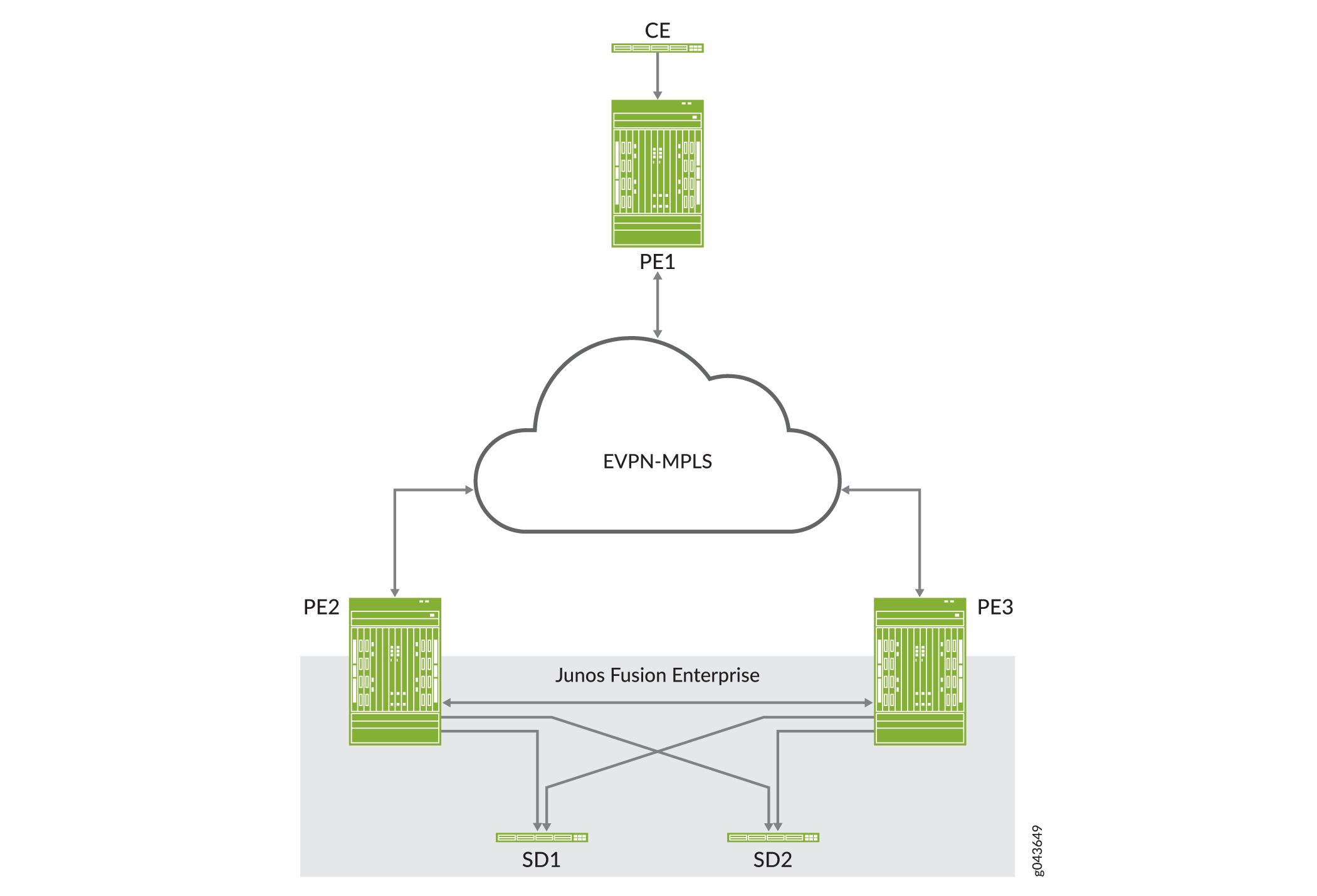
Figure 5 shows an MC-LAG topology in which customer edge (CE) device CE1 is multihomed to PE2 and PE3. PE2 and PE3 use an ICL and the ICCP protocol from MC-LAG to connect and maintain the topology. PE1 in the EVPN-MPLS environment interworks with PE2 and PE3 in the MC-LAG environment.
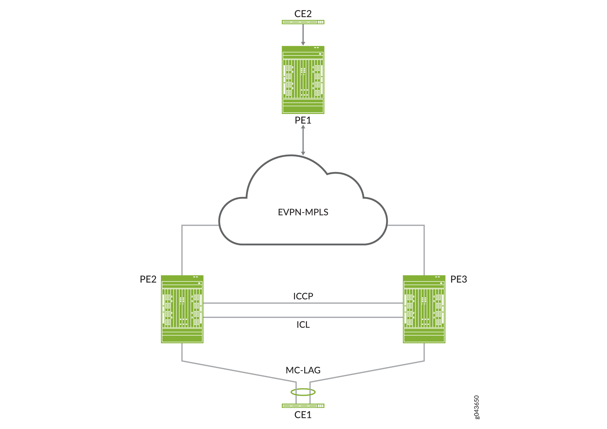
Throughout this topic, Figure 4 and Figure 5 serve as references to illustrate various scenarios and points.
The use cases depicted in Figure 4 and Figure 5 require the configuration of both EVPN multihoming in active-active mode and MC-LAG on PE2 and PE3. EVPN with multihoming active-active and MC-LAG have their own forwarding logic for handling traffic, in particular, broadcast, unknown unicast, and multicast (BUM) traffic. At times, the forwarding logic for EVPN with multihoming active-active and MC-LAG contradict each other and causes issues. This topic describes the issues and how the EVPN-MPLS interworking feature resolves these issues.
Other than the EVPN-MPLS interworking-specific implementations described in this topic, EVPN-MPLS, Junos Fusion Enterprise, and MC-LAG offer the same functionality and function the same as the standalone features.
- Benefits of Using EVPN-MPLS with Junos Fusion Enterprise and MC-LAG
- BUM Traffic Handling
- Split Horizon
- MAC Learning
- Handling Down Link Between Cascade and Uplink Ports in Junos Fusion Enterprise
- Layer 3 Gateway Support
Benefits of Using EVPN-MPLS with Junos Fusion Enterprise and MC-LAG
Use EVPN-MPLS with Junos Fusion Enterprise and MC-LAG to interconnect dispersed campus and data center sites to form a single Layer 2 virtual bridge.
BUM Traffic Handling
In the use cases shown in Figure 4 and Figure 5, PE1, PE2, and PE3 are EVPN peers, and PE2 and PE3 are MC-LAG peers. Both sets of peers exchange control information and forward traffic to each other, which causes issues. Table 2 outlines the issues that arise, and how Juniper Networks resolves the issues in its implementation of the EVPN-MPLS interworking feature.
BUM Traffic Direction |
EVPN Interworking with Junos Fusion Enterprise and MC-LAG Logic |
Issue |
Juniper Networks Implementation Approach |
|---|---|---|---|
North bound (PE2 receives BUM packet from a locally attached single- or dual-homed interfaces). |
PE2 floods BUM packet to the following:
|
Between PE2 and PE3, there are two BUM forwarding paths—the MC-LAG ICL and an EVPN-MPLS path. The multiple forwarding paths result in packet duplication and loops. |
|
South bound (PE1 forwards BUM packet to PE2 and PE3). |
PE2 and PE3 both receive a copy of the BUM packet and flood the packet out of all of their local interfaces, including the ICL. |
PE2 and PE3 both forward the BUM packet out of the ICL, which results in packet duplication and loops. |
Split Horizon
In the use cases shown in Figure 4 and Figure 5, split horizon prevents multiple copies of a BUM packet from being forwarded to a CE device (satellite device). However, the EVPN-MPLS and MC-LAG split horizon implementations contradict each other, which causes an issue. Table 3 explains the issue and how Juniper Networks resolves it in its implementation of the EVPN-MPLS interworking feature.
BUM Traffic Direction |
EVPN Interworking with Junos Fusion Enterprise and MC-LAG Logic |
Issue |
Juniper Networks Implementation Approach |
|---|---|---|---|
North bound (PE2 receives BUM packet from a locally attached dual-homed interface). |
|
The EVPN-MPLS and MC-LAG forwarding logic contradicts each other and can prevent BUM traffic from being forwarded to the ES. |
Support local bias, thereby ignoring the DF and non-DF status of the port for locally switched traffic. |
South bound (PE1 forwards BUM packet to PE2 and PE3). |
Traffic received from PE1 follows the EVPN DF and non-DF forwarding rules for a multihomed ES. |
None. |
Not applicable. |
MAC Learning
EVPN and MC-LAG use the same method for learning MAC addresses—namely, a PE device learns MAC addresses from its local interfaces and synchronizes the addresses to its peers. However, given that both EVPN and MC-LAG are synchronizing the addresses, an issue arises.
Table 4 describes the issue and how the EVPN-MPLS interworking implementation prevents the issue. The use cases shown in Figure 4 and Figure 5 illustrate the issue. In both use cases, PE1, PE2, and PE3 are EVPN peers, and PE2 and PE3 are MC-LAG peers.
MAC Synchronization Use Case |
EVPN Interworking with Junos Fusion Enterprise and MC-LAG Logic |
Issue |
Juniper Networks Implementation Approach |
|---|---|---|---|
MAC addresses learned locally on single- or dual-homed interfaces on PE2 and PE3. |
|
PE2 and PE3 function as both EVPN peers and MC-LAG peers, which result in these devices having multiple MAC synchronization paths. |
|
MAC addresses learned locally on single- or dual-homed interfaces on PE1. |
Between the EVPN peers, MAC addresses are synchronized using the EVPN BGP control plane. |
None. |
Not applicable. |
Handling Down Link Between Cascade and Uplink Ports in Junos Fusion Enterprise
This section applies only to EVPN-MPLS interworking with a Junos Fusion Enterprise.
In the Junos Fusion Enterprise shown in Figure 4, assume that aggregation device PE2 receives a BUM packet from PE1 and that the link between the cascade port on PE2 and the corresponding uplink port on satellite device SD1 is down. Regardless of whether the BUM packet is handled by MC-LAG or EVPN multihoming active-active, the result is the same—the packet is forwarded via the ICL interface to PE3, which forwards it to dual-homed SD1.
To further illustrate how EVPN with multihoming active-active handles this situation with dual-homed SD1, assume that the DF interface resides on PE2 and is associated with the down link and that the non-DF interface resides on PE3. Typically, per EVPN with multihoming active-active forwarding logic, the non-DF interface drops the packet. However, because of the down link associated with the DF interface, PE2 forwards the BUM packet via the ICL to PE3, and the non-DF interface on PE3 forwards the packet to SD1.
Layer 3 Gateway Support
The EVPN-MPLS interworking feature supports the following Layer 3 gateway functionality for extended bridge domains and VLANs:
Integrated routing and bridging (IRB) interfaces to forward traffic between the extended bridge domains or VLANs.
Default Layer 3 gateways to forward traffic from a physical (bare-metal) server in an extended bridge domain or VLAN to a physical server or virtual machine in another extended bridge domain or VLAN.
Understanding the Incremented Values of Statistical Counters for Loop-Free MC-LAG Networks
In an MC-LAG in an active-active bridging domain, the output of the following command displays the MC-LAG color counters to be continuously increasing. This increase in the statistical count is an expected behavior because the MC-LAG color attribute or counter functions as a loop prevention mechanism.
request pfe execute target fpc0 command "show jnh 0 exceptions" |grep color
GOT: mc lag color                       DISC(88)   554712463 144488623417
request pfe execute target fpc0 command "show jnh 0 exceptions" |grep color
GOT: mc lag color                       DISC(88)   554712747 144488664296
The exception table stored in the Packet Forwarding Engine contains a list of counters as displayed in the following example output:
request pfe execute target fpc0 command "show jnh 0 exceptions"
SENT: Ukern command: show jnh 0 exceptions
GOT: Reason                             Type         Packets      Bytes
GOT: ==================================================================
GOT: Ucode Internal
GOT: ----------------------
GOT: mcast stack overflow               DISC(33)           0          0
GOT: sample stack error                 DISC(35)           0          0
GOT: undefined nexthop opcode           DISC(36)           0          0
GOT: internal ucode error               DISC(37)           0          0
GOT: invalid fabric hdr version         DISC(41)           0          0
GOT:
GOT: PFE State Invalid
GOT: ----------------------
GOT: sw error                           DISC(64)   803092438 59795128826
GOT: child ifl nonlocal to pfe          DISC(85)           0          0
GOT: invalid fabric token               DISC(75)         179      42346
GOT: unknown family                     DISC(73)           0          0
GOT: unknown vrf                        DISC(77)           0          0
GOT: iif down                           DISC(87)           0          0
GOT: unknown iif                        DISC( 1)
GOT: invalid stream                     DISC(72)           0          0
GOT: egress pfe unspecified             DISC(19)       10889    1536998
GOT: invalid L2 token                   DISC(86)          26       1224
GOT: mc lag color                       DISC(88)   554693648
144486028726<<<<<<<<<<<<<<<<<<<<<<<<
GOT: dest interface non-local to pfe    DISC(27)  10939253797 2078273071209
GOT: invalid inline-svcs state          DISC(90)           0          0
GOT: nh id out of range                 DISC(93)           0          0
GOT: invalid encap                      DISC(96)           0          0
GOT: replication attempt on empty irb   DISC(97)           0          0
GOT: invalid selector entry             DISC(98)           0          0
GOT:
GOT:
GOT: Packet Exceptions
GOT: ----------------------
GOT: bad ipv4 hdr checksum              DISC( 2)
GOT: non-IPv4 layer3 tunnel             DISC( 4)           0          0
GOT: GRE unsupported flags              DISC( 5)           0          0
GOT: tunnel pkt too short               DISC( 6)           0          0
GOT: tunnel hdr too long                DISC( 7)           0          0
GOT: bad IPv6 options pkt               DISC( 9)           0          0
GOT: bad IP hdr                         DISC(11)           0          0
GOT: bad IP pkt len                     DISC(12)           0          0
GOT: L4 len too short                   DISC(13)
GOT: invalid TCP fragment               DISC(14)           0          0
GOT: mtu exceeded                       DISC(21)           0          0
GOT: frag needed but DF set             DISC(22)           0          0
GOT: ttl expired                        PUNT( 1)           9        769
GOT: IP options                         PUNT( 2)          16        512
GOT: xlated l2pt                        PUNT(14)           0          0
GOT: control pkt punt via ucode         PUNT( 4)           0          0
GOT: frame format error                 DISC( 0)
GOT: tunnel hdr needs reassembly        PUNT( 8)           0          0
GOT: GRE key mismatch                   DISC(76)           0          0
GOT: my-mac check failed                DISC(28)
GOT: frame relay type unsupported       DISC(38)           0          0
GOT: IGMP snooping control packet       PUNT(12)           0          0
GOT: bad CLNP hdr                       DISC(43)           0          0
GOT: bad CLNP hdr checksum              DISC(44)           0          0
GOT: Tunnel keepalives                  PUNT(58)           0          0
GOT:
GOT:
GOT: Bridging
GOT: ----------------------
GOT: lt unknown ucast                   DISC(84)           0          0
GOT: dmac miss                          DISC(15)           0          0
GOT: mac learn limit exceeded           DISC(17)           0          0
GOT: static mac on unexpected iif       DISC(18)           0          0
GOT: no local switching                 DISC(20)           0          0
GOT: bridge ucast split horizon         DISC(26)       39458   13232394
GOT: mcast smac on bridged iif          DISC(24)        1263     200152
GOT: bridge pkt punt                    PUNT( 7)           0          0
GOT: iif STP blocked                    DISC( 3)
GOT: oif STP blocked                    DISC(31)
GOT: vlan id out of oif's range         DISC(32)
GOT: mlp pkt                            PUNT(11)    15188054  440453569
GOT: input trunk vlan lookup failed     DISC(91)           0          0
GOT: output trunk vlan lookup failed    DISC(92)           0          0
GOT: LSI/VT vlan validation failed      DISC(94)           0          0
GOT:
GOT:
GOT: Firewall
GOT: ----------------------
GOT: mac firewall                       DISC(78)
GOT: firewall discard                   DISC(67)           0          0
GOT: tcam miss                          DISC(16)           0          0
GOT: firewall reject                    PUNT(36)      155559   59137563
GOT: firewall send to host              PUNT(54)           0          0
GOT: firewall send to host for NAT      PUNT(59)           0          0
GOT:
GOT:
GOT: Routing
GOT: ----------------------
GOT: discard route                      DISC(66)     1577352   82845749
GOT: dsc ifl discard route              DISC(95)           0          0
GOT: hold route                         DISC(70)       21130    1073961
GOT: mcast rpf mismatch                 DISC( 8)           0          0
GOT: resolve route                      PUNT(33)        2858     154202
GOT: control pkt punt via nh            PUNT(34)    51807272 5283911584
GOT: host route                         PUNT(32)    23473304 1370843994
GOT: ICMP redirect                      PUNT( 3)           0          0
GOT: mcast host copy                    PUNT( 6)           0          0
GOT: reject route                       PUNT(40)        1663     289278
GOT: link-layer-bcast-inet-check        DISC(99)           0          0
GOT:
Consider a sample deployment in which two provider edge (PE)
routers, PE1 and PE2, are connected with an aggregated Ethernet interface, ae0. respectively. Multichassis link aggregation groups (MC-LAGs)
are used between PE1 and PE2 to form a logical LAG interface between
the two controllers. PE1 and PE2 in an MC-LAG use an interchassis
control link-protection link (ICL-PL) to replicate forwarding information
across the peers.
Inter-Chassis Control Protocol (ICCP) messages are sent between the two PE devices. In this example, you configure an MC-LAG across two routers, consisting of two aggregated Ethernet interfaces, an interchassis control link-protection link (ICL-PL), multichassis protection link for the ICL-PL, and ICCP for the peers hosting the MC-LAG.
The PE1 router is connected using another aggregated Ethernet
interface, ae3, to a host, H1, and to another MC-LAG host
called C1. MC-LAG is enabled on the ae3 interface.
Traffic received on PE1 from MC-LAG C1 can be flooded over the
ICL to reach PE2. When the packets arrive at PE2, they can be flooded
back to MC- LAG C1. Traffic sent by the single-homed host H1 can be
flooded to MC-LAG C1 and the ICL on PE1. When PE2 receives such traffic
from ICL, it can be again flooded to MC-LAG C1. To protect the MC-LAG
topology from such loops, the MC-LAG color capability is implemented.
This functionality is applied on the ingress of the ICL link. Therefore,
when PE2 receives a packet from PE1, it sets the MC-LAG color as active
or turns it on. When PE2 requires to flood the packet towards the
MC-LAG link, it verifies whether the MC-LAG color bit is set or tagged
as on. If the color is set, it drops the packet on the egress interface
of MC-LAG ae3 member link interfaces and the mc-lag color counter in the jnh exceptions is incremented.
Such a behavior of increase in counter value is an expected condition in an MC-LAG configured in an active/active bridging domain and when any form of traffic that needs to be flooded, such as ARP broadcast or multicast traffic, traverses the network.
Every VLAN might drop some packets to prevent loops and such a drop of packets might not be specific to a VLAN.
Sometimes, on both MC LAGs of the MX Series routers, you might notice that the counter increases on FPC0 and FPC2, but it does not increase on FPC2 as illustrated in the following sample output:
request pfe execute target fpc0 command "show jnh 0 exceptions" |grep color
GOT: mc lag color                       DISC(88)   558477875 144977739683
request pfe execute target fpc1 command "show jnh 0 exceptions" |grep color
GOT: mc lag color                       DISC(88)           0          0
request pfe execute target fpc2 command "show jnh 0 exceptions" |grep color
GOT: mc lag color                       DISC(88)   518499257 119130527834
This behavior occurs because on an MX Series router with a 16-port
10-Gigabit Ethernet MPC (16x10GE 3D MPC), there are four Packet Forwarding
Engines for each MPC. If you examine one Packet Forwarding Engine
in FPC 0, 1, and 2, PFE1 in FPC1 does not have any interfaces which
are member of MC-LAG. It might contain interfaces in other aggregated
Ethernet interfaces that are are not part of MC-LAG. Therefore, to
obtain the correct counter statistics, you must examine the other
Packet Forwarding Engines by entering the request pfe execute
target fpc0 command "show jnh X exceptions" |grep color command
where X can be 0, 1, 2, or 3.
When the counter named dest interface non-local
to pfe is increasing, it is a desired behavior when
aggregated Ethernet interfaces are split over more than one FPC.
Consider an example in which an ae5 interface contains
the following member links: xe-0/1/0 on (FPC0) and xe-1/1/0 (FPC1) Based on the hash algorithm, traffic must
be split between these two links. The hash algorithm is applied on
the ingress FPC and performs an operation where it marks each packet
through which FPC must be forwarded (FPC0 or FPC1). Then the packet
is sent to the fabric. From the fabric, all of traffic is sent to
both FPCs 0 and 1. On FPC0, the microkernel analyzes the packet and
determines whether the packet needs to be forwarded by the local
interface (local to pfe) or whether this packet has already been forwarded
through FPC1 (non-local to pfe). If the packet has been already forwarded,
the packet is dropped and the non-local to pfe counter is incremented.
Enhanced Convergence
When enhanced convergence is enabled, the MAC address, ARP or ND entries learned over the MC-AE interfaces are programmed in the forwarding table with the MC-AE link as the primary next-hop and with ICL as the backup next-hop. With this enhancement, during an MC-AE link failure or restoration, only the next-hop information in the forwarding table is updated and there is no flushing and relearning of the MAC address, ARP or ND entry. This process improves traffic convergence during MC-AE link failure or restoration because the convergence involves only next-hop repair in the forwarding plane, with the traffic being fast rerouted from the MC-AE link to the ICL.
If you have configured an IRB interface over an MC-AE interface that has enhanced convergences enabled, then you must configure enhanced convergence on the IRB interface as well. Enhanced convergence must be enabled for both Layer 2 and Layer 3 interfaces.
IPv6 Neighbor Discovery Protocol
Neighbor Discovery Protocol (NDP) is an IPv6 protocol that enables nodes on the same link to advertise their existence to their neighbors and to learn about the existence of their neighbors. NDP is built on top of Internet Control Message Protocol version 6 (ICMPv6). It replaces the following IPv4 protocols: Router Discovery (RDISC), Address Resolution Protocol (ARP), and ICMPv4 redirect.
You can use NDP in a multichassis link aggregation group (MC-LAG) active-active configuration on switches.
NDP on MC-LAGs uses the following message types:
-
Neighbor solicitation (NS)—Messages used for address resolution and to test reachability of neighbors.
A host can verify that its address is unique by sending a neighbor solicitation message destined to the new address. If the host receives a neighbor advertisement in reply, the address is a duplicate.
-
Neighbor advertisement (NA)—Messages used for address resolution and to test reachability of neighbors. Neighbor advertisements are sent in response to neighbor solicitation messages.
Platform-Specific Behavior
Use Feature Explorer to confirm the platform and release support for specific features.
Use the following table to review the platform-specific behaviors for your platform.
Platform-Specific MC-LAG Behavior
| Platform | Difference |
|---|---|
|
ACX7000 family of cloud metro routers |
The routers do not support the following:
|
|
The routers do not support the following configuration statements:
|
|
|
The following limitations apply to the routers:
|
|
|
QFX5000 Switches |
Only pure QFX5100 VCFs (consisting of only QFX5100 switches) support FCoE. |
|
QFX10000 Switches |
QFX10000 switches do not support FIP snooping, so they cannot be used as FIP snooping access switches. |
Change History Table
Feature support is determined by the platform and release you are using. Use Feature Explorer to determine if a feature is supported on your platform.
enhanced-convergence
and arp-enhanced-scale statements.enhanced-convergence statement.