In-band Zero Touch Provisioning
To see which platforms support In-band Zero Touch Provisioning, go to Feature Explorer. In the Explore Features section of the Feature Explorer page, select All Features. In the Features Grouped by Feature Family box, select Zero Touch Provisioning. You can also type the name of the feature in the Search for Features edit box. See the Release History Table at the end of this topic for more details of how ZTP support has expanded.
Benefits
-
Saves money on overhead costs associated with out-of-band management.
-
Simplifies provisioning process for Day 0 devices.
-
Uses existing Link Level Discovery Protocol (LLDP) telemetry data to detect the state and interfaces of Day 0 devices.
In-band ZTP Overview
In-band zero-touch provisioning (ZTP) simplifies the onboarding process for newly connected devices in an IP fabric. In-band managemend reduces the overhead costs of using an out-of-band network to manage your newly added Day 0 downstream devices. Instead of using an out-of-band network, you use your already provisioned Day 1 upstream devices to provide Layer 3 network connectivity to your Day 0 downstream devices.
By default, a factory configuration running on a Day 0 downstream device only provides Layer 2 connectivity. All network interfaces configured between Day 1 upstream devices and Day 0 downstream devices are part of the default VLAN and have a VLAN ID of 1. The factory default configuration also includes a DHCP client configuration on an integrated routing and bridging (IRB) interface.
When the Day 0 downstream devices are powered on, they start sending Dynamic Host Control Protocol (DHCP) discovery request messages to obtain Layer 3 connectivity. Before your Day 1 upstream devices can provide Layer 3 connectivity to your Day 0 downstream devices, your Day 1 upstream devices need to be able to detect the Day 0 downstream device network interfaces.
To detect these network interfaces, such as dynamic link aggregation group (LAG)
interfaces, you need to enable the in-band statement at the
 [edit system
                        services]
hierarchy on your Day 1 upstream devices. With this statement enabled, the Day 1
upstream devices can invoke a Python daemon, which uses Link-Level Layer Discovery
Protocol (LLDP) telemetry data for monitoring.
When the Python daemon detects a dynamic (LAG) interface between a Day 1 upstream
device and a Day 0 downstream device, the Python daemon configures the LAG interface
to be up by enabling the force-up statement at the [edit
interfaces interface-name aggregated-ether-options
lacp] hierarchy. The Python daemon then converts the dynamic LAG
interface to a static LAG interface.
The Python daemon also commits a local DHCP server configuration on your Day 1 upstream device to provide Layer 3 connectivity to the Day 0 downstream device. The Python daemon derives the Layer 3 IP address from the DHCP pool that is configured as part of the DHCP server configuration. With Layer 3 connectivity, the Day 0 downstream devices can connect to a phone-home server and proceed with ZTP.
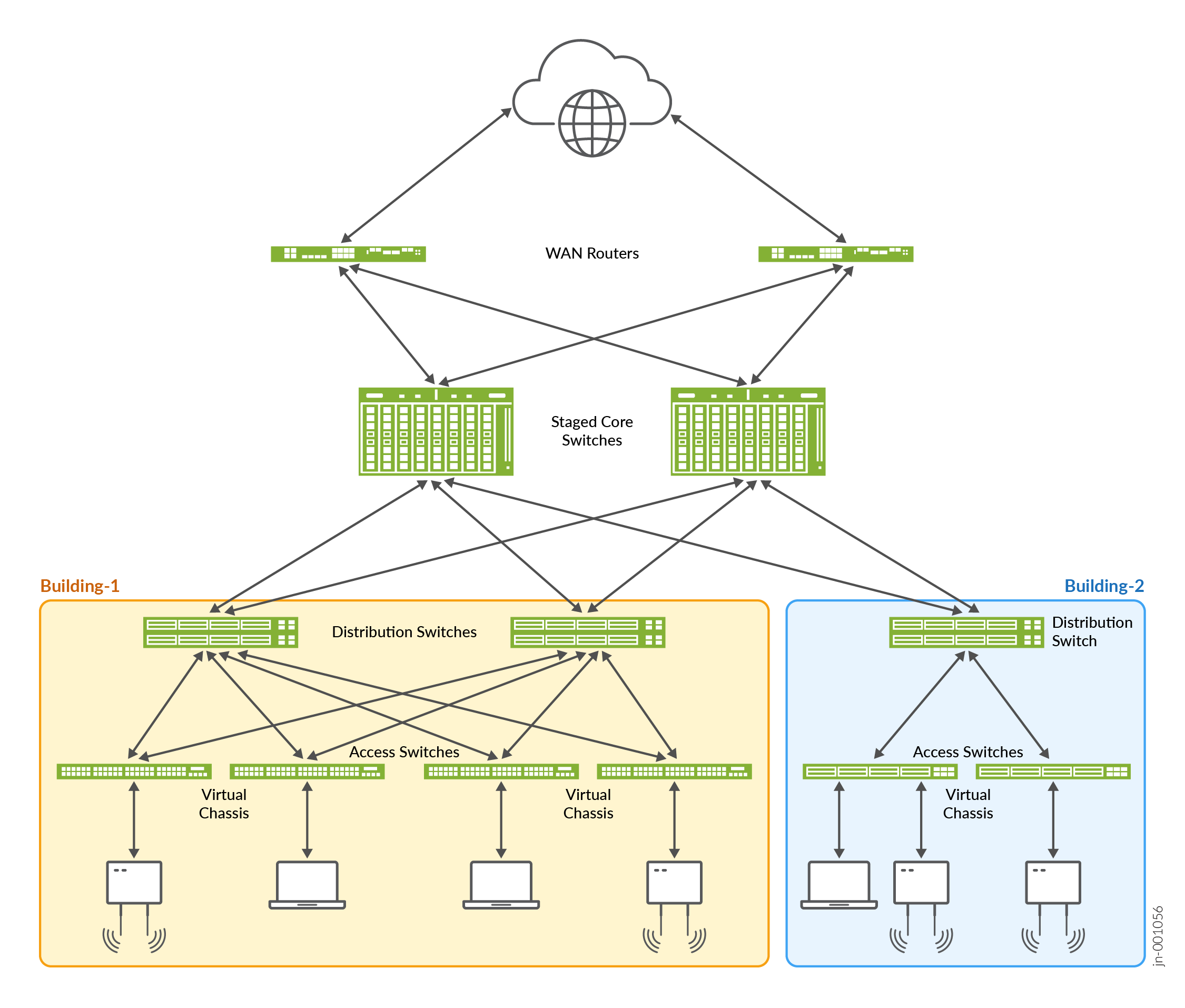
Figure 1 illustrates an IP fabric where Day 1 upstream core devices are already provisioned and are connected to the cloud through dual-homed WAN routers.

Adding Distribution Devices to an IP Fabric
In order for the Day 1 upstream core devices to perform in-band ZTP on your Day 0
downstream distribution devices, you need to enable theinband-ztp
statement at the [edit system services] CLI hierarchy on your Day 1
upstream core devices.
For example:
[edit]
set system services inband-ztp management-vlan-id 10
set system services inband-ztp name-server 10.1.12.0/24
Adding Access Devices to an IP Fabric
In order for the Day 1 upstream distribution devices to perform in-band ZTP on your
Day 0 downstream access devices, you need to enable theinband-ztp
statement at the [edit system services] CLI hierarchy on your Day 1
upstream distribution devices.
For example:
[edit]
set system services inband-ztp management-vlan-id 10
set system services inband-ztp name-server 10.1.12.0/24
