
Binding SID (BSID) for Static SRv6 TE Tunnels
The SRv6 binding SID (BSID) is an instruction to a transit router to steer an incoming SRv6 packet down a traffic-engineered path. This is achieved by pushing a new IPv6 header onto the packet, potentially with a new SRH, containing an SRv6 SID stack that defines the TE path. This has many uses regarding network stability, such as enabling hardware with shallow SID stack capabilities to send traffic down a large TE path, or helping to isolate or decouple different source-routed domains. The BSID allows the segregation of the network into multiple TE tunnels, each comprising its own SID stack and compute model. This feature enables the static SRv6 TE tunnels with transit functionality.
Binding SID Overview
When an ingress router is configured with Segment Routing over IPv6 with Traffic Engineering (SRv6-TE) feature, an incoming service payload is encapsulated in an IPv6 tunnel, optionally with an SRH that directs the traffic to take a specific TE path in the network, based on the configured SRv6 policy.
Often the SID stack can grow in size resulting in packet overhead. Some devices in the network might not be able to write, pop, or process packets with large SRv6 SID stacks. In addition to this, it might sometimes be impractical for the ingress node to encode the whole stack for inter-domain networks, because the ingress router might not have knowledge of remote topologies and SIDs in its Traffic Engineering Database (TED). Leaking this information between routing domains comes with its own trade-offs, including overhead and convergence issues. If there is a transit MPLS domain, the labels and SRv6 SIDs might result in a lot of overhead as well.
The SRv6 binding SID (BSID) provides a solution by segregating an end-to-end path into multiple TE tunnels. Binding SIDs are a segment type where one incoming SID acts as an instruction to encapsulate the existing IPv6 transport header with a brand new IPv6 header that contains a stack of outgoing SIDs.
A transit router, configured with a binding SID, gains the ability to act as an ingress router for a shorter TE tunnel on the larger path. This is formally described as steering the incoming packet into an SR policy. When a packet is steered into an SR policy with a BSID, the node that owns the BSID expands that SID into the full segment list of the associated policy.
In a binding SID implementation, an ingress router no longer needs to push the entire end-to-end stack of SIDs onto a packet. Instead, it is enough to strategically push a smaller number of binding SIDs onto a packet. Therefore, rather than having full knowledge of the entire wider network, the ingress node only needs knowledge of the binding SIDs in the network to create a TE path. The wider network convergence is taken care of at the transit node that is provisioned with the binding SID.
Remote transit routers remove these SIDs from the IPv6 Destination Address (DA) field, and push the additional TE segments in a new IPv6 header. In this respect, each TE tunnel on the path can be comprised of its own stack, its own choice of whether or not to use backup paths, and its own compute model.
When a transit node, configured with a binding SID, receives an incoming packet with its IPv6 DA matching the BSID through longest prefix match, the transit router first pops the binding SID. In the case of classic SRv6, this involves writing the next address in the SRH to the IPv6 DA. In the case of SRv6 with micro-SIDs, this involves popping the active micro-SID from the IPv6 DA, and then either rewriting the IPv6 DA as appropriate, or writing the next address in the SRH to the IPv6 DA. The transit router then encapsulates the packet with a new IPv6 header that contains the SIDs for the onward TE path. In the case of classic SRv6, this IPv6 header will likely contain an SRH with additional segments. In the case of SRv6 with micro-SIDs, the DA in the new IPv6 header might be enough to carry all the required SIDs. If not, the new IPv6 header can carry a new SRH. This results in a comparatively reduced stack size at the ingress node, because the additional SIDs are written to the packet by the transit router.
Four types of SRv6 binding SIDs are supported:
-
Classic SRv6 binding SID
- END.B6.Encaps: When the transit node, configured with a binding SID, processes a matching packet, it always encapsulates the outgoing packet with a new IPv6 header and SRH that contains the SID stack of the new TE tunnel. This is a non-reduced mode implementation and thus the address in the new IPv6 DA is also written to the SRH.
- END.B6.Encaps.Red: This is the reduced mode implementation where the first SRv6 address in the stack is only written to the DA of the new IPv6 address and not to the SRH. When the transit node, configured with a binding SID, processes a matching packet, it encapsulates the outgoing packet with a new IPv6 header and optionally, an SRH. There may not be an SRH for the outer IPv6 encapsulation if the SRv6 policy only contains one SID. This is the default mode.
- Micro SRv6 binding SID
-
END.B6.Encaps with Next-C-SID: When the transit node, configured with a binding SID, processes a matching packet, it encapsulates the outgoing packet with a new IPv6 header and SRH that contains the SID stack of the new TE tunnel. This is a non-reduced mode implementation and thus the DA in the new IPv6 header is also written in the SRH. This is true even if the micro-SID stack can be contained inside one single IPv6 DA.
-
END.B6.Encaps.Red with Next-C-SID: When the transit node, configured with a binding SID, processes a matching packet, it encapsulates the outgoing packet with a new IPv6 header and optionally, an SRH. The DA of the outer IPv6 header is not added to the SRH. If the SRv6 policy contains a stack of micro-SIDs that can be written to one single IPv6 DA, or if the SRv6 policy only contains one SID, then the packet will not contain an SRH. This is the default mode.
-
The binding SID configuration is performed on the transit router. You define the binding SID directly inside the SR policy that it is bound to. This immediately associates that binding SID with the correct TE path.
The following options are available to configure binding SID under the [edit
protocols source-packet-routing source-routing-path] hierarchy. You can either
configure a classic SRv6 binding SID or a micro SRv6 binding SID. The locator must be
preconfigured under the [edit routing-options source-packet-routing srv6
locator] hierarchy. The static SID is mandatory and must be from within the local
micro SID static SID range defined for the block under the [edit routing-options
source-packet-routing srv6 block] hierarchy.
- You can either configure a classic SRv6 binding SID or a micro SRv6 binding
SID:
set protocols source-packet-routing source-routing-path path_name srv6-binding-sid | micro-srv6-binding-sid locator loc_name static_sid
set protocols source-packet-routing source-routing-path path_name srv6-binding-sid | micro-srv6-binding-sid locator loc_name no-reduced-srh
When configuring the classic SRv6 SID, the entire classic BSID must be provided along with the locator name. For example:
set protocols source-packet-routing source-routing-path to_PE srv6-binding-sid locator classic-srv6-loc 2001:db8:a1:2:1::
When configuring the micro SRv6 SID, only the functional part needs to be provided along with the locator name. For example:
set protocols source-packet-routing source-routing-path to-PE2 micro-srv6-binding-sid locator uNSID20 0xfc58
- The ingress router is configured with the first segment list hop as the binding SID. In
the configuration snippet below,
5f00:0:200:fc58::is the micro binding SID configured on the transit router. Notice that the configuration does not mention that this is a binding SID, because this information is not important to the ingress router. The SRv6 micro service SID5f00:0:2020::is the last hop in the segment list. For example:set protocols source-packet-routing segment-list sl_to_PE2 p2 micro-srv6-sid 5f00:0:200:fc58:: set protocols source-packet-routing segment-list sl_to_PE2 pe2 micro-srv6-sid 5f00:0:2020::
- The feature supports multiple transit routers with binding SID in a TE path. The ingress
router must be configured with every binding SID transit router as a segment list hop. In
the example below P2 and P4 are two transit routers on the TE path with binding SID
configured.
set protocols source-packet-routing segment-list sl_to_PE2 p2 micro-srv6-sid 5f00:0:200:fc58::
set protocols source-packet-routing segment-list sl_to_PE2 p4 micro-srv6-sid 5f00:0:400:fc68::
set protocols source-packet-routing segment-list sl_to_PE2 pe2 micro-srv6-sid 5f00:0:2020::
-
You can enable traces specific to SRv6 binding SID.
set protocols source-packet-routing traceoptions flag srv6-binding-sid
Benefits of Binding SRv6 SID
-
The Ingress node requires only a subset of TE database of other domains.
-
Convergence is taken care of at each transit nodes provisioned with binding SID
-
You can deploy a cross-data plane switch (SRv6 to MPLS) by configuring a binding SID to pop the outer IPv6 header, and then push one or more outgoing MPLS labels.
Limitations and Caveats
- Endpoint behavior flavors like USD, USP or PSP associated with an SRv6 BSID are not supported for binding SID.
- No support for insert mode SRv6 binding SID endpoint behaviors such as END.B6.Insert, END.B6.Insert with Next-C-SID and END.BM.
- Only default length SID structure is supported for END.B6.Encaps with Next-C-SID and END.B6.Encaps.Red with Next-C-SID (BL: 32, NL: 16, FL:16, AL:64).
-
A change in locator configuration requires a routing restart for the change to take effect.
-
Support for transport class and colored SR-TE only.
-
Support for BGP-LS distribution of SRv6 classic binding SID and micro binding SID.
-
Support for binding SID configuration with its segment list ending at egress node of the SRv6 tunnel.
See Also
Configure Binding SID (BSID) for Static SRv6 TE with Micro-SIDs
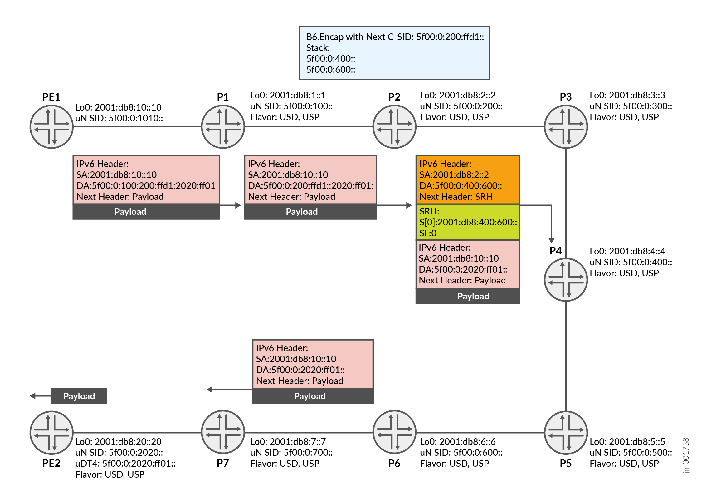
100), P2's SRv6 micro BSID (200:ffd1) and
PE2's micro service SID (2020:ff01). In total, PE1 has written five micro-SIDs to the IPv6 DA. In practice, some platforms may only be able to write a limited number of SRv6 micro-SIDs to the IPv6 DA, and therefore this SID stack would require an SRH. The implementation varies between platforms. However, the general behavior described in this example is universal.
When P2, configured with a binding SID, receives the packet matching theEND.B6.Encaps with Next-C-SID or END.B6.Encaps.Red with
NEXT-C-SID local SID through longest prefix match, it first pops its binding SID from
the IPv6 DA, and rewrites the IPv6 DA accordingly. P2 then it encpasulates the outgoing packet
with a segment list comprising P4's SRv6 micro-SID and P6's SRv6 micro-SID in the DA of the new
IPv6 header. This new header may or may not contain an SRH, depending on whether the SID is
configured for reduced or non-reduced mode behavior. P6 is the egress router for the new tunnel that began at P2. When the packet arrives at P6, the outer header is decapsulated along with any SRH. The packet is then forwarded to the egress node PE2 where the inner header is decapsulated and resolved using a longest prefix match. The payload is then forwarded to its destination.
Verify Binding SID Configuration
Purpose
These verification commands trace the lifecycle of a Binding SID (BSID) and an SR-TE Policy through the router's control plane.
Action
-
Verify the binding SID allocation from the locator on the transit router using the
show srv6 locator loc_namecommand. In the output below, you can observe the BSID is allocated from the locator prefix. The SID behavior is configured as End.B6.Encaps with Next-CSID, which means upon receiving a matching packet, the router will encapsulate it with an SRH.user@P2> show srv6 locator uNSID20 Locator: uNSID20 Locator prefix: 5f00:0:1010::, Locator length: 48 Block length: 32, Node length: 16 Function length: 16, Argument length: 0 Micro SID Locator, Flavor [ USD ] Micro SID Block Name: adjblock1 SID SID-Owner SID-Type SID-Behavior 5f00:0:200:fc58:: SRTE STATIC End.B6.Encaps with NEXT-CSID
-
Verify the SRv6 binding SID information in the SR-TE database of the transit router using the
show spring-traffic-engineering srv6-binding-sid databasecommand. In the output below, you can verify the BSID is installed in the SR-TE policy database and it is mapped with the configured policy and tunnel.user@P2> show spring-traffic-engineering srv6-binding-sid database * = Allocated SRv6 Binding SID Policy Ep-Bhv = Endpoint-Behavior Endpoint Behaviors 14 = End.B6.Encaps 93 = End.B6.Encaps with NEXT-CSID 27 = End.B6.Encaps.Red 94 = End.B6.Encaps.Red with NEXT-CSID SRv6 Binding SID Ep-Bhv Policy Tunnels 5f00:0:200:fc58::/64 93 * 2001:db8:20::20-4001 to-PE2
-
Verify the SR-TE ingress LSP detail for the source routing path on the transit router using the
show spring-traffic-engineering lsp detail name
       path_name
. In the output below, you can verify the LSP state, BSID association and the actual segment list (SR-ERO). This implies that the router is aware of the policy path and segments used for traffic steering.user@P2> show spring-traffic-engineering lsp detail name to-PE2 E = Entropy-label Capability Name: to-PE2 Tunnel-source: Static configuration Tunnel Forward Type: SRV6 To: 2001:db8:20::20-4001<c6> From: 2001:db8:1::1 SRv6 Binding SID: 5f00:0:200:fc58::, State: Allocated Locator: uNSID20 Endpoint Behavior: End.B6.Encaps with NEXT-CSID (93) SSTLV: BL:32, NL:16, FL:16, AL:0 State: Up Path: sl_to_PE2 Path Status: Up Outgoing interface: NA Auto-translate status: Disabled Auto-translate result: N/A Compute Status:Disabled , Compute Result:N/A , Compute-Profile Name:N/A BFD status: N/A BFD name: N/A BFD remote-discriminator: N/A Segment ID : 128 ERO Valid: true SR-ERO hop count: 2 Hop 1 (Strict): NAI: None SID type: Micro SRv6 SID, Value: 5f00:0:400:: SSTLV: BL: 32, NL: 16, FL: 0, AL: 80 Hop 2 (Strict): NAI: None SID type: Micro SRv6 SID, Value: 5f00:0:600:: SSTLV: BL: 32, NL: 16, FL: 0, AL: 80 Total displayed LSPs: 1 (Up: 1, Down: 0, Initializing: 0) -
Verify SR-TE router information for the binding SID and micro service SID on the transit router using the
show spring-traffic-engineering route detailcommand. The output below confirms there are routes pointing to the BSID and to the endpoint. It also shows the associated LSP forwarding.user@P2> show spring-traffic-engineering route detail To : 5f00:0:200:fc58::/64 SRv6 Binding SID Endpoint Behavior: End.B6.Encaps with NEXT-CSID (93) SSTLV: BL:32, NL:16, FL:16, AL:0 Distinguisher : 0 Tunnel-source : Static configuration Route Nexthop Type: Indirect Route Metric2 : 30 Route Forward Type : SRV6, Encap Mode : Non-Reduced SRH LSP Name: to-PE2 SR Preference : 100, SR Preference Override : 100 Metric : 1 State : Up LSP ID : 4 LSP Path Name: sl_to_PE2 LSP Path Bandwidth: 1 Weight: 1, Balance: 1 SR-ERO hop count: 2 Hop 1 (Strict): NAI: None SID type: Micro SRv6 SID, Value: 5f00:0:400:: SSTLV: BL: 32, NL: 16, FL: 0, AL: 80 Hop 2 (Strict): NAI: None SID type: Micro SRv6 SID, Value: 5f00:0:600:: SSTLV: BL: 32, NL: 16, FL: 0, AL: 80 To : 2001:db8:20::20-4001<c6> Distinguisher : 0 Tunnel-source : Static configuration Route Nexthop Type: Indirect Route Metric2 : 30 Route Forward Type : SRV6, Encap Mode : Non-Reduced SRH Using Transport class : true LSP Name: to-PE2 SR Preference : 100, SR Preference Override : 100 Metric : 1 State : Up LSP ID : 4 LSP Path Name: sl_to_PE2 LSP Path Bandwidth: 1 Weight: 1, Balance: 1 SR-ERO hop count: 2 Hop 1 (Strict): NAI: None SID type: Micro SRv6 SID, Value: 5f00:0:400:: SSTLV: BL: 32, NL: 16, FL: 0, AL: 80 Hop 2 (Strict): NAI: None SID type: Micro SRv6 SID, Value: 5f00:0:600:: SSTLV: BL: 32, NL: 16, FL: 0, AL: 80 -
Verify the SRv6 policy information in the traffic engineering database on the transit router using the
show ted spring-te-policy extensivecommand. The output below shows the origin, color and segment list for the SRv6 policy.user@P2> show ted spring-te-policy extensive TED database: 1 ISIS nodes 0 INET nodes 0 INET6 nodes NodeID: R1.00(1.1.1.1)(2001:db8:1::1) Type: RtrAge: 194 secs Protocol: SPRING-TE(0) Color: 4001, Endpoint: 2001:db8:20::20 Candidate Path Name: to-PE2, Flags: 0x8 Origin: 3, Origin Address: 2001:db8:1::1 , AS: 0, Discriminator: 0 Preference: 100, Priority: 128 BSID Flags: 0x1, SRV6 BSID: 5f00:0:200:fc58::, SRV6 SPECIFIED BSID: 5f00:0:200:fc58:: BSID Endpoint Behavior: 93, Flags: 0x0, Algo: 0 SSTLV: BL:32, NL:16, FL:16, AL:0 Number of Segments: 2 Segments: SRV6 SID: 5f00:0:400::, Segment Flags: 0x7 SID Structure: LB Length - 32, LN Length - 16, Function Length - 0, Argument Length - 80 SRV6 SID: 5f00:0:600::, Segment Flags: 0xf SID Structure: LB Length - 32, LN Length - 16, Function Length - 0, Argument Length - 80 -
Verify the SR-TE ingress LSP detail for the source routing path on the ingress router using the
show spring-traffic-engineering lsp detail name
              path_name
command. In the output below,Hop 1is the BSID that the ingress pushes in the new IPv6 header DA, with or without SRH.Hop 2is the service micro-SID.user@PE1> show spring-traffic-engineering lsp detail name to-PE2 E = Entropy-label Capability Name: to-PE2 Tunnel-source: Static configuration Tunnel Forward Type: SRV6 To: 2001:db8:20::20-4001<c6> From: 2001:db8:10::10 State: Up Path: sl_to_PE2 Path Status: Up Outgoing interface: NA Auto-translate status: Disabled Auto-translate result: N/A Compute Status:Disabled , Compute Result:N/A , Compute-Profile Name:N/A BFD status: N/A BFD name: N/A BFD remote-discriminator: N/A Segment ID : 128 ERO Valid: true SR-ERO hop count: 2 Hop 1 (Strict): NAI: None SID type: Micro SRv6 SID, Value: 5f00:0:200:fc58:: SSTLV: BL: 32, NL: 16, FL: 16, AL: 64 Hop 2 (Strict): NAI: None SID type: Micro SRv6 SID, Value: 5f00:0:2020:: SSTLV: BL: 32, NL: 16, FL: 0, AL: 80 Total displayed LSPs: 1 (Up: 1, Down: 0, Initializing: 0) -
Verify the traffic flow through the SR-TE path. Note that
2001:db8:1000::100,2001:db8:1000:200and2001:db8:1000::2020are ingress interface IPs for routers P1, P2 and PE2.2001:db8:6::6is the loopback address for P6 router.user@PE1> traceroute srv6 spring-te micro-sids-stack usids [ 5f00:0:2020:: 5f00:0:200:fc58:: 5f00:0:100:: ] nexthop-interface xe-0/0/0:0.0 nexthop-address 2001:db8:f500:20c:4600 traceroute to destination 5f00:0:100:200:fc58:2020::, from source 2001:db8:10::10, 64 hops max, retries 3 1 2001:db8:1000::100 21.677 ms 21.932 ms 22.347 ms DA: 5f00:0:100:200:fc58:2020:: 2 2001:db8:1000::200 263.668 ms 197.990 ms 32.973 ms DA: 5f00:0:200:fc58:2020:: 3 2001:db8:6::6 55.073 ms 54.673 ms 66.859 ms DA: 5f00:0:2020:: 4 2001:db8:1000::2020 78.142 ms 99.980 ms 98.830 ms DA: 5f00:0:2020:: Traceroute status: SuccessAdditional Verification
-
If your router has BGP-LS enabled, you can verify the BGP-LS distribution table on the transit router using the
show route table lsdist.0 te-policy-spring-te-color
                color extensive
command. The output below confirms the policy is exported via BGP-LS for a controller or network-wide distribution. The policy is advertised with color, endpoint, BSID and segment list information.user@P2> show route table lsdist.0 te-policy-spring-te-color 4001 extensive lsdist.0: 113 destinations, 113 routes (113 active, 0 holddown, 0 hidden) SPRING_TE_POLICY { Node { AS:100 IPv4:1.1.1.1 } Policy { Color: 4001 Endpoint: 2001:db8:20::20 AS: 0 Origin Address: 2001:db8:1::1 Origin: 3 Discriminator: 0 } } SPRING-TE:0 }/1216 (1 entry, 1 announced) TSI: Page 0 idx 0, (group to-RRv6 type Internal) Type 1 val 0x1144b2e0 (adv_entry) Advertised metrics: Flags: Nexthop Change Nexthop: Self Localpref: 100 AS path: [100] I Communities: Advertise: 00000001 Path SPRING_TE_POLICY { Node { AS:100 IPv4:1.1.1.1 } Policy { Color: 4001 Endpoint: 2001:db8:20::20 AS: 0 Origin Address: 2001:db8:1::1 Origin: 3 Discriminator: 0 } } SPRING-TE:0 } Vector len 4. Val: 0 *SPRING-TE Preference: 8 Next hop type: Fictitious, Next hop index: 0 Address: 0x8e5b290 Next-hop reference count: 133 Kernel Table Id: 0 Next hop: State: <Active NotInstall> Local AS: 100 Age: 7:35 Validation State: unverified Task: SPRING-TE Announcement bits (1): 0-BGP_RT_Background AS path: I Candidate Path Name: to-PE2, Flags: 0x8 Preference: 100, Priority: 128 BSID Flags: 0x1, SRV6 BSID: 5f00:0:200:fc58::, SRV6 SPECIFIED BSID: 5f00:0:200:fc58:: BSID Endpoint Behavior: 93, Flags: 0x0, Algo: 0 SSTLV: BL:32, NL:16, FL:16, AL:0 Number of Segment Lists: 1 Segment List: 1, Segment List Flags: 0xb, MTID: 0, Weight: 1, Algo: 0 Number of Segments: 2 Segments: SRV6 SID: 5f00:0:400::, Segment Flags: 0x7 SID Structure: LB Length - 32, LN Length - 16, Function Length - 0, Argument Length - 80 SRV6 SID: 5f00:0:600::, Segment Flags: 0xf SID Structure: LB Length - 32, LN Length - 16, Function Length - 0, Argument Length - 80 Thread: junos-main