Displaying the Status of IS-IS Adjacencies
Purpose
Assuming that all the routers are correctly configured for IS-IS, you can verify which neighbors are adjacent and able to exchange IS-IS data. In addition, you can examine the set of routes installed in the forwarding table to verify that the routing protocol process (rpd) has relayed the correct information into the forwarding table.
Figure 1 illustrates the example IS-IS topology used for the procedures in this topic.
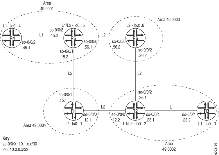
The network consists of Level 1 and Level 2 adjacencies. Level 1 adjacencies are within areas 49.0001 and 49.0002. Level 2 adjacencies occur between all directly connected Level 2 routers regardless of which area they are in. For example, R5 is in area 49.0001, R6 is in area 49.0003, R1 is in area 49.0004, and R2 is in area 49.0002. The network in Figure 1 should have the following adjacencies:
Level 2 adjacencies between all directly connected Level 2 routers (R1, R2, R5, and R6).
Level 1 adjacencies between routers in area 49.0001 (R4 and R5) and between routers in area 49.0002 (R2 and R3).
To verify that routers are adjacent and able to exchange IS-IS data, follow these steps:
Verifying Adjacent Routers
Purpose
Verify that routers are adjacent and able to exchange IS-IS data.
Action
To verify that routers are adjacent and able to exchange IS-IS data, enter the following CLI operational mode command:
user@host>
 show isis adjacency
The following sample output shows the adjacencies that formed for all routers shown in Displaying the Status of IS-IS Adjacencies .
Sample Output
command-name
user@R1> show isis adjacency
Interface             System         L State        Hold (secs) SNPA
so-0/0/0.0             R2             2 Up                   19
so-0/0/1.0             R5            2 Up                   18

user@R2> show isis adjacency
Interface             System         L State        Hold (secs) SNPA
so-0/0/0.0             R1             2 Up                   19
so-0/0/1.0             R3             1 Up                   26
so-0/0/2.0             R6             2 Up                   21

user@R3> show isis adjacency
Interface             System         L State        Hold (secs) SNPA
so-0/0/1.0             R2             1 Up                   24

user@R4> show isis adjacency
Interface             System         L State        Hold (secs) SNPA
so-0/0/2.0             R5             1 Up                   23

user@R5> show isis adjacency
Interface             System         L State        Hold (secs) SNPA
so-0/0/0.0             R6            2 Up                   22
so-0/0/1.0             R1            2 Up                   20
so-0/0/2.0             R4             1 Up                   20

user@R6> show isis adjacency
Interface             System         L State        Hold (secs) SNPA
so-0/0/0.0             R5             2 Up                   21
so-0/0/2.0             R2             2 Up                   20
Meaning
The sample output shows the adjacencies that formed in the network illustrated in Displaying the Status of IS-IS Adjacencies . The Level 1/Level 2 routers (R2 and R5) formed Level 1 adjacencies with Level 1 routers (R3 and R4), and Level 2 adjacencies with the Level 2 routers (R1 and R6). To view the status of the adjacency, examine the State column. In this example, all adjacencies in the network are up.
If the state is not Up for a particular neighbor,
you must first examine the IS-IS configuration for the particular
interface. Make sure that the NET address is correct and that the
loopback interface (lo0) is configured. Use the show isis interface or show isis interface detail command to display the
IS-IS parameters for all interfaces configured with IS-IS. With these
two commands, you can see which interfaces are configured for IS-IS,
whether they are configured for Level 1 or Level 2, the IS-IS metric,
and other IS-IS information.
See Also
Examine the Forwarding Table
Purpose
You can display the set of routes installed in the forwarding table to verify that the routing protocol process (rpd) has relayed the correct information into the forwarding table. This is especially important when there are network problems, such as connectivity. In this procedure, you verify that the routes displayed in Step 2 appear in the forwarding table for Router R5.
Action
To examine the forwarding table for a router, enter the following CLI command:
user@host>
show route forwarding-table destination destination-prefix
Sample Output
command-name
user@R5> show route forwarding-table destination
10.0.0.3
Routing table: inet
Internet:
Destination        Type RtRef Next hop           Type Index NhRef Netif
10.0.0.3/32        user     0 10.1.15.0          ucst   285     7  so-0/0/1.0
user@R5> show route forwarding-table destination 10.0.0.3
Routing table: inet
Internet:
Destination        Type RtRef Next hop           Type Index NhRef Netif
10.0.0.3/32        user     0 10.1.56.0          ucst   281     9  so-0/0/0.0
Meaning
The sample output shows the selected next hop between Routers R5 and R3 sent from the inet routing table and installed into the forwarding table. The first instance shows the route through Router R1, and the second instance shows the route through Router R6. In both instances, the preferred route displayed in Step 2 is installed in the forwarding table.
In general, the sample output includes the destination address and destination type, the next-hop address and next-hop type, the number of references to the next hop, an index number into an internal next-hop database, and the interface used to reach the next hop.