ON THIS PAGE
Example: Configuring Topology Independent Loop-Free Alternate with Segment Routing for IS-IS
This example shows topology-independent loop-free alternate (TI-LFA) with segment routing for the IS-IS protocol to provide MPLS fast reroute (FRR) backup paths corresponding to the post-convergence path for a given failure by using deeper label stacks to construct backup paths. TI-LFA provides protection against link failure, node failure, and fate-sharing failures. In link failure mode, the destination is protected if the link fails. In node protection mode, the destination is protected if the neighbor connected to the primary link fails. To determine the node-protecting post-convergence path, the cost of all the links leaving the neighbor is assumed to increase by a configurable amount. With fate-sharing protection, a list of fate-sharing groups are configured on each PLR with the links in each fate-sharing group identified by their respective IP addresses.
Our content testing team has validated and updated this example.
Requirements
This example uses the following hardware and software components:
Nine MX Series routers
Junos OS Release 17.4 or later running on all devices
-
Updated and revalidated using vMX on Junos OS Release 21.1R1.
-
Before you configure TI-LFA routes using SPRING for IS-IS, be sure you configure SPRING or segment routing.
Are you interested in getting hands-on experience on this feature?
Visit Juniper vLabs to reserve your pre-configured vLab Sandbox: Segment Routing - Basic and try it out for free!
Overview
Junos OS allows you to enable TI-LFA for IS-IS by configuring the
use-post-convergence-lfa statement at the [edit
protocols isis backup-spf-options] hierarchy level. You can enable the
creation of post-convergence backup paths for a given interface by configuring the
post-convergence-lfa statement at the [edit protocols isis interface
interface-name level level] hierarchy level.
TI-LFA provides protection against link failure, node failure, and failures of
fate-sharing groups. You can enable link-protection mode using the
post-convergence-lfa statement. You can enable
node-protection mode, or
fate-sharing-protection mode, or both modes, for a given
interface at the [edit protocols isis interface interface-name level level
post-convergence-lfa] hierarchy level. To ensure that the fate-sharing
protection is enabled for a given fate-sharing group, you need to configure the
use-for-post-convergence-lfa statement at the [edit
routing-options fate-sharing group group-name] hierarchy level.
TI-LFA supports protection of routes for both IPv4 and IPv6 prefixes. This example demonstrates protection of routes for IPv4 prefixes.
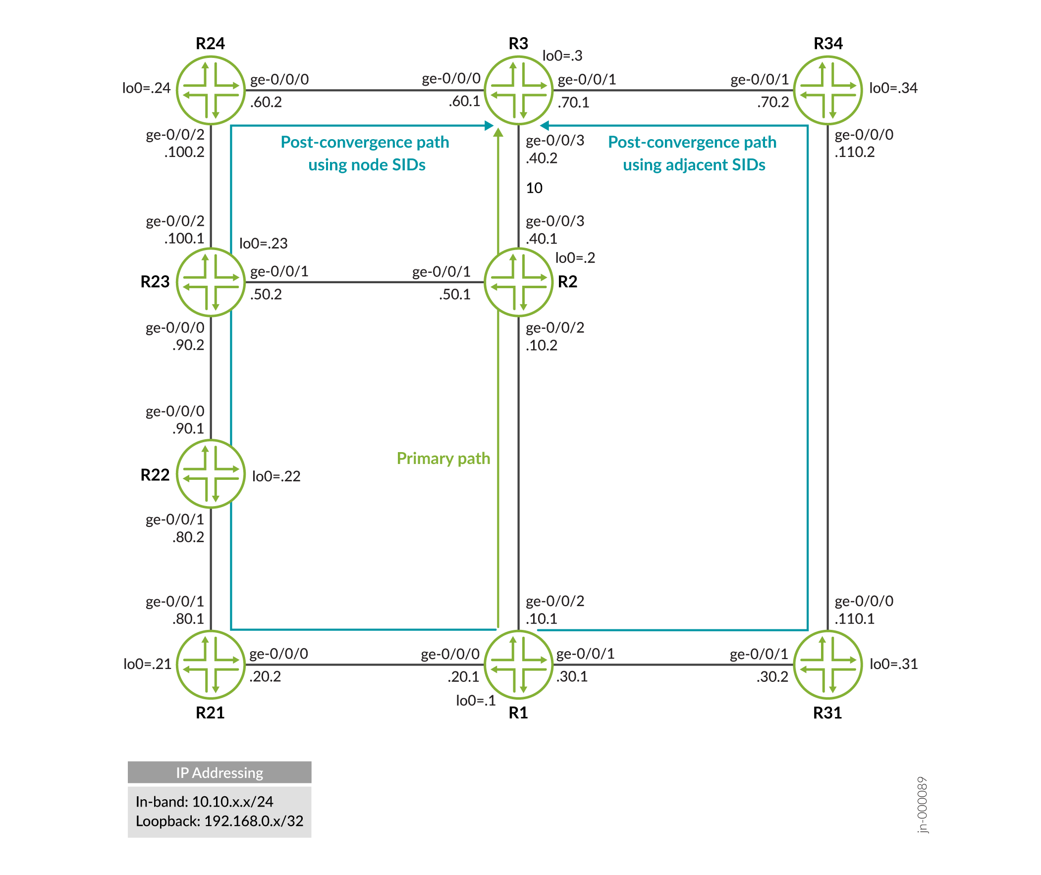
Topology
Configuration
CLI Quick Configuration
To quickly configure link-protection in this example, copy the following commands, paste them into a text file, remove any line breaks, change any details necessary to match your network configuration, copy and paste the commands into the CLI at the [edit] hierarchy level, and then enter commit from configuration mode.
R1
set interfaces ge-0/0/0 unit 0 description r1-to-r21
set interfaces ge-0/0/0 unit 0 family inet address 10.10.20.1/24
set interfaces ge-0/0/0 unit 0 family iso
set interfaces ge-0/0/0 unit 0 family mpls
set interfaces ge-0/0/1 unit 0 description r1-to-r31
set interfaces ge-0/0/1 unit 0 family inet address 10.10.30.1/24
set interfaces ge-0/0/1 unit 0 family iso
set interfaces ge-0/0/1 unit 0 family mpls
set interfaces ge-0/0/2 unit 0 description r1-to-r2
set interfaces ge-0/0/2 unit 0 family inet address 10.10.10.1/24
set interfaces ge-0/0/2 unit 0 family iso
set interfaces ge-0/0/2 unit 0 family mpls
set interfaces lo0 unit 0 family inet address 198.168.0.1/32
set interfaces lo0 unit 0 family iso address 49.0000.2222.0001.00
set interfaces lo0 unit 0 family mpls
set protocols isis interface ge-0/0/0.0 level 2 disable
set protocols isis interface ge-0/0/0.0 point-to-point
set protocols isis interface ge-0/0/1.0 level 2 disable
set protocols isis interface ge-0/0/1.0 point-to-point
set protocols isis interface ge-0/0/2.0 level 2 disable
set protocols isis interface ge-0/0/2.0 level 1 post-convergence-lfa
set protocols isis interface ge-0/0/2.0 point-to-point
set protocols isis interface fxp0.0 disable
set protocols isis interface lo0.0 passive
set protocols isis source-packet-routing node-segment ipv4-index 1001
set protocols isis backup-spf-options use-post-convergence-lfa maximum-labels 8
set protocols mpls interface ge-0/0/0.0
set protocols mpls interface ge-0/0/1.0
set protocols mpls interface ge-0/0/2.0
set policy-options policy-statement pplb then load-balance per-packet
set routing-options forwarding-table export pplb
set routing-options router-id 198.168.0.1
R2
set interfaces ge-0/0/1 unit 0 description r2-to-r23
set interfaces ge-0/0/1 unit 0 family inet address 10.10.50.1/24
set interfaces ge-0/0/1 unit 0 family iso
set interfaces ge-0/0/1 unit 0 family mpls
set interfaces ge-0/0/2 unit 0 description r2-to-r1
set interfaces ge-0/0/2 unit 0 family inet address 10.10.10.2/24
set interfaces ge-0/0/2 unit 0 family iso
set interfaces ge-0/0/2 unit 0 family mpls
set interfaces ge-0/0/3 unit 0 description r2-to-r3
set interfaces ge-0/0/3 unit 0 family inet address 10.10.40.1/24
set interfaces ge-0/0/3 unit 0 family iso
set interfaces ge-0/0/3 unit 0 family mpls
set interfaces lo0 unit 0 family inet address 192.168.0.2/32
set interfaces lo0 unit 0 family iso address 49.0000.2222.0002.00
set interfaces lo0 unit 0 family mpls
set protocols isis interface ge-0/0/1.0 level 2 disable
set protocols isis interface ge-0/0/1.0 point-to-point
set protocols isis interface ge-0/0/2.0 level 2 disable
set protocols isis interface ge-0/0/2.0 point-to-point
set protocols isis interface ge-0/0/3.0 level 2 disable
set protocols isis interface ge-0/0/3.0 point-to-point
set protocols isis interface fxp0.0 disable
set protocols isis interface lo0.0 passive
set protocols isis source-packet-routing node-segment ipv4-index 1002
set protocols mpls interface ge-0/0/1.0
set protocols mpls interface ge-0/0/2.0
set protocols mpls interface ge-0/0/3.0
set routing-options router-id 192.168.0.2
R3
set interfaces ge-0/0/0 unit 0 description r3-to-r24
set interfaces ge-0/0/0 unit 0 family inet address 10.10.60.1/24
set interfaces ge-0/0/0 unit 0 family iso
set interfaces ge-0/0/0 unit 0 family mpls
set interfaces ge-0/0/1 unit 0 description r3-to-r34
set interfaces ge-0/0/1 unit 0 family inet address 10.10.70.1/24
set interfaces ge-0/0/1 unit 0 family iso
set interfaces ge-0/0/1 unit 0 family mpls
set interfaces ge-0/0/3 unit 0 description r3-to-r2
set interfaces ge-0/0/3 unit 0 family inet address 10.10.40.2/24
set interfaces ge-0/0/3 unit 0 family iso
set interfaces ge-0/0/3 unit 0 family mpls
set interfaces lo0 unit 0 family inet address 192.168.0.3/32
set interfaces lo0 unit 0 family iso address 49.0000.2222.0003.00
set interfaces lo0 unit 0 family mpls
set protocols isis interface ge-0/0/0.0 level 2 disable
set protocols isis interface ge-0/0/0.0 point-to-point
set protocols isis interface ge-0/0/1.0 level 2 disable
set protocols isis interface ge-0/0/1.0 point-to-point
set protocols isis interface ge-0/0/3.0 level 2 disable
set protocols isis interface ge-0/0/3.0 point-to-point
set protocols isis interface fxp0.0 disable
set protocols isis interface lo0.0 passive
set protocols isis source-packet-routing node-segment ipv4-index 1003
set protocols mpls interface ge-0/0/0.0
set protocols mpls interface ge-0/0/1.0
set protocols mpls interface ge-0/0/3.0
set routing-options router-id 192.168.0.3
R21
set interfaces ge-0/0/0 unit 0 description r21-to-r1
set interfaces ge-0/0/0 unit 0 family inet address 10.10.20.2/24
set interfaces ge-0/0/0 unit 0 family iso
set interfaces ge-0/0/0 unit 0 family mpls
set interfaces ge-0/0/1 unit 0 description r21-to-r22
set interfaces ge-0/0/1 unit 0 family inet address 10.10.80.1/24
set interfaces ge-0/0/1 unit 0 family iso
set interfaces ge-0/0/1 unit 0 family mpls
set interfaces lo0 unit 0 family inet address 192.168.0.21/32
set interfaces lo0 unit 0 family iso address 49.0000.2222.0021.00
set interfaces lo0 unit 0 family mpls
set protocols isis interface ge-0/0/0.0 level 2 disable
set protocols isis interface ge-0/0/0.0 point-to-point
set protocols isis interface ge-0/0/1.0 level 2 disable
set protocols isis interface ge-0/0/1.0 point-to-point
set protocols isis interface fxp0.0 disable
set protocols isis interface lo0.0 passive
set protocols isis source-packet-routing node-segment ipv4-index 1021
set protocols mpls interface ge-0/0/0.0
set protocols mpls interface ge-0/0/1.0
set routing-options router-id 192.168.0.21
R22
set interfaces ge-0/0/0 unit 0 description r22-to-r23
set interfaces ge-0/0/0 unit 0 family inet address 10.10.90.1/24
set interfaces ge-0/0/0 unit 0 family iso
set interfaces ge-0/0/0 unit 0 family mpls
set interfaces ge-0/0/1 unit 0 description r22-to-r21
set interfaces ge-0/0/1 unit 0 family inet address 10.10.80.2/24
set interfaces ge-0/0/1 unit 0 family iso
set interfaces ge-0/0/1 unit 0 family mpls
set interfaces lo0 unit 0 family inet address 192.168.0.22/32
set interfaces lo0 unit 0 family iso address 49.0000.2222.0022.00
set interfaces lo0 unit 0 family mpls
set protocols isis interface ge-0/0/0.0 level 2 disable
set protocols isis interface ge-0/0/0.0 point-to-point
set protocols isis interface ge-0/0/1.0 level 2 disable
set protocols isis interface ge-0/0/1.0 point-to-point
set protocols isis interface fxp0.0 disable
set protocols isis interface lo0.0 passive
set protocols isis source-packet-routing node-segment ipv4-index 1022
set protocols mpls interface ge-0/0/0.0
set protocols mpls interface ge-0/0/1.0
set routing-options router-id 192.168.0.22
R23
set interfaces ge-0/0/0 unit 0 description r23-to-r22
set interfaces ge-0/0/0 unit 0 family inet address 10.10.90.2/24
set interfaces ge-0/0/0 unit 0 family iso
set interfaces ge-0/0/0 unit 0 family mpls
set interfaces ge-0/0/1 unit 0 description r23-to-r2
set interfaces ge-0/0/1 unit 0 family inet address 10.10.50.2/24
set interfaces ge-0/0/1 unit 0 family iso
set interfaces ge-0/0/1 unit 0 family mpls
set interfaces ge-0/0/2 unit 0 description r23-to-r24
set interfaces ge-0/0/2 unit 0 family inet address 10.10.100.1/24
set interfaces ge-0/0/2 unit 0 family iso
set interfaces ge-0/0/2 unit 0 family mpls
set interfaces lo0 unit 0 family inet address 192.168.0.23/32
set interfaces lo0 unit 0 family iso address 49.0000.2222.0023.00
set interfaces lo0 unit 0 family mpls
set protocols isis interface ge-0/0/0.0 level 2 disable
set protocols isis interface ge-0/0/0.0 point-to-point
set protocols isis interface ge-0/0/1.0 level 2 disable
set protocols isis interface ge-0/0/1.0 point-to-point
set protocols isis interface ge-0/0/2.0 level 2 disable
set protocols isis interface ge-0/0/2.0 point-to-point
set protocols isis interface fxp0.0 disable
set protocols isis interface lo0.0 passive
set protocols isis source-packet-routing node-segment ipv4-index 1023
set protocols mpls interface ge-0/0/0.0
set protocols mpls interface ge-0/0/1.0
set protocols mpls interface ge-0/0/2.0
set routing-options router-id 192.168.0.23
R24
set interfaces ge-0/0/0 unit 0 description r24-to-r3
set interfaces ge-0/0/0 unit 0 family inet address 10.10.60.2/24
set interfaces ge-0/0/0 unit 0 family iso
set interfaces ge-0/0/0 unit 0 family mpls
set interfaces ge-0/0/2 unit 0 description r24-to-r23
set interfaces ge-0/0/2 unit 0 family inet address 10.10.100.2/24
set interfaces ge-0/0/2 unit 0 family iso
set interfaces ge-0/0/2 unit 0 family mpls
set interfaces lo0 unit 0 family inet address 192.168.0.24/32
set interfaces lo0 unit 0 family iso address 49.0000.2222.0024.00
set interfaces lo0 unit 0 family mpls
set protocols isis interface ge-0/0/0.0 level 2 disable
set protocols isis interface ge-0/0/0.0 point-to-point
set protocols isis interface ge-0/0/2.0 level 2 disable
set protocols isis interface ge-0/0/2.0 point-to-point
set protocols isis interface fxp0.0 disable
set protocols isis interface lo0.0 passive
set protocols isis source-packet-routing node-segment ipv4-index 1024
set protocols mpls interface ge-0/0/0.0
set protocols mpls interface ge-0/0/2.0
set routing-options router-id 192.168.0.24
R31
set interfaces ge-0/0/0 unit 0 description r31-to-r34
set interfaces ge-0/0/0 unit 0 family inet address 10.10.110.1/24
set interfaces ge-0/0/0 unit 0 family iso
set interfaces ge-0/0/0 unit 0 family mpls
set interfaces ge-0/0/1 unit 0 description r31-to-r1
set interfaces ge-0/0/1 unit 0 family inet address 10.10.30.2/24
set interfaces ge-0/0/1 unit 0 family iso
set interfaces ge-0/0/1 unit 0 family mpls
set interfaces lo0 unit 0 family inet address 198.162.0.31/32
set interfaces lo0 unit 0 family iso address 49.0000.2222.0031.00
set interfaces lo0 unit 0 family mpls
set protocols isis interface ge-0/0/0.0 level 1 metric 500
set protocols isis interface ge-0/0/0.0 level 2 disable
set protocols isis interface ge-0/0/0.0 point-to-point
set protocols isis interface ge-0/0/1.0 level 1 metric 10
set protocols isis interface ge-0/0/1.0 level 2 disable
set protocols isis interface ge-0/0/1.0 point-to-point
set protocols isis interface fxp0.0 disable
set protocols isis interface lo0.0 passive
set protocols isis source-packet-routing node-segment ipv4-index 1031
set protocols mpls interface ge-0/0/1.0
set protocols mpls interface ge-0/0/0.0
set routing-options router-id 198.162.0.31
R34
set interfaces ge-0/0/0 unit 0 description r34-to-r31
set interfaces ge-0/0/0 unit 0 family inet address 10.10.110.2/24
set interfaces ge-0/0/0 unit 0 family iso
set interfaces ge-0/0/0 unit 0 family mpls
set interfaces ge-0/0/1 unit 0 description r34-to-r3
set interfaces ge-0/0/1 unit 0 family inet address 10.10.70.2/24
set interfaces ge-0/0/1 unit 0 family iso
set interfaces ge-0/0/1 unit 0 family mpls
set interfaces lo0 unit 0 family inet address 192.168.0.34/32
set interfaces lo0 unit 0 family iso address 49.0000.2222.0034.00
set interfaces lo0 unit 0 family mpls
set protocols isis interface ge-0/0/0.0 level 1 metric 500
set protocols isis interface ge-0/0/0.0 level 2 disable
set protocols isis interface ge-0/0/0.0 point-to-point
set protocols isis interface ge-0/0/1.0 level 1 metric 10
set protocols isis interface ge-0/0/1.0 level 2 disable
set protocols isis interface ge-0/0/1.0 point-to-point
set protocols isis interface fxp0.0 disable
set protocols isis interface lo0.0 passive
set protocols isis source-packet-routing node-segment ipv4-index 1034
set protocols mpls interface ge-0/0/0.0
set protocols mpls interface ge-0/0/1.0
set routing-options router-id 192.168.0.34
Configuring R1
Step-by-Step Procedure
The following example requires that you navigate various levels in the configuration hierarchy. For information about navigating the CLI, see Using the CLI Editor in Configuration Mode in the Junos OS CLI User Guide.
To configure Device R1:
-
Configure the interfaces.
[edit interfaces]
user@R1# set ge-0/0/0 unit 0 description r1-to-r21
user@R1# set ge-0/0/0 unit 0 family inet address 10.10.20.1/24
user@R1# set ge-0/0/0 unit 0 family iso
user@R1# set ge-0/0/0 unit 0 family mpls

user@R1# set ge-0/0/1 unit 0 description r1-to-r31
user@R1# set ge-0/0/1 unit 0 family inet address 10.10.30.1/24
user@R1# set ge-0/0/1 unit 0 family iso
user@R1# set ge-0/0/1 unit 0 family mpls

user@R1# set ge-0/0/2 unit 0 description r1-to-r2
user@R1# set ge-0/0/2 unit 0 family inet address 10.10.10.1/24
user@R1# set ge-0/0/2 unit 0 family iso
user@R1# set ge-0/0/2 unit 0 family mpls

user@R1# set lo0 unit 0 family inet address 198.168.0.1/32
user@R1# set lo0 unit 0 family iso address 49.0000.2222.0001.00
user@R1# set lo0 unit 0 family mpls
-
Configure the router ID.
[edit routing-options]
user@R1# set router-id 198.168.0.1
-
Configure MPLS.
[edit protocols]
user@R1# set mpls interface ge-0/0/0.0
user@R1# set mpls interface ge-0/0/1.0
user@R1# set mpls interface ge-0/0/2.0
-
Configure IS-IS.
[edit protocols]
user@R1# set isis interface ge-0/0/0.0 level 2 disable
user@R1# set isis interface ge-0/0/0.0 point-to-point

user@R1# set isis interface ge-0/0/1.0 level 2 disable
user@R1# set isis interface ge-0/0/1.0 point-to-point

user@R1# set isis interface ge-0/0/2.0 level 2 disable
user@R1# set isis interface ge-0/0/2.0 point-to-point

user@R1# set isis interface lo0.0 passive

user@R1# set isis interface fxp0.0 disable
-
Configure to install backup route along the link-protecting post-convergence path on interface ge-0/0/2.
[edit protocols]
user@R1# set isis interface ge-0/0/2.0 level 1 post-convergence-lfa
-
Configure the maximum number of labels for segment routing routed paths for protection of backup shortest-path-first attributes.
[edit protocols]
user@R1# set isis backup-spf-options use-post-convergence-lfa maximum-labels 8
-
Configure IPv4 index and index range for node segments in segment routing for the IS-IS protocol.
[edit protocols]
user@R1# set isis source-packet-routing node-segment ipv4-index 1001
-
(Optional) Enable node-protection on interface ge-0/0/2.
[edit protocols]
user@R1# set isis interface ge-0/0/2 level 2 post-convergence-lfa node-protection cost 2000
-
(Optional) Configure the fate-sharing group cost.
[edit routing-options]
user@R1# set fate-sharing group fs-group-1 cost 3000
-
(Optional) Configure the fate-sharing group to indicate that link from Device R1 to Device R2 and the link from Device R21 to Device R22 share fate and allow it to be used for post-convergence-lfa.
[edit routing-options]
user@R1# set fate-sharing group fs-group-1 from 10.10.10.1 to 10.10.10.2
user@R1# set fate-sharing group fs-group-1 from 10.10.80.1 to 10.10.80.2
user@R1# set fate-sharing group fs-group-1 use-for-post-convergence-lfa
-
(Optional) Enable fate-sharing protection for ge-0/0/2 on Device R1.
[edit protocols]
user@R1# set isis interface ge-0/0/2 level 2 post-convergence-lfa fate-sharing-protection
-
Configure a per packet load-balance policy for TI-LFA to work and ensure faster convergence.
[edit]
user@R1# set policy-options policy-statement pplb then load-balance per-packet
-
Apply the policy to export the routes into the forwarding table.
[edit]
user@R1# set routing-options forwarding-table export pplb
Results
From configuration mode, confirm your configuration by entering the show
interfaces, show protocols and show
routing-options commands. If the output does not display the
intended configuration, repeat the instructions in this example to correct the
configuration.
user@R1# show interfaces
ge-0/0/0 {
    unit 0 {
        description r1-to-r21;
        family inet {
            address 10.10.20.1/24;
        }
        family iso;
        family mpls;
    }
}
ge-0/0/1 {
    unit 0 {
        description r1-to-r31;
        family inet {
            address 10.10.30.1/24;
        }
        family iso;
        family mpls;
    }
}
ge-0/0/2 {
    unit 0 {
        description r1-to-r2;
        family inet {
            address 10.10.10.1/24;
        }
        family iso;
        family mpls;
    }
}
lo0 {
    unit 0 {
        family inet {
            address 198.168.0.1/32;
        }
        family iso {
            address 49.0000.2222.0001.00;
        }
        family mpls;
    }
}user@R1# show routing-options
router-id 198.168.0.1;
forwarding-table {
export pplb;
}user@R1# show policy-options
policy-statement pplb {
then {
load-balance per-packet;
}
}user@R1# show protocols
isis {
interface ge-0/0/0.0 {
level 2 disable;
point-to-point;
}
interface ge-0/0/1.0 {
level 2 disable;
point-to-point;
}
interface ge-0/0/2.0 {
level 2 disable;
level 1 {
post-convergence-lfa;
}
point-to-point;
}
interface fxp0.0 {
disable;
}
interface lo0.0 {
passive;
}
source-packet-routing {
node-segment ipv4-index 1001;
}
backup-spf-options {
use-post-convergence-lfa maximum-labels 8;
}
}
mpls {
interface ge-0/0/0.0;
interface ge-0/0/1.0;
interface ge-0/0/2.0;
}If you are done configuring the device, enter commit from
configuration mode.
Verification
Confirm that the configuration is working properly.
- Verify the TI-LFA routes using node SIDs
- Verify adjacency SIDs
- Verify the TI-LFA routes using adjacency SIDs
Verify the TI-LFA routes using node SIDs
Purpose
Verify the link-protecting backup path for primary next hops on interface ge-0/0/2 for Device R1 and verify if the backup path to reach 192.168.0.3/32 has been created and has the correct label stack.
Action
From operational mode, run the show route 192.168.0.3 command to display the
routing table information.
user@R1> show route 192.168.0.3

inet.0: 38 destinations, 38 routes (38 active, 0 holddown, 0 hidden)
+ = Active Route, - = Last Active, * = Both

192.168.0.3/32     *[IS-IS/15] 09:52:56, metric 20
                    >  to 10.10.10.2 via ge-0/0/2.0

inet.3: 8 destinations, 8 routes (8 active, 0 holddown, 0 hidden)
+ = Active Route, - = Last Active, * = Both

192.168.0.3/32     *[L-ISIS/14] 05:45:40, metric 20
                    >  to 10.10.10.2 via ge-0/0/2.0, Push 801003
                       to 10.10.20.2 via ge-0/0/0.0, Push 801003, Push 801024(top)
Meaning
The primary path to reach 198.168.0.3/32 (corresponding to Device R3) is through the interface ge-0/0/2 with a label of 801003, corresponding to the node-SID of Device R3. If the interface ge-0/0/2 fails, the backup path using the interface ge-0/0/0 using the label stack [801024, 801003] becomes active. The link-protecting post-convergence path is R1-R21-R22-R23-R24-R3. The top label on the label stack is 801024 and corresponds to the node SID to reach R24. The 801003 label corresponds to the node SID on R23 to reach R3 on the shortest path R23-R2-R3.
Verify adjacency SIDs
Verify adjacency SIDs of devices that have IS-IS adjacencies with Device R1.
The SID values can vary in your configuration setup.
Action
From operational mode, run the show isis adjacency
detail command to display the adjacency information on
Device R1.
user@R1> show isis adjacency detail
R21
  Interface: ge-0/0/0.0, Level: 1, State: Up, Expires in 19 secs
  Priority: 0, Up/Down transitions: 3, Last transition: 07:06:07 ago
  Circuit type: 1, Speaks: IP, IPv6
  Topologies: Unicast
  Restart capable: Yes, Adjacency advertisement: Advertise
  IP addresses: 10.10.20.2
  Level 1 IPv4 Adj-SID: 299840

R31
  Interface: ge-0/0/1.0, Level: 1, State: Up, Expires in 22 secs
  Priority: 0, Up/Down transitions: 3, Last transition: 07:06:07 ago
  Circuit type: 1, Speaks: IP, IPv6
  Topologies: Unicast
  Restart capable: Yes, Adjacency advertisement: Advertise
  IP addresses: 10.10.30.2
  Level 1 IPv4 Adj-SID: 299808

R2
  Interface: ge-0/0/2.0, Level: 1, State: Up, Expires in 24 secs
  Priority: 0, Up/Down transitions: 3, Last transition: 07:06:07 ago
  Circuit type: 1, Speaks: IP, IPv6
  Topologies: Unicast
  Restart capable: Yes, Adjacency advertisement: Advertise
  IP addresses: 10.10.10.2
  Level 1 IPv4 Adj-SID: 299776
Meaning
Adjacency SIDs are assigned to each adjacency of Device R1 in the segment routing domain:
- Device R21 - 299840
- Device R31 - 299808
- Device R2 - 299776
The adjacency SIDs have local significance and can be used to steer traffic along specific outgoing interfaces. When you do not configure adjacency SIDs, they are dynamically assigned with a value outside of the default (or configured) SRGB range.
Verify the TI-LFA routes using adjacency SIDs
Purpose
Increase the cost of the post-convergence path from R1 to R3 and verify the TI-LFA routes using adjacency SIDs to avoid the primary path to reach the destination, Device R3.
Action
From the configuration mode, increase the cost of the interface connecting Device R22 and R23, ge-0/0/0.
[edit protocols]
user@R22# set protocols isis interface ge-0/0/0.0 level 1 metric 1000
user@R22# commit
From operational mode, again run the show route 192.168.0.3 command.
user@R1> show route 192.168.0.3

inet.0: 38 destinations, 38 routes (38 active, 0 holddown, 0 hidden)
+ = Active Route, - = Last Active, * = Both

192.168.0.3/32     *[IS-IS/15] 10:44:56, metric 20
                    >  to 10.10.10.2 via ge-0/0/2.0

inet.3: 8 destinations, 8 routes (8 active, 0 holddown, 0 hidden)
+ = Active Route, - = Last Active, * = Both

192.168.0.3/32     *[L-ISIS/14] 00:00:31, metric 20
                    >  to 10.10.10.2 via ge-0/0/2.0, Push 801003
                       to 10.10.30.2 via ge-0/0/1.0, Push 801003, Push 299808(top)
Meaning
The TI-LFA backup paths are now using the adjacency SID (in this case, 299808) instead of the node SID (801003) to reach Device R3. This is because node SIDs always use the shortest path between two nodes, and when the R22-R23 link cost went up, the shortest path to R1 overlaps with the primary path. Because TI-LFA cannot take a primary path to reach the destination, adjacency SIDs are used to take R31-R34 as the new post-convergence path to reach Device R3.