ON THIS PAGE
Configuring 3G Wireless Modems for WAN Connections
The topics below discuss the overview and configuration of 3G Wireless Modem, dialer interface, and 3G Wireless Modem physical interface.
3G Wireless Modem Overview
3G refers to the third generation of mobile phone standards and technology based on the International Telecommunication Union (ITU) International Mobile Telecommunications-2000 (IMT-2000) global standard. 3G networks are wide area cellular telephone networks that have evolved to include high-data rate services of up to 3 Mbps. This increased bandwidth makes 3G networks a viable option as primary or backup wide area network (WAN) links for a branch office.
Juniper Networks security devices support 3G wireless interfaces (USB-based 3G modems). When used in a branch office, these devices can provide dial-out services to PC users and forward IP traffic through a service provider’s cellular network.
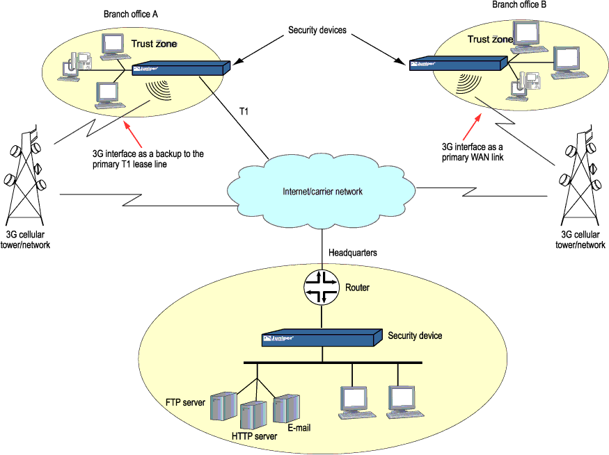
Figure 1 illustrates a basic setup for 3G wireless connectivity for two branch offices. Branch Office A has a T1 leased line as the primary wide area network (WAN) link and a 3G wireless modem connection as the failover link. Branch Office B uses the 3G wireless modem connection as the primary WAN link.
3G Wireless Modem Configuration Overview
Before you begin:
To configure and activate the 3G wireless modem card:
Configure a dialer interface. See Example: Configuring the Dialer Interface.
Configure the 3G wireless modem interface. See Example: Configuring the 3G Wireless Modem Interface.
Configure security zones and policies, as needed, to allow traffic through the WAN link. See Example: Creating Security Zones.
To use the 3G USB modems on the SRX210 device:
Upgrade the BIOS software packaged inside the Junos OS image. For detailed information about BIOS upgrade procedures, see the Software Installation and Upgrade Guide.
Note:You need the BIOS version of 2.1 or higher to use the 3G USB modems on the SRX210 device.
Configure the WAN port using the CLI command
set
chassis routing-engine usb-wwan port 1
to enable the USB port to use the U319 USB modem.Plug the 3G USB modem in to the appropriate USB slot (USB port 1) on the device.
Note:You can use the USB modem with a standard USB extension cable of 1.8288 meters (6 ft) or longer.
Reboot the device to start using the 3G USB modem.
Understanding the Dialer Interface
The dialer interface, dln, is a logical interface for
configuring properties for modem connections. You can configure multiple dialer
interfaces on an SRX Series Firewall. A dialer interface and a dialer pool (which
includes the physical interface) are bound together in a dialer profile.
The dialer interface for 3G wireless modems is no longer supported on SRX300, SRX320, SRX340, SRX345, SRX380, and SRX550HM devices.
This topic contains the following sections:
- Dialer Interface Configuration Rules
- Dialer Interface Authentication Support for GSM HSDPA 3G Wireless Modems
- Dialer Interface Functions
- Dialer Interface Operating Parameters
Dialer Interface Configuration Rules
The following rules apply when you configure dialer interfaces for 3G wireless modem connections:
The dialer interface must be configured to use the default Point-to-Point Protocol (PPP) encapsulation. You cannot configure Cisco High-Level Data Link Control (HDLC) or Multilink PPP (MLPPP) encapsulation on dialer interfaces.
You cannot configure the dialer interface as a constituent link in a multilink bundle.
You cannot configure any dial-in options for the dialer interface.
You configure the following for a dialer interface:
A dialer pool to which the physical interface belongs.
Source IP address for the dialer interface.
Dial string (optional) is the destination number to be dialed.
Authentication, for GSM HSDPA 3G wireless modem cards.
Watch list, if the dialer interface is a backup WAN link.
With GSM HSDPA 3G wireless modem cards, you might need to configure PAP or CHAP for authentication with the service provider network. The service provider must supply the username and password, which you configure in an access profile. You then specify the access profile in a dialer interface.
Next you set the dialer interface as a backup WAN link to a primary interface. Then you create a dialer watch to enable the device to monitor the route to a head office router and set a dialer pool. Finally, you create a dialer filter firewall rule for traffic from the branch office to the main office router and associate the dialer filter with a dialer interface.
Dialer Interface Authentication Support for GSM HSDPA 3G Wireless Modems
For GSM HSDPA 3G wireless modems, you configure a dialer interface to support authentication through Challenge Handshake Authentication Protocol (CHAP) or Password Authentication Protocol (PAP).
CHAP is a server-driven, three-step authentication method that depends on a shared secret password that resides on both the server and the client. When you enable CHAP on a dialer interface, the device can authenticate its peer and be authenticated by its peer.
PAP allows a simple method for a peer to establish its identity using a two-way handshake during initial link establishment. After the link is established, an identification and password pair is repeatedly sent by the peer to the authenticator until authentication is acknowledged or the connection is terminated.
Dialer Interface Functions
The dialer interface can perform backup, dialer filter, and dialer watch functions, but these operations are mutually exclusive. You can configure a single dialer interface to operate in only one of the following ways:
As a backup interface for a single primary WAN connection. The dialer interfaces are activated only when the primary interface fails. The 3G wireless modem backup connectivity is supported on all interfaces except
lsq-0/0/0.As a dialer filter. The Dialer filter enables the 3G wireless modem connection to be activated only when specific network traffic is sent on the backup WAN link. You configure a firewall rule with the dialer filter option, and then apply the dialer filter to the dialer interface.
As a dialer watch interface. With dialer watch, the SRX Series Firewall monitors the status of a specified route and if the route disappears, the dialer interface initiates the 3G wireless modem connection as a backup connection. To configure dialer watch, you first add the routes to be monitored to a watch list in a dialer interface; specify a dialer pool for this configuration. Then configure the 3G wireless modem interface to use the dialer pool.
Dialer Interface Operating Parameters
You can also specify optional operating parameters for the dialer interface:
Activation delay—Number of seconds after the primary interface is down before the backup interface is activated. The default value is 0 seconds, and the maximum value is 60 seconds. Use this option only if dialer watch is configured.
Deactivation delay—Number of seconds after the primary interface is up before the backup interface is deactivated. The default value is 0 seconds, and the maximum value is 60 seconds. Use this option only if dialer watch is configured.
Idle timeout—Number of seconds the connection remains idle before disconnecting. The default value is 120 seconds, and the range is from 0 to 4,294,967,295 seconds.
Initial route check—Number of seconds before the primary interface is checked to see if it is up. The default value is 120 seconds, and the range is from 1 to 300 seconds.
Example: Configuring the Dialer Interface
This example shows how to configure the dialer interface for 3G wireless modem connections.
The dialer interface for 3G wireless modems is no longer supported on SRX300, SRX320, SRX340, SRX345, SRX380, and SRX550HM devices.
Requirements
Before you begin, install your SRX Series Firewall and establish basic connectivity for your device. See 3G Wireless Modem Configuration Overview.
Overview
In this example, you first configure the dialer interface as dl0, specify the PPP encapsulation dialer pool as 1, specify the dial string as 14691, and negotiate the address option for the interface IP address.
Configuration
- Configuring a Dialer Interface
- Configuring PAP on the Dialer Interface
- Configuring CHAP on the Dialer Interface
- Configuring the Dialer Interface as a Backup WAN Connection
- Configuring Dialer Watch for the 3G Wireless Modem Interface
- Configuring a Dialer Filter for the 3G Wireless Modem Interface
Configuring a Dialer Interface
CLI Quick Configuration
To quickly configure this example, copy the
following command, paste it into a text file, remove any line breaks,
change any details necessary to match your network configuration,
copy and paste the command into the CLI at the [edit] hierarchy
level, and then enter commit from configuration mode.
set interfaces dl0 description 3g-wireless encapsulation ppp unit 0 dialer-options pool 1 dial-string 14691
set interfaces dl0 unit 0 family inet negotiate-address
Step-by-Step Procedure
Set the interface and specify the PPP encapsulation, dialer pool, and dial string.
[edit]
user@host# set interfaces dl0 description 3g-wireless encapsulation ppp unit 0 dialer-options pool 1 dial-string 14691
Set the negotiate address option for the interface IP address.
[edit]
user@host# set interfaces dl0 unit 0 family inet negotiate-address
Results
From configuration mode, confirm your configuration
by entering the show interfaces dl0 command. If the output
does not display the intended configuration, repeat the configuration
instructions in this example to correct it.
[edit]
    user@host# show interfaces dl0
description 3g-wireless;
encapsulation ppp;
    unit 0 {
family inet {
negotiate-address;
     }
dialer-options {
pool 1;
    dial-string 14691;
     }
}
If you are done configuring the device, enter commit from configuration mode.
Configuring PAP on the Dialer Interface
CLI Quick Configuration
To quickly configure this example, copy the
following command, paste it into a text file, remove any line breaks,
change any details necessary to match your network configuration,
copy and paste the command into the CLI at the [edit] hierarchy
level, and then enter commit from configuration mode.
set access profile pap-1 client clientX pap-password 7a^6b%5c
set interfaces dl0 unit 0 ppp-options pap access-profile pap-1
Step-by-Step Procedure
Configure a PAP access profile.
[edit]
user@host# set access profile pap-1 client clientX pap-password 7a^6b%5c
Associate the PAP access profile with a dialer interface.
[edit]
user@host# set interfaces dl0 unit 0 ppp-options pap access-profile pap-1
Results
From configuration mode, confirm your configuration
by entering the show interfaces dl0 and show access
profile pap-1 commands. If the output does not display the intended
configuration, repeat the configuration instructions in this example
to correct it.
[edit]
    user@host# show interfaces dl0
unit 0 {
ppp-options {
    pap {
access-profile pap-1;
}
     }
}
[edit]
    user@host# show access profile pap-1
client clientX pap-password "$9$jnqTz3nCBESu01hSrKvZUDkqf"; ## SECRET-DATA
If you are done configuring the device, enter commit from configuration mode.
Configuring CHAP on the Dialer Interface
CLI Quick Configuration
With GSM HSDPA 3G wireless modem cards, you may need to configure CHAP for authentication with the service provider network. The service provider must supply the username and password, which you configure in an access profile. You then specify this access profile in a dialer interface.
To quickly configure this example, copy the following command,
paste it into a text file, remove any line breaks, change any details
necessary to match your network configuration, copy and paste the
command into the CLI at the [edit] hierarchy level, and
then enter commit from configuration mode.
set access profile chap-1 client clientX chap-secret 7a^6b%5c
set interfaces dl0 unit 0 ppp-options chap access-profile chap-1
Step-by-Step Procedure
Configure a CHAP access profile.
[edit]
user@host# set access profile chap-1 client clientX chap-secret 7a^6b%5c
Associate the CHAP access profile with a dialer interface.
[edit]
user@host# set interfaces dl0 unit 0 ppp-options chap access-profile chap-1
Results
From configuration mode, confirm your configuration
by entering the show access profile chap-1 and show
interfaces dl0 commands. If the output does not display the
intended configuration, repeat the configuration instructions in this
example to correct it.
[edit]
    user@host# show access profile chap-1
client clientX chap-secret "$9$neYpCO1REyWx-Kv87-VsYQF39Cu"; ## SECRET-DATA
[edit]
    user@host# show interfaces dl0
unit 0 {
ppp-options {
    chap {
access-profile chap-1;
}
    }
}
If you are done configuring the device, enter commit from configuration mode.
Configuring the Dialer Interface as a Backup WAN Connection
CLI Quick Configuration
To quickly configure this example, copy the
following command, paste it into a text file, remove any line breaks,
change any details necessary to match your network configuration,
copy and paste the command into the CLI at the [edit] hierarchy
level, and then enter commit from configuration mode.
set interfaces ge-0/0/1 unit 0 backup-options interface dl0
Step-by-Step Procedure
Set interface back up option.
[edit]
user@host# set interfaces ge-0/0/1 unit 0 backup-options interface dl0
Results
From configuration mode, confirm your configuration
by entering the show interfaces ge-0/0/1 command. If the
output does not display the intended configuration, repeat the configuration
instructions in this example to correct it.
[edit]
    user@host# show interfaces ge-0/0/1
unit 0 {
backup-options {
    interface dl0.0;
    }
}
If you are done configuring the device, enter commit from configuration mode.
Configuring Dialer Watch for the 3G Wireless Modem Interface
CLI Quick Configuration
To quickly configure this example, copy the
following command, paste it into a text file, remove any line breaks,
change any details necessary to match your network configuration,
copy and paste the command into the CLI at the [edit] hierarchy
level, and then enter commit from configuration mode.
set interfaces dl0 description dialer-watch unit 0 dialer-options watch-list 200.200.201.1/32
set interfaces dl0 description dialer-watch unit 0 dialer-options pool dw-pool
Step-by-Step Procedure
Create a dialer watch.
[edit]
user@host# set interfaces dl0 description dialer-watch unit 0 dialer-options watch-list 200.200.201.1/32
Set a dialer pool.
[edit]
user@host# set interfaces dl0 description dialer-watch unit 0 dialer-options pool dw-pool
Results
From configuration mode, confirm your configuration
by entering the show interfaces dl0 command. If the output
does not display the intended configuration, repeat the configuration
instructions in this example to correct it.
[edit]
    user@host# show interfaces dl0
description dialer-watch;
unit 0 {
    dialer-options {
watch-list {
200.200.201.1/32;
    }
    }
}
If you are done configuring the device, enter commit from configuration mode.
Configuring a Dialer Filter for the 3G Wireless Modem Interface
CLI Quick Configuration
To quickly configure this example, copy the
following command, paste it into a text file, remove any line breaks,
change any details necessary to match your network configuration,
copy and paste the command into the CLI at the [edit] hierarchy
level, and then enter commit from configuration mode.
set firewall family inet dialer-filter traffic-filter term term1 then note
Step-by-Step Procedure
Associate the dialer filter with a dialer interface.
[edit]
user@host# set firewall family inet dialer-filter traffic-filter term term1 then note
Check your other changes to the configuration before committing.
[edit]
user@host# commit check
Results
From configuration mode, confirm your configuration
by entering the show firewall command. If the output does
not display the intended configuration, repeat the configuration instructions
in this example to correct it.
[edit]
user@host# show firewall
family inet {
    dialer-filter traffic-filter {
        term term-1 {
            then note;
        }
    }
}
If you are done configuring the device, enter commit from configuration mode.
Understanding the 3G Wireless Modem Physical Interface
You configure two types of interfaces for 3G wireless modem connectivity—the physical interface and a logical dialer interface.
The physical interface for the 3G wireless modem uses the name cl-0/0/8. This interface is automatically created when a 3G
wireless modem is installed in the device.
The 3G wireless modem physical interface is no longer supported on SRX300, SRX320, SRX340, SRX345, SRX380, and SRX550HM devices.
You configure the following properties for the physical interface:
A dialer pool to which the physical interface belongs and the priority of the interface in the pool. A physical interface can belong to more than one dialer pool. The dialer pool priority has a range from
1to255, with1designating the lowest-priority interfaces and255designating the highest-priority interfaces.Modem initialization string (optional). These strings begin with
ATand execute Hayes modem commands that specify modem operation.GSM profile for establishing a data call with a GSM cellular network.
By default, the modem allows access to networks other than the home network.
Example: Configuring the 3G Wireless Modem Interface
This example shows how to configure the 3G wireless modem interface.
The 3G wireless modem physical interface is no longer supported on SRX300, SRX320, SRX340, SRX345, SRX380, and SRX550HM devices.
Requirements
Before you begin, configure a dialer interface. See Example: Configuring the Dialer Interface.
Overview
In this example, you configure the physical interface as cl-0/0/8 for the 3G wireless modem to use dialer pool 1 and set the priority for the dialer pool to 25. You also configure a modem initialization string to autoanswer after two rings.
Configuration
Procedure
Step-by-Step Procedure
To configure the 3G wireless modem interface:
Specify the dialer pool.
[edit]
user@host# set interfaces cl-0/0/8 dialer-options pool 1 priority 25
Specify the modem options.
[edit]
user@host# set interfaces cl-0/0/8 modem-options init-command-string “ATSO=2\n”
If you are done configuring the device, commit the configuration.
[edit]
user@host# commit
Verification
To verify the configuration is working properly,
enter the show interfaces cl-0/0/8 modem options command.
Understanding the GSM Profile
To allow data calls to a Global System for Mobile Communications (GSM) network, you must obtain the following information from your service provider:
Username and password
Access point name (APN)
Whether the authentication is Challenge Handshake Authentication Protocol (CHAP) or Password Authentication Protocol (PAP)
You configure this information in a GSM profile associated with the 3G wireless modem physical interface. You can configure up to 16 different GSM profiles, although only one profile can be active at a time.
You also need to configure a CHAP or PAP profile with the specified username and password for the dialer interface.
Subscriber information is written to the Subscriber Identity Module (SIM) on the GSM HSDPA 3G wireless modem card. If the SIM is locked, you must unlock it before activation by using the master subsidy lock (MSL) value given by the service provider when you purchase the cellular network service.
Some service providers may preload subscriber profile information on a SIM card. The assigned subscriber information is stored in profile 1, while profile 0 is a default profile created during manufacturing. If this is the case, specify profile 1 for the GSM profile associated with the 3G wireless modem physical interface.
Configuring the information in a GSM profile associated with the 3G wireless modem physical interface is no longer supported on SRX300, SRX320, SRX340, SRX345, SRX380, and SRX550HM devices.
Example: Configuring the GSM Profile
This example shows how to configure the GSM profile for the 3G wireless modem interface with service provider networks such as AT&T and T-Mobile.
Configuring the information in a GSM profile associated with the 3G wireless modem physical interface is no longer supported on SRX300, SRX320, SRX340, SRX345, SRX380, and SRX550HM devices.
Requirements
Before you begin:
Configure a dialer interface. See Example: Configuring the Dialer Interface
Configure the 3G wireless modem interface. See Example: Configuring the 3G Wireless Modem Interface.
Overview
In this example, you configure the following information provided by a service provider in a GSM profile called juniper99 that is associated with the 3G wireless modem physical interface cl-0/0/8:
Username—
juniper99Password—
1@#6ahgfhAccess point name (APN)—
apn.service.comAuthentication method—
CHAP
Then you activate the profile by specifying the profile ID as profile-id 1.
Topology
Configuration
Procedure
Step-by-Step Procedure
To configure a GSM profile for the 3G wireless modem interface:
Create a GSM profile.
[edit]
user@host> request modem wireless gsm create-profile profile-id 1 sip-user-id juniper99 sip-password 16ahgfh access-point-name apn.service.com authentication-method chap
Activate the profile.
[edit]
user@host# set interface cl-0/0/8 cellular-options gsm-options select-profile profile-id 1
If you are done configuring the device, commit the configuration.
[edit]
user@host# commit
Verification
To verify the configuration is working properly,
enter the show interfaces cl-0/0/8 command.
Unlocking the GSM 3G Wireless Modem
Before you begin, obtain the PIN from the service provider.
The subscriber identity module (SIM) in the GSM 3G wireless modem card is a detachable smart card. Swapping out the SIM allows you to change the service provider network, however some service providers lock the SIM to prevent unauthorized access to the service provider's network. If this is the case, you will need to unlock the SIM by using an personal identification number (PIN), a four-digit number provided by the service provider.
Unlocking the SIM in a 3G wireless modem card is not supported on SRX300, SRX320, SRX340, SRX345, SRX380, and SRX550HM devices.
Use the CLI operational mode command to unlock the SIM on the GSM 3G wireless modem card.
This example uses the PIN 3210 from the service provider.
To unlock the SIM on the GSM 3G wireless modem card:
user@host> request modem wireless gsm sim-unlock cl-0/0/8 pin 3210
A SIM is blocked after three consecutive failed unlock attempts; this is a security feature to prevent brute force attempts to unlock the SIM. When the SIM is blocked, you need to unblock the SIM with an eight-digit PIN unlocking key (PUK) obtained from the service provider.
To unlock the SIM automatically on reboot:
user@host# set interfaces cl-0/0/8 cellular-options gsm-options sim-unlock-code
Enter PIN:
user@host#
On SRX300, SRX320 devices, when you power on or reboot
the device, the Subscriber Identity Module (SIM) will be locked.
If the SIM Personal Identification Number (PIN) or the unlock code
is configured in the set interfaces cl-0/0/8 cellular-options
gsm-options sim-unlock-code configuration command, then Junos
OS attempts to unlock the SIM only once. This is to keep the SIM from
being blocked. If the SIM is blocked, you must provide a PIN Unblocking
Key (PUK) obtained from the service provider. If the wrong SIM PIN
is configured, the SIM will remain locked, and the administrator can
unlock it by using the remaining two attempts.
Use the CLI operational mode command to unblock the SIM.
This example uses the PUK 76543210 from the service
provider.
To unblock the SIM:
user@host> request modem wireless gsm sim-unblock cl-0/0/8 puk 76543210
If you enter the PUK incorrectly ten times, you will need to return the SIM to the service provider for reactivation.