
Device Interfaces
Learn about the various device interfaces such as interface naming, interface encapsulation, and interface descriptors.
The interfaces on a device provide network connectivity to the device. For the interfaces on a device to function, you must configure them. Specifically, you must configure the interface location (that is, the slot where the Flexible PIC Concentrator [FPC], Dense Port Concentrator [DPC], or Modular Port Concentrator [MPC] is installed). You must also specify the location of the Physical Interface Card [PIC] or Modular Interface Card [MIC] and the interface type. Finally, you must specify the encapsulation type and any interface-specific properties that may apply.
Junos OS detects the interface after the hardware has been installed and applies the
pre-set configuration to it. To see which interfaces are currently installed in the
device, use the show interfaces terse command. If an interface is
listed in the output, it is physically installed in the device. If an interface is not
listed in the output, it is not installed in the device.
You can configure Junos OS class-of-service (CoS) properties to provide a variety of classes of service for different applications, including multiple forwarding classes for managing packet transmission, congestion management, and CoS-based forwarding. For more information about configuring CoS properties, see the Junos OS Class of Service User Guide for Routing Devices.
Interface Naming
Each interface has an interface name, which specifies the media type,
the slot in which the Flexible PIC Concentrator (FPC) or Dense Port Concentrator (DPC)
is located, the location on the FPC where the PIC is installed, and the PIC or DPC port.
The interface name uniquely identifies an individual network connector in the system.
You use the interface name when configuring interfaces and when enabling various
functions and properties, such as routing protocols, on individual interfaces. The
system uses the interface name when displaying information about the interface, such as
in the show interfaces command.
The interface name is represented by a physical part, a channel part, and a logical part in the following format:
physical<:channel>.logical
The channel part of the name is optional for all interfaces except channelized DS3, E1, OC12, and STM1 interfaces.
The following sections provide interface naming configuration guidelines:
- Physical Part of an Interface Name
- Logical Part of an Interface Name
- Separators in an Interface Name
- Channel Part of an Interface Name
- Routing Matrix Interface Naming
- Chassis Interface Naming
- Examples: Interface Naming
Physical Part of an Interface Name
The physical part of an interface name identifies the physical device, which corresponds to a single physical network connector.
The internal management interface is dependent on the Routing Engine. To identify if the Routing Engine is using this type of interface, use the following command:
show interfaces terse
user@host> show interfaces terse
Interface               Admin Link Proto    Local                 Remote
pfe-1/0/0               up    up
pfe-1/0/0.16383         up    up   inet
                                   inet6
pfh-1/0/0               up    up
pfh-1/0/0.16383         up    up   inet
[..........]
bcm0                    up    up <----------------
bcm0.0                  up    up   inet 10.0.0.1/8
[..........]
lsi                     up    up
mtun                    up    up
pimd                    up    up
pime                    up    up
tap                     up    up
This part of the interface name has the following format:
type-fpc/pic/port[:channel]
type is the media type, which identifies the
network device that can be one of the following:
-
ae—Aggregated Ethernet interface. This is a virtual aggregated link and has a different naming format from most PICs. For more information, see Aggregated Ethernet Interfaces Overview. -
as—Aggregated SONET/SDH interface. This is a virtual aggregated link and has a different naming format from most PICs; for more information, see Configuring Aggregated Ethernet Interfaces. -
at—ATM1 or ATM2 intelligent queuing (IQ) interface or a virtual ATM interface on a circuit emulation (CE) interface. -
bcm—The bcm0 internal Ethernet process is supported on routers. -
cau4—Channelized AU-4 IQ interface (configured on the Channelized STM1 IQ or IQE PIC or Channelized OC12 IQ and IQE PICs). -
ce1—Channelized E1 IQ interface (configured on the Channelized E1 IQ PIC or Channelized STM1 IQ or IQE PIC). -
ci—Container interface. -
coc1—Channelized OC1 IQ interface (configured on the Channelized OC12 IQ and IQE or Channelized OC3 IQ and IQE PICs). -
coc3—Channelized OC3 IQ interface (configured on the Channelized OC3 IQ and IQE PICs). -
coc12—Channelized OC12 IQ interface (configured on the Channelized OC12 IQ and IQE PICs). -
coc48—Channelized OC48 interface (configured on the Channelized OC48 and Channelized OC48 IQE PICs). -
cp—Collector interface (configured on the Monitoring Services II PIC). -
cstm1—Channelized STM1 IQ interface (configured on the Channelized STM1 IQ or IQE PIC). -
cstm4—Channelized STM4 IQ interface (configured on the Channelized OC12 IQ and IQE PICs). -
cstm16—Channelized STM16 IQ interface (configured on the Channelized OC48/STM16 and Channelized OC48/STM16 IQE PICs). -
ct1—Channelized T1 IQ interface (configured on the Channelized DS3 IQ and IQE PICs, Channelized OC3 IQ and IQE PICs, Channelized OC12 IQ and IQE PICs, or Channelized T1 IQ PIC). -
ct3—Channelized T3 IQ interface (configured on the Channelized DS3 IQ and IQE PICs, Channelized OC3 IQ and IQE PICs, or Channelized OC12 IQ and IQE PICs). -
demux—Interface that supports logical IP interfaces that use the IP source or destination address to demultiplex received packets. Only one demux interface (demux0) exists per chassis. All demux logical interfaces must be associated with an underlying logical interface. -
dfc—Interface that supports dynamic flow capture processing on routers that contain one or more Monitoring Services III PICs. Dynamic flow capture enables you to capture packet flows on the basis of dynamic filtering criteria. You can use this feature to forward passively monitored packet flows that match a particular filter list to one or more destinations using an on-demand control protocol. -
ds—DS0 interface (configured on the Multichannel DS3 PIC, Channelized E1 PIC, Channelized OC3 IQ and IQE PICs, Channelized OC12 IQ and IQE PICs, Channelized DS3 IQ and IQE PICs, Channelized E1 IQ PIC, Channelized STM1 IQ or IQE PIC, or Channelized T1 IQ). -
dsc—Discard interface. -
e1—E1 interface (including channelized STM1-to-E1 interfaces). -
e3—E3 interface (including E3 IQ interfaces). -
em—Management and internal Ethernet interfaces. For routers, you can use theshow chassis hardwarecommand to display hardware information about the router, including its Routing Engine model. To determine which management interface is supported on your router and Routing Engine combination, see Management Ethernet Interfaces Overview and Supported Routing Engines by Router. -
es—Encryption interface. -
et—Ethernet interfaces (10-, 25-, 40-, 50-, 100-, 200-, and 400-Gigabit Ethernet interface). -
fe—Fast Ethernet interface. -
fxp—Management and internal Ethernet interfaces. -
ge—Gigabit Ethernet interface. -
gr—Generic routing encapsulation (GRE) tunnel interface. -
gre—Internally generated interface that is configurable only as the control channel for Generalized MPLS (GMPLS). You can configure GRE interfaces (gre-x/y/z) only for GMPLS control channels. GRE interfaces are not supported for other applications. For more information about GMPLS, see the Junos OS MPLS Applications User Guide. -
ip—IP-over-IP encapsulation tunnel interface. -
ipip—Internally generated interface that is not configurable. -
ixgbe—The internal Ethernet process ixgbe0 and ixgbe1 are used by the RE-DUO-C2600-16G Routing Engine. -
iw—Logical interfaces associated with the endpoints of Layer 2 circuit and Layer 2 VPN connections (pseudowire stitching Layer 2 VPNs). For more information about VPNs, see the Junos OS VPNs Library for Routing Devices. -
lc—Internally generated interface that is not configurable. -
lo—Loopback interface. The Junos OS automatically configures one loopback interface (lo0). The logical interfacelo0.16383is a nonconfigurable interface for router control traffic. -
ls—Link services interface. -
lsi—Internally generated interface that is not configurable. -
ml—Multilink interface (including Multilink Frame Relay and MLPPP). -
mo—Monitoring services interface (including monitoring services and monitoring services II). The logical interfacemo-fpc/pic/port.16383is an internally generated, nonconfigurable interface for router control traffic. -
ms—Multiservices interface. -
mt—Multicast tunnel interface (internal router interface for VPNs). If your router has a Tunnel PIC, the Junos OS automatically configures one multicast tunnel interface (mt) for each VPN you configure. Although it is not necessary to configure multicast interfaces, you can use themulticast-onlystatement to configure the unit and family so that the tunnel can transmit and receive multicast traffic only. For more information, see multicast-only. -
mtun—Internally generated interface that is not configurable. -
oc3—OC3 IQ interface (configured on the Channelized OC12 IQ and IQE PICs or Channelized OC3 IQ and IQE PICs). -
pd—Interface on the rendezvous point (RP) that de-encapsulates packets. -
pe—Interface on the first-hop PIM router that encapsulates packets destined for the RP router. -
pimd—Internally generated interface that is not configurable. -
pime—Internally generated interface that is not configurable. -
pip—Provider Instance Port (PIP) interface for EVPNs. -
rlsq—Container interface, numbered from 0 through 127, used to tie the primary and secondary LSQ PICs together in high-availability configurations. Any failure of the primary PIC results in a switch to the secondary PIC, and vice versa. -
rms—Redundant interface for two multiservices interfaces. -
rsp—Redundant virtual interface for the adaptive services interface. -
se—Serial interface (including EIA-530, V.35, and X.21 interfaces). -
si—Services-inline interface, which is hosted on a Trio-based line card. -
so—SONET/SDH interface. -
sp—Adaptive services interface. The logical interfacesp-fpc/pic/port.16383is an internally generated, nonconfigurable interface for router control traffic. -
stm1—STM1 interface (configured on the OC3/STM1 interfaces). -
stm4—STM4 interface (configured on the OC12/STM4 interfaces). -
stm16—STM16 interface (configured on the OC48/STM16 interfaces). -
t1—T1 interface (including channelized DS3-to-DS1 interfaces). -
t3—T3 interface (including channelized OC12-to-DS3 interfaces). -
tap—Internally generated interface that is not configurable. -
umd—USB modem interface. -
vsp—Voice services interface. -
vc4—Virtually concatenated interface. -
vt—Virtual loopback tunnel interface. -
vtep—Virtual tunnel endpoint interface for VXLANS. -
xe—10-Gigabit Ethernet interface. Some older 10-Gigabit Ethernet interfaces use thegemedia type (rather thanxe) to identify the physical part of the network device. -
xt—Logical interface for Protected System Domains to establish a Layer 2 tunnel connection.
fpc identifies the number of the
FPC or DPC card on which the physical interface is located. Specifically, it is the
number of the slot in which the card is installed. For information about compatible
FPCs and PICs, see the hardware guide for your router.
Routers support DPCs, FPCs, and Modular Interface Cards (MICs). For information about compatible DPCs, FPCs, PICs, and MICs, see the MX Series Interface Module Reference and PTX Series Interface Module Reference.
A routing matrix can have up to 32 FPCs (numbered 0 through 31).
pic identifies the number of the PIC on which the
physical interface is located. Specifically, it is the number of the PIC location on
the FPC. The slots in an FPC with four PIC slots are numbered 0 through 3. The slots
in an FPC with three PIC slots are numbered 0 through 2. The PIC location is printed
on the FPC carrier board. For PICs that occupy more than one PIC slot, the lower PIC
slot number identifies the PIC location.
port identifies a specific port
on a PIC or DPC. The number of ports varies, depending on the PIC. The port numbers
are printed on the PIC.
channel identifies the channel identifier part of
the interface name and is required only on channelized interfaces. For channelized
interfaces, channel 0 identifies the first channelized interface.
Logical Part of an Interface Name
The logical unit part of the interface name corresponds to the logical unit number. The range of available numbers varies for different interface types.
In the virtual part of the name, a period (.) separates the port and logical unit numbers:
type-fpc/pic/port[:channel]
.logical-unit
Separators in an Interface Name
There is a separator between each element of an interface name.
In the physical part of the name, a hyphen (-) separates the media type from the FPC number, and a slash (/) separates the FPC, PIC, and port numbers.
In the virtual part of the name, a period (.) separates the channel and logical unit numbers.
A colon (:) separates the physical and virtual parts of the interface name.
Channel Part of an Interface Name
The channel identifier part of the interface name is required only on channelized interfaces. For channelized interfaces, channel 0 identifies the first channelized interface. For channelized IQ and channelized IQE interfaces, channel 1 identifies the first channelized interface. A nonconcatenated (that is, channelized) SONET/SDH OC48 interface has four OC12 channels, numbered 0 through 3.
To determine which types of channelized PICs are currently installed in the router,
use the show chassis hardware command from the top level of the
CLI. Channelized IQ and IQE PICs are listed in the output with “intelligent queuing
IQ” or “enhanced intelligent queuing IQE” in the description.
For ISDN interfaces, you specify the B-channel in the form
bc-pim/0/port:n.
In this example, n is the B-channel ID and can
be 1 or 2. You specify the D-channel in the form
dc-pim/0/port:0.
For ISDN, the B-channel and D-channel interfaces do not have any configurable parameters. However, when interface statistics are displayed, B-channel and D-channel interfaces have statistical values.
In the Junos OS implementation, the term logical interfaces generally refers
to interfaces you configure by including the unit statement at the
[edit interfaces interface-name] hierarchy
level. Logical interfaces have the .logical
descriptor at the end of the interface name, as in ge-0/0/0.1 or
t1-0/0/0:0.1, where the logical unit number is
1.
Although channelized interfaces are generally thought of as logical or virtual, the
Junos OS sees T3, T1, and NxDS0 interfaces within a channelized IQ or IQE PIC as
physical interfaces. For example, both t3-0/0/0 and
t3-0/0/0:1 are treated as physical interfaces by the Junos OS.
In contrast, t3-0/0/0.2 and t3-0/0/0:1.2 are
considered logical interfaces because they have the .2 at the end
of the interface names.
Routing Matrix Interface Naming
A routing matrix is a multichassis architecture composed of a single router. The routing matrix combines a central switch-fabric chassis (SFC or SCC) with multiple line-card chassis (LCCs) to scale high-capacity routing, appearing as a single logical router to users.
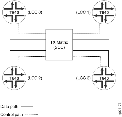
A routing matrix can have up to four LCCs, and each LCCs has up to eight FPCs. Therefore, the routing matrix as a whole can have up to 32 FPCs (0 through 31).
In the Junos OS CLI, an interface name has the following format:
type-fpc/pic/port
When you specify the fpc number for a router in a
routing matrix, the Junos OS determines which LCCs contains the specified FPC based
on the following assignment:
-
On LCC 0, FPC hardware slots 0 through 7 are configured as 0 through 7.
-
On LCC 1, FPC hardware slots 0 through 7 are configured as 8 through 15.
-
On LCC 2, FPC hardware slots 0 through 7 are configured as 16 through 23.
-
On LCC 3, FPC hardware slots 0 through 7 are configured as 24 through 31.
For example, the 1 in se-1/0/0 refers to FPC
hardware slot 1 labeled lcc0. The 11 in
t1-11/2/0 refers to FPC hardware slot 3 labeled
lcc1. The 20 in so-20/0/1
refers to FPC hardware slot 4 labeled lcc2. The 31
in t3-31/1/0 refers to FPC hardware slot 7 labeled
lcc3.
Chassis Interface Naming
You configure some PIC properties, such as framing, at the [edit
chassis] hierarchy level. Chassis interface naming varies, depending on
the routing hardware.
-
To configure PIC properties for a standalone router, you must specify the FPC and PIC numbers, as follows:
[edit chassis] fpc slot-number { pic pic-number { ... } } -
To configure PIC properties for a router configured in a routing matrix, you must specify the LCC, FPC, and PIC numbers, as follows:
[edit chassis]
lcc lcc-number {
    fpc slot-number { # Use the hardware FPC slot number
        pic pic-number {
            ...
        }
    }
}
For more information about the [edit chassis]
hierarchy, see the [edit chassis].
Examples: Interface Naming
This section provides examples of naming interfaces with an illustration of where slots, PICs, and ports are located.
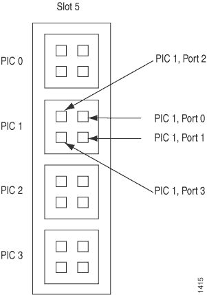
For an FPC in slot 1 with two OC3 SONET/SDH PICs in PIC positions 0 and 1, each PIC with two ports uses the following names:
so-1/0/0.0
so-1/0/1.0
so-1/1/0.0
so-1/1/1.0
An OC48 SONET/SDH PIC in slot 1 and in concatenated mode appears as a single FPC with a single PIC, which has a single port. If this interface has a single logical unit, it has the following name:
so-1/0/0.0
An OC48 SONET/SDH PIC in slot 1 and in channelized mode has a number for each channel. For example:
so-1/0/0:0
so-1/0/0:1
For an FPC in slot 1 with a Channelized OC12 PIC in PIC position 2, the DS3 channels have the following names:
t3-1/2/0:0
t3-1/2/0:1
t3-1/2/0:2
...
t3-1/2/0:11
For an FPC in slot 1 with four OC12 ATM PICs (the FPC is fully populated), the four PICs, each with a single port and a single logical unit, have the following names:
at-1/0/0.0
at-1/1/0.0
at-1/2/0.0
at-1/3/0.0
In a routing matrix labeled lcc1, for an FPC in slot 5 with four
SONET OC192 PICs, the four PICs, each with a single port and a single logical unit,
have the following names:
so-13/0/0.0
so-13/1/0.0
so-13/2/0.0
so-13/3/0.0
For an FPC in slot 1 with one 4-port ISDN BRI interface card, port 4 has the following name:
br-1/0/4
The first B-channel, the second B-channel, and the control channel have the following names:
bc-1/0/4:1
bc-1/0/4:2
dc-1/0/4:0
See Also
Interface Types
Interfaces that are used for networking or services:
-
Permanent interfaces—Interfaces that are always present in the device.
Permanent interfaces in the device consist of management Ethernet interfaces and internal Ethernet interfaces, both of which are described separately in the following topics:
-
Understanding Management Ethernet Interfaces, see Management Ethernet Interfaces Overview.
-
Understanding Internal Ethernet Interfaces
-
-
Transient interfaces—Interfaces that can be inserted into or removed from the device depending on your network configuration needs.
-
Networking interfaces—Interfaces that primarily provide traffic connectivity.
-
Services interfaces—Interfaces that provide specific capabilities for manipulating traffic before it is delivered to its destination.
-
Container interfaces—Interfaces that support automatic protection switching (APS) on physical SONET links using a virtual container infrastructure.
Junos OS internally generates nonconfigurable interfaces, which are described in Services Interfaces Overview for Routing Devices.
Transient Interfaces
The routers contain slots for installing Flexible PIC Concentrator [FPC] or Dense Port Concentrator [DPC] or Modular Port Concentrator [MPC]. Physical Interface Card [PIC] can be installed in FPCs. Modular Interface Card [MIC] can be inserted into MPCs.
The number of PICs that can be installed varies by device and type of FPC. The PICs provide the actual physical interfaces to the network. The routers contain slots for installing either DPC boards that provide the physical interfaces to the network or for installing FPCs in which PICs can be installed.
You can insert any DPC or FPC into any slot that supports them in the router. Typically, you can place any combination of PICs, compatible with your router, in any location on an FPC. (You are limited by the total FPC bandwidth, and by the fact that some PICs physically require two or four of the PIC locations on the FPC. In some cases, power limitations or microcode limitations may also apply.) To determine DPC and PIC compatibility, see the see your router’s Interface Module Reference.
You can insert MPC into any slot that supports them in the appropriate router. You can install up to two MICs of different media types in the same MPC as long as the MPC supports those MICs.
These physical interfaces are transient interfaces of the router. They are referred to as transient because you can hot-swap a DPC or FPC or MPC and its PICs or MICs at any time.
You must configure each transient interface based on the slot in which the FPC or DPC or MPC is installed, the location in which the PIC or MIC is installed, and for multiple port PICs or MICs , the port to which you are connecting.
You can configure the interfaces on PICs or MICs that are already installed in the router as well as interfaces on PICs or MICs that you plan to install later. The Junos OS detects which interfaces are actually present, so when the software activates its configuration, it activates only the present interfaces and retains the configuration information for the interfaces that are not present. When the Junos OS detects that an FPC containing PICs or MPC containing MICs has been inserted into the router, the software activates the configuration for those interfaces.
Services Interfaces
Services interfaces enable you to incrementally add services to your network. The Junos OS supports the following services PICs:
Adaptive Services (AS) PICs—Enable you to provide multiple services on a single PIC by configuring a set of services and applications. The AS PICs offer a special range of services that you configure in one or more service sets.
ES PIC—Provides a security suite for the IP version 4 (IPv4) and IP version 6 (IPv6) network layers. The suite provides functionality such as authentication of origin, data integrity, confidentiality, replay protection, and nonrepudiation of source. It also defines mechanisms for key generation and exchange, management of security associations, and support for digital certificates.
Monitoring Services PICs—Enable you to monitor traffic flow and export the monitored traffic. Monitoring traffic enables you to gather and export detailed information about IPv4 traffic flows between source and destination nodes in your network; sample all incoming IPv4 traffic on the monitoring interface and present the data in cflowd record format; perform discard accounting on an incoming traffic flow; encrypt or tunnel outgoing cflowd records, intercepted IPv4 traffic, or both; and direct filtered traffic to different packet analyzers and present the data in its original format. On a Monitoring Services II PIC, you can configure either monitoring interfaces or collector interfaces. A collector interface enables you to combine multiple cflowd records into a compressed ASCII data file and export the file to an FTP server.
Multilink Services, MultiServices, Link Services, and Voice Services PICs—Enable you to split, recombine, and sequence datagrams across multiple logical data links. The goal of multilink operation is to coordinate multiple independent links between a fixed pair of systems, providing a virtual link with greater bandwidth than any of the members.
Tunnel Services PIC—By encapsulating arbitrary packets inside a transport protocol, tunneling provides a private, secure path through an otherwise public network. Tunnels connect discontinuous subnetworks and enable encryption interfaces, virtual private networks (VPNs), and Multiprotocol Label Switching (MPLS).
On routers, logical tunnel interfaces enable you to connect logical systems, virtual routers, or VPN instances. For more information about VPNs, see the Layer 2 VPNs and VPLS User Guide for Routing Devices.
Container Interfaces
Container interfaces provide the following features:
-
Automatic protection switching (APS) on SONET/SDH and ATM links are supported using the container infrastructure.
-
Container physical interfaces and logical interfaces remain up on switchover.
-
APS parameters are auto-copied from the container interface to the member links.
Container interfaces features are described in the following sections:
- Traditional APS Concept
- Container Interfaces Concept
- APS Support for Container-Based Interfaces
- Autocopy of APS Parameters
Traditional APS Concept
Traditional Automatic Protection Switching (APS) is configured on two independent physical SONET/SDH interfaces: one interface is configured as the working circuit and the other is configured as the protect circuit (see Figure 3). The circuit, named Circuit X in the figure, is the link between the two SONET interfaces.
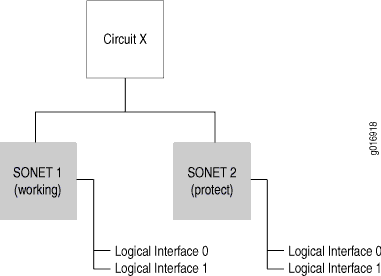
Traditional APS uses routing protocols that run on each individual SONET/SDH interface (since circuit is an abstract construct, instead of being an actual interface). When the working link goes down, the APS infrastructure brings up the protect link and its underlying logical interfaces and brings down the working link and its underlying logical interfaces, causing the routing protocols to reconverge. This consumes time and leads to traffic loss even though the APS infrastructure has performed the switch quickly.
Container Interfaces Concept
To solve the problem of traffic loss, the Junos OS provides a soft interface construct called a container interface (see Figure 4).
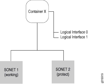
The container interface allows routing protocols to run on the logical interfaces associated with a virtual container interface instead of on the physical SONET/SDH and ATM interfaces. When APS switches the underlying physical link based on a fault condition, the container interface remains up, and the logical interface on the container interface does not flap. The routing protocols remain unaware of the APS switching.
APS Support for Container-Based Interfaces
With the container interface, APS is configured on the container interface itself. Individual member SONET/SDH and ATM links are either marked as primary (corresponding to the working circuit) or standby (corresponding to the protect circuit) in the configuration. No circuit or group name is specified in the container interface model; physical SONET/SDH and ATM links are put in an APS group by linking them to a single container interface. APS parameters are specified at the container interface level and are propagated to the individual SONET/SDH and ATM links by the APS daemon.
Autocopy of APS Parameters
Typical applications require copying APS parameters from the working circuit to the protect circuit, since most of the parameters must be the same for both circuits. This is automatically done in the container interface. APS parameters are specified only once under the container physical interface configuration and are internally copied over to the individual physical SONET/SDH and ATM links.
See Also
Internal Ethernet Interfaces
Internal Ethernet interfaces provide communication between the Routing Engine and the Packet Forwarding Engines. Junos OS automatically configures internal Ethernet interfaces when Junos OS boots. Junos OS boots the packet-forwarding component hardware. When these components run, the Control Board (CB) uses the internal Ethernet interface to transmit hardware status information to the Routing Engine. Hardware status information includes the internal router temperature, the condition of the fans, whether an FPC has been removed or inserted, and information from the LCD on the craft interface.
To determine the supported internal Ethernet interfaces for your router, see Supported Routing Engines by Router.
Don't modify or remove the configuration for the internal Ethernet interface that Junos OS automatically configures. If you do, the device stops functioning.
-
Most Juniper devices—Junos OS creates the internal Ethernet interface. The internal Ethernet interface connects the Routing Engine
re0to the Packet Forwarding Engines.If the device has redundant Routing Engines, another internal Ethernet interface is created on each Routing Engine (
re0andre1) in order to support fault tolerance. Two physical links betweenre0andre1connect the independent control planes. If one of the links fails, both Routing Engines can use the other link for IP communication. -
LCC in a routing matrix—On an LCC configured in a routing matrix, the Routing Engine and Control Board function as a unit, or host subsystem. For each host subsystem in the LCC, the Junos OS automatically creates two internal Ethernet interfaces,
bcm0andem1, for the two Gigabit Ethernet ports on the Routing Engine.The
bcm0interface connects the Routing Engine in each LCC to the Routing Engines of every other LCC configured in the routing matrix.-
The Routing Engine connects to a Gigabit Ethernet switch on the local Control Board.
-
The switch connects the Control Board to the remote Routing Engines of every other LCC configured in the routing matrix.
If an LCC in a routing matrix contains redundant host subsystems, the independent control planes are connected by two physical links between the Gigabit Ethernet ports on their respective Routing Engines.
-
The primary link to the remote Routing Engine is at the
bcm0interface; the Gigabit Ethernet switch on the local Control Board also connects the Routing Engine to the Gigabit Ethernet port accessed by theem1interface on the remote Routing Engine. -
The alternate link to the remote Routing Engine is at the
em1interface. This second port connects the Routing Engine to the Gigabit Ethernet switch on the remote Control Board, which connects to the Gigabit Ethernet port at thebcm0interface on the remote Routing Engine.
If one of the two links between the host subsystems fails, both Routing Engines can use the other link for IP communication.
-
Each device also has one or two serial ports, labeled CON (console) or AUX (auxiliary), for connecting tty type terminals to the device using standard PC-type tty cables. Although these ports are not network interfaces, they do provide access to the device. Refer to your devices hardware guide for details.
See Also
Interface Encapsulations
Table 1 lists encapsulation support by interface type.
Interface Type |
Physical Interface Encapsulation |
Logical Interface Encapsulation |
|---|---|---|
|
|
|
|
|
|
|
NA |
|
|
|
|
|
|
|
|
|
|
NA |
NA |
|
|
NA |
NA |
|
|
|
|
|
|
|
|
|
|
NA |
NA |
|
|
|
|
|
|
|
|
|
|
NA |
NA |
|
|
|
|
|
|
NA |
NA |
|
Ethernet interfaces |
|
|
|
|
NA |
NA |
|
|
NA |
NA |
|
|
|
|
|
|
|
|
|
|
NA |
|
|
|
NA |
|
|
|
|
|
|
|
|
|
|
|
|
|
|
|
|
|
|
Controller-level channelized IQ interfaces ( |
NA |
NA |
|
Services interfaces ( |
NA |
NA |
|
Unconfigurable, internally generated interfaces
( |
NA |
NA |
Interface Descriptors
When you configure an interface, you are effectively specifying the properties for a physical interface descriptor. In most cases, the physical interface descriptor corresponds to a single physical device and consists of the following parts:
-
The interface name, which defines the media type
-
The slot in which the FPC is located
-
The location on the FPC in which the PIC is installed
-
The PIC port
-
The interface’s channel and logical unit numbers (optional)
Each physical interface descriptor can contain one or more logical interface descriptors. These descriptors enable you to map one or more logical (or virtual) interfaces to a single physical device. Creating multiple logical interfaces enables you to associate multiple virtual circuits, data-link connections, or virtual LANs (VLANs) with a single interface device.
Each logical interface descriptor can have one or more family descriptors to define the protocol family that is associated with and allowed to run over the logical interface.
The following protocol families are supported:
-
Internet Protocol version 4 (IPv4) suite (inet)
-
Internet Protocol version 6 (IPv6) suite (inet6)
-
Ethernet (ethernet switching)
-
Circuit cross-connect (CCC)
-
Translational cross-connect (TCC)
-
International Organization for Standardization (ISO)
-
Multilink Frame Relay end-to-end (MLFR end-to-end)
-
Multilink Frame Relay user-to-network interface network-to-network interface (MLFR UNI NNI)
-
Multilink Point-to-Point Protocol (MLPPP)
-
Multiprotocol Label Switching (MPLS)
-
Trivial Network Protocol (TNP)
-
(Routers only) Virtual private LAN service (VPLS)
Finally, each family descriptor can have one or more address entries, which associate a network address with a logical interface and hence with the physical interface.
You configure the various interface descriptors as follows:
-
You configure the physical interface descriptor by including the
interfaces interface-namestatement. -
You configure the logical interface descriptor by including the
unitstatement within theinterfaces interface-namestatement or by including the.logicaldescriptor at the end of the interface name, as inet-0/0/0.1, where the logical unit number is 1, as shown in the following examples:[edit] user@host# set interfaces et-0/0/0 unit 1 [edit] user@host# edit interfaces et-0/0/0.1 [edit interfaces et-0/0/0] user@host# set unit 1
-
You configure the family descriptor by including the
familystatement within theunitstatement. -
You configure address entries by including the
addressstatement within thefamilystatement. -
You configure tunnels by including the
tunnelstatement within theunitstatement.
The address of a logical interface cannot be the same as a tunnel interface’s source or destination address. If you try to configure a logical interface with a tunnel interface’s address or vice versa, a commit failure will occur.
See Also
Physical Part of an Interface Name
When you display information about an interface, you specify the interface type, the slot in which the Flexible PIC Concentrator (FPC) is installed, the slot on the FPC in which the Physical Interface Card (PIC) is located, and the configured port number.
Some Juniper devices do not have actual PICs. Instead, they have built-in network ports on
the front panel of the router. These ports are named using the same naming convention used for
devices with PICs with the understanding that the FPC, PIC, and port are pseudo devices. When
you display information about one of these ports, you specify the interface type, the slot for
the Flexible PIC Concentrator (FPC), the slot on the FPC for the Physical Interface
Card (PIC), and the configured port number. In the CLI, all PICs are represented as
pic0.
In the physical part of the interface name, a hyphen (-) separates the media type (for example, et) from the FPC number. A slash (/) separates the FPC, PIC, and port numbers. A colon (:) separates the port number and channel (optional):
type-fpc/pic/port[:channel]
-
fpc—Slot in which the DPC, FPC, or MPC is installed.
-
pic—Slot on the FPC in which the PIC is located.
For DPCs, MICs, and the 16-port MPC, the PIC value is a logical grouping of ports and varies on different platforms.
-
port—Port number on the DPC, PIC, MPC, or MIC.
On routers when you display information about an interface, you specify the interface type, the Dense Port Concentrator (DPC), Flexible PIC Concentrator (FPC), or Modular Port Concentrator (MPC) slot, the PIC or MIC slot, and the configured port number.
Display Interface Configurations
To display a configuration, use either the show command in configuration
mode or the show configuration top-level command. Interfaces are listed
in numerical order, first from lowest to highest slot number, and then from lowest to
highest PIC number, and finally from lowest to highest port number.