Inline IPsec
Inline IPsec-Overview
The IPsec architecture provides a security suite for the IP version 4 (IPv4) and IP version 6 (IPv6) network layers. The suite offers authentication of origin, data integrity, confidentiality, replay protection, and non-repudiation of source.
The Inline IPsec architecture comprises of a special IPsec engine block that supports IPsec operations. The PFE (Packet Forwarding Engine) is capable of performing IPsec encryption or decryption inline within the PFE without the need of offloading to a services card. Hence, inline IPsec can achieve higher throughput.
- Salient Features of Inline IPsec Data Plane
- Security Associations
- IKE
- Dead-Peer-Detection (DPD)
- NAT-T
- IPsec WAN Connectivity
Salient Features of Inline IPsec Data Plane
The following are the salient features of IPsec data plane
-
Supports both IPv4 and IPv6 IPsec protocols
-
Supports 128-bit key and 256-bit key AES-GCM
-
Supports up to 2000 tunnels per chassis
-
Each forwarding ASIC supports two Packet Forwarding Engines. Starting with Junos OS Release 24.4R1, both the Packet Forwarding engines can be configured, supporting up to 600Gbps half-duplex (300Gbps half-duplex per PFE).
For details on platform and Junos version support, see Feature Explorer.
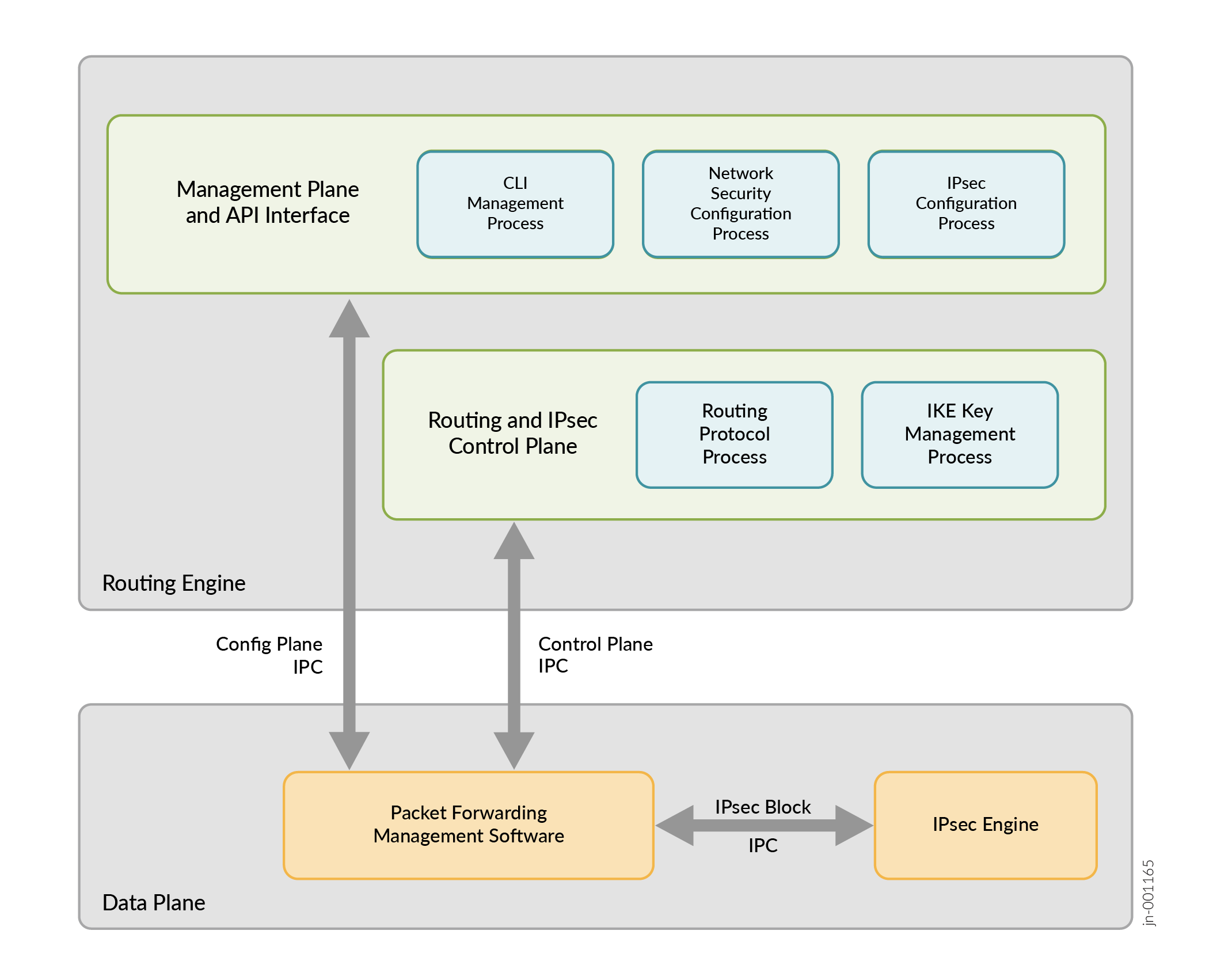
Figure 1 illustrates the architecture of inline IPsec data plane, control plane, and management plane and API interface.
Inline services interfaces are virtual interfaces that reside on the Packet Forwarding Engine. For more information see, Enabling Inline Service Interfaces
The MX series routers that support inline IPsec services, do not use a services card like MS-MPC or SPC3, Instead, you can configure inline IPsec services on the MPCs using the naming convention si-fpc/pic/port. However, in order to configure the inline IPsec services, you must enable the Next Gen Services on the MX series router. See Unified-Services Framework for more information.
You can configure inline services with four si ifds per PIC in the
format, si/fpc/pic/port-number. If the fpc is 0, and pic 0, you can
have four si ifds – si-0/0/0,
si-0/0/1 , si-0/0/2 and si-0/0/3.
The following features are supported:
-
ESP tunnel mode with AES-128-GCM and AES-256-GCM for IPsec SA for both IPv4 and IPv6 encapsulations.
-
32 bit and Extended Sequence number (64 bit).
-
IKEV2 with local and remote identities, re-auth, authentication using x509 certificates, IKE fragmentation.
-
Dead-Peer-Detection
-
Tunnel-MTU per VPN is supported. If the IPsec packet exceeds the configured MTU, the packet is pre-fragmented and then ESP encapsulated. This prevents fragmentation after ESP encapsulation.
-
SA lifetime in seconds (IKE and IPsec rekey).
-
UDP encapsulation of ESP packets.
The following features are not supported:
-
Authentication Header (AH)
-
Transport mode
-
Reassembly of IPv4 packets prior to decryption
-
Null encryption as per RFC4543
-
IKE-V1
The IPsec and IKE Features Supported for Inline IPsec lists the supported IPsec and IKE features for inline IPsec:
|
Feature |
Applicable to IKE |
Applicable to IPsec |
|---|---|---|
|
MD5 |
Yes |
No |
|
SHA-256 |
Yes |
No |
|
SHA-384 |
Yes |
No |
|
SHA-512 |
Yes |
No |
|
AES-128-GCM |
Yes |
Yes |
|
AES-256-GCM |
Yes |
Yes |
|
3DES-CBC |
Yes (Not recommended) |
No |
|
AES-128-CBC |
Yes |
No |
|
AES-192-CBC |
Yes |
No |
|
AES-256-CBC |
Yes |
No |
|
DES-CBC |
Yes (Not recommended) |
No |
A Security Association (SA) is a simplex connection that enables two hosts to communicate with each other securely by means of IPsec. An SA encapsulates the encryption and integrity algorithms, cryptographic keys, security policy, and the lifetime of the SA. An IKE SA contains attributes for establishing an IPsec SA whereas an IPsec SA defines the attributes for encrypting the actual data traffic.
ike-key-managment-daemon (IKED), a Junos RE daemon, maintains the lifetime of IKE and IPsec SAs. An IKE configuration defines the algorithms and keys used to establish a secure connection with a peer security gateway.
You may encounter packet drops following an IPsec rekey. To mitigate this issue, it is recommended to set different lifetime seconds on each IPsec peer to avoid simultaneous rekey events. The IPsec rekey initiation occurs at the soft lifetime expiry, which is slightly before the configured lifetime-seconds. For instance, if one side is set to 86,400 seconds, the other side should have a lifetime configuration ranging between 83,000 to 84,000 seconds to minimize the chances of simultaneous rekey.
Additionally, for Inline IPsec, configuring the install-interval
according to the network's characteristics may be necessary to achieve a lossless
rekey process. It is advisable to set the install-interval to a
value that best suits the network to prevent packet loss during rekey, especially in
scenarios where network latency is a concern.
Security Associations
To use IPsec security services, you create SAs between two end-points. An SA is a simplex connection that enables two hosts to communicate with each other securely by means of IPsec. There are two types of SAs:
-
Manual SAs require no negotiation; all values, including the keys, are static and specified in the configuration. Manual SAs statically define the security parameter index (SPI) values, algorithms, and keys to be used, and require matching configurations on both ends of the tunnel. Each peer must have the same configured options for communication to take place.
-
Dynamic SAs require additional configuration. . IKE creates dynamic security associations; it negotiates SAs for IPsec. The IKE configuration defines the algorithms and keys used to establish the secure IKE connection with the peer security gateway. This connection is then used to dynamically agree upon keys and other data used by the dynamic IPsec SA. The IKE SA is negotiated first and then used to protect the negotiations that determine the dynamic IPsec SAs.
IKE
IKE is a key management protocol that creates dynamic SAs; it negotiates SAs for IPsec. An IKE configuration defines the algorithms and keys used to establish a secure connection with a peer security gateway.
IKE performs the following tasks:
-
Negotiates and manages IKE and IPsec parameters.
-
Authenticates secure key exchange.
-
Provides mutual peer authentication by means of shared secrets (not passwords) and public keys.
-
Provides identity protection (in main mode).
Inline IPsec only supports IKE version 2 (IKE v2). IKE negotiates security attributes and establishes shared secrets to form the bidirectional IKE SA. After IKE SAs are negotiated, inbound and outbound IPsec SAs are established, and the IKE SA secures the exchange of IPsec SA. IKE also generates keying material, provides Perfect Forward Secrecy, and exchanges identities.
In responder-only mode, the MX Series router does not initiate IKE negotiations, it only responds to IKE negotiations initiated by the peer gateway. This might be required while inter-operating with other vendor’s equipment, such as Cisco devices. Because the MX Series does not support the protocol and port values in the traffic selector, it cannot initiate an IPsec tunnel to another vendor’s peer gateway that expects these values. By configuring the response-only mode on the MX Series, the MX can accept the traffic selector in the IKE negotiation initiated from the peer gateway.
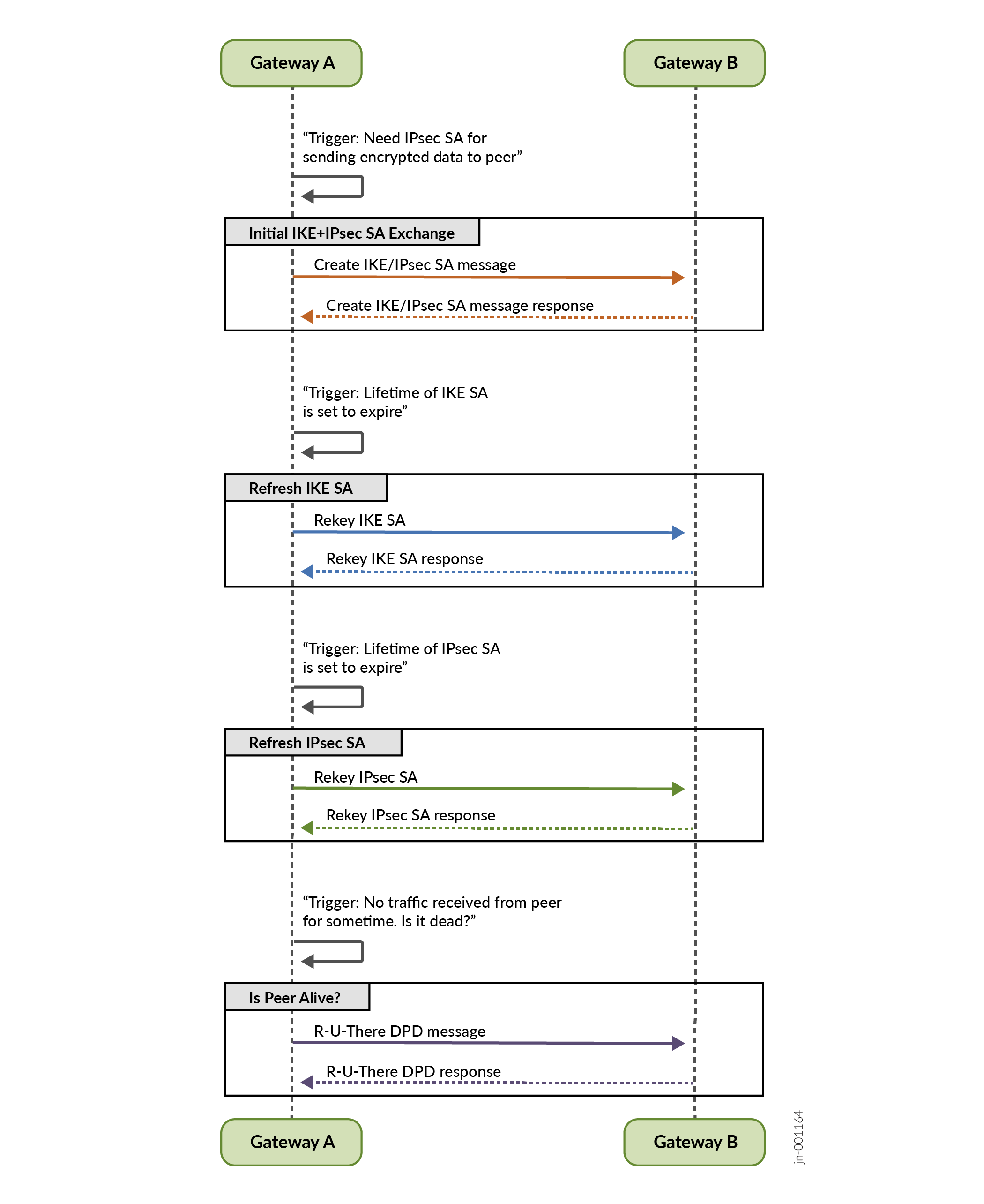
Figure 2 illustrates the IPsec SA and IKE exchange between peer gateways.
Dead-Peer-Detection (DPD)
DPD is a method used to verify the liveliness of the IKE peer to avoid blackholing of IPsec traffic. A device performs this verification by periodically sending DPD probes (R-U-THERE message) and waiting for DPD response (R-U-THERE-ACK message).
You can configure DPD in the following modes:
-
always-send—Instructs the device to send DPD probe at regular interval regardless of whether there is outgoing IPsec traffic to the peer.
-
optimized—Send DPD probe if there is no incoming IKE or IPsec traffic within the configured interval after outgoing packets are sent to the peer. This is the default DPD mode.
-
probe-idle-tunnel—Send DPD probe during idle traffic time between peers.
NAT-T
Network Address Translation-Traversal (NAT-T) is a method used for managing IP address translation-related issues encountered when the data protected by IPsec passes through a device configured with NAT for address translation
IPsec WAN Connectivity
MX series routers that support inline IPsec have two Packet Forwarding Engines (PFEs) slices per YT ASIC. Each PFE slice is capable of up to 800Gbps of bandwidth. Each PFE slice has two Port Groups (PG), for a total of four PGs per YT
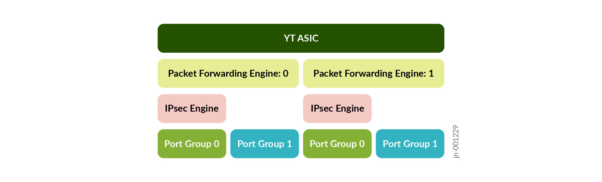
Each PG supports up to 400Gbps of bandwidth for WAN connectivity for regular (non-IPsec traffic). Port group 0 of each PFE slice can support IPsec.
Each port group that supports IPsec can support up to 300 Gbps WAN connectivity for IPsec traffic whereas the remaining 100Gbps can be used for non-IPsec traffic.
You can use the show chassis fpc slot-number pic
slot-number
to display the port-group information and the WAN connectivity status of a
port.
|
Platform |
Difference |
|---|---|
|
MX304 |
Supports graceful LMIC online insertion and removal |
|
MX301, MX304, and MX10008 |
Supports QKD. See Quantum Security Overview for more information. |
See Also
Example: Configuring Point-to-Point Inline IPSec Tunnel
This example shows how to configure point-to-point inline IPsec tunnel to allow data to be securely transferred between two sites.
Requirements
This example uses the following hardware and software components:
-
MX304 device with Unified Services enabled and the required license support. To enable Unified-Services on the device, execute
request system
                            enable unified-services
from the CLI and reboot the device. For more details, see (Unified-Services Framework). -
Junos OS Release 24.2R1 or later for MX Series routers
Overview
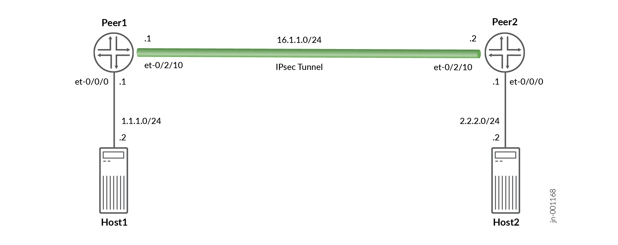
Figure 1 illustrates a topology with Inline IPSec Tunnel established between two MX304 peers (Peer1 and Peer2). In this example, you configure a route-based VPN on Peer1 (MX304) and Peer2 (MX304). Host1 and Host2 use the VPN to send traffic securely over the Internet between both hosts.
In this example, you configure inline-services (to enable inline services on the PIC), service-set, security policy, interfaces, and an IPv4 default route. See Table 3 through Table 7 for specific configuration parameters used in this example.
|
Feature |
Configuration Parameters |
|---|---|
|
inline-services |
inline-services |
|
Feature |
Name |
Configuration Parameters |
|---|---|---|
|
service-set |
ss1 |
inside-service-interface (si-0/0/0.) outside-service-interface (si-0/0/0.1) ipsec-vpn is ipsec_vpn |
|
Feature |
Name |
Configuration Parameters |
|---|---|---|
|
Proposal |
ike_prop |
Authentication method: pre-shared-keys |
|
Policy |
ike_policy |
|
|
Gateway |
ike_gw |
|
|
Feature |
Name |
Configuration Parameters |
|---|---|---|
|
Proposal |
ike_prop |
|
|
Policy |
ike_policy |
|
|
VPN |
ipsec_vpn |
|
|
Feature |
Name |
Configuration Parameters |
|---|---|---|
|
Interfaces |
|
|
|
Static Routes |
2.2.2.0/24 |
Next hop is st0.1 |
Configuration
In this example, you enable the inline services, configure the service-set parameters, IKE and IPsec configuration parameters, and interface and static route configuration for Peer1. You can use the same configuration with change in IPSec gateway address, interface addresses etc on Peer2.
CLI Quick Configuration
To quickly configure this example, copy the following commands, paste them in a
text file, remove any line breaks, change any details necessary to match your
network configuration, and then copy and paste the commands into the CLI at the
[edit] hierarchy level:
set chassis fpc 0 pic 0 inline-services
set services service-set ss1 next-hop-service inside-service-interface si-0/0/0.0
set services service-set ss1 next-hop-service outside-service-interface si-0/0/0.1
set services service-set ss1 ipsec-vpn ipsec_vpn
set security ike proposal ike_prop description "IKE Proposal"
set security ike proposal ike_prop authentication-method pre-shared-keys
set security ike policy ike_policy mode main
set security ike policy ike_policy proposals ike_prop
set security ike policy ike_policy pre-shared-key ascii-text "test123"
set security ike gateway ike_gw ike-policy ike_policy
set security ike gateway ike_gw address 16.1.1.1
set security ike gateway ike_gw external-interface et-0/2/10
set security ike gateway ike_gw local-address 16.1.1.2
set security ike gateway ike_gw version v2-only
set security ipsec proposal ipsec_prop description "IPSec Proposal"
set security ipsec proposal ipsec_prop protocol esp
set security ipsec proposal ipsec_prop encryption-algorithm aes-256-gcm
set security ipsec policy ipsec_policy proposals ipsec_prop
set security ipsec vpn ipsec_vpn bind-interface st0.1
set security ipsec vpn ipsec_vpn copy-outer-dscp
set security ipsec vpn ipsec_vpn ike gateway ike_gw
set security ipsec vpn ipsec_vpn ike ipsec-policy ipsec_policy
set security ipsec vpn ipsec_vpn ike install-interval 3
set security ipsec vpn ipsec_vpn establish-tunnels immediately
set interfaces et-0/0/0 unit 0 family inet address 1.1.1.1/24
set interfaces si-0/0/0 unit 0 family inet
set interfaces si-0/0/0 unit 0 family inet6
set interfaces si-0/0/0 unit 0 service-domain inside
set interfaces si-0/0/0 unit 1 family inet
set interfaces si-0/0/0 unit 1 family inet6
set interfaces si-0/0/0 unit 1 service-domain outside
set interfaces et-0/2/10 unit 0 family inet address 16.1.1.2/24
set interfaces st0 unit 1 family inet
set routing-options static route 2.2.2.0/24 next-hop st0.1
Step-by-Step Procedure
The following example requires you to navigate various levels in the configuration hierarchy. For information about navigating the CLI, see Using the CLI Editor in Configuration Mode in the Junos OS CLI User Guide
To configure Inline IPsec on the MX304 router:
-
Enable inline-services.
[edit]
user@host# set chassis fpc 0 pic 0 inline-services
-
Configure a service-set
[edit]
user@host# set services service-set ss1 next-hop-service inside-service-interface si-0/0/0.0
user@host# set services service-set ss1 next-hop-service outside-service-interface si-0/0/0.1
user@host# set services service-set ss1 ipsec-vpn ipsec_vpn
-
Configure security IKE proposal
[edit]
user@host# set security ike proposal ike_prop description "IKE Proposal"
user@host# set security ike proposal ike_prop authentication-method pre-shared-keys
-
Configure security IKE policy
[edit]
user@host# set security ike policy ike_policy mode main
user@host# set security ike policy ike_policy proposals ike_prop
user@host# set security ike policy ike_policy pre-shared-key ascii-text test123
-
Configure security IKE gateway
[edit]
user@host# set security ike gateway ike_gw ike-policy ike_policy
user@host# set security ike gateway ike_gw address 16.1.1.1
user@host# set security ike gateway ike_gw external-interface et-0/2/10
user@host# set security ike gateway ike_gw local-address 16.1.1.2
user@host# set security ike gateway ike_gw version v2-only
-
Configure security IPsec proposal
[edit]
user@host# set security ipsec proposal ipsec_prop description "IPSec Proposal"
user@host# set security ipsec proposal ipsec_prop protocol esp
user@host# set security ipsec proposal ipsec_prop encryption-algorithm aes-256-gcm
-
Configure security IPsec policy
[edit]
user@host# set security ipsec policy ipsec_policy proposals ipsec_prop
-
Configure security IPsec VPN
[edit]
user@host# set security ipsec vpn ipsec_vpn bind-interface st0.1
user@host# set security ipsec vpn ipsec_vpn copy-outer-dscp
user@host# set security ipsec vpn ipsec_vpn ike gateway ike_gw
user@host# set security ipsec vpn ipsec_vpn ike ipsec-policy ipsec_policy
user@host# set security ipsec vpn ipsec_vpn ike install-interval 3
user@host# set security ipsec vpn ipsec_vpn establish-tunnels immediately
-
Configure interfaces.
[edit]
user@host# set interfaces et-0/0/0 unit 0 family inet address 1.1.1.1/24
user@host# set interfaces si-0/0/0 unit 0 family inet
user@host# set interfaces si-0/0/0 unit 0 family inet6
user@host# set interfaces si-0/0/0 unit 0 service-domain inside
user@host# set interfaces si-0/0/0 unit 1 family inet
user@host# set interfaces si-0/0/0 unit 1 family inet6
user@host# set interfaces si-0/0/0 unit 1 service-domain outside
user@host# set interfaces et-0/2/10 unit 0 family inet address 16.1.1.2/24
user@host# set interfaces st0 unit 1 family inet
user@host# set interfaces st0 unit 1 family inet6
-
Configure static-route
[edit]
user@host# set routing-options static route 2.2.2.0/24 next-hop st0.1
Results
In the configuration mode, confirm your configuration by entering the
show security ike and show security ipsec
commands. If the output does not display the intended configuration, repeat the
configuration instructions in this example to correct it.
[edit security ike]
root@peer1# show
proposal ike_prop {
    description "IKE Proposal";
    authentication-method pre-shared-keys;
}
policy ike_policy {
    mode main;
    proposals ike_prop;
    pre-shared-key ascii-text "$9$OY8RBcl8LNbYo7-"; ## SECRET-DATA
}
gateway ike_gw {
    ike-policy ike_policy;
    address 16.1.1.1;
    external-interface et-0/2/10;
    local-address 16.1.1.2;
    version v2-only;
}
gateway ike_gwv6 {
    ike-policy ike_policy;
    address 1611::1;
    external-interface et-0/2/10;
    local-address 1611::2;
    version v2-only;
}
[edit security ipsec]
root@peer1# show
proposal ipsec_prop {
    description "IPSec Proposal";
    protocol esp;
    encryption-algorithm aes-256-gcm;
}
policy ipsec_policy {
    proposals ipsec_prop;
}
vpn ipsec_vpn {
    bind-interface st0.1;
    ike {
        gateway ike_gw;
        ipsec-policy ipsec_policy;
    }
    establish-tunnels immediately;
}
Verification
Perform these tasks to confirm that the Inline IPsec configuration is working properly
- Verify the IKE Status
- Verifying the IPsec Status
- Test Traffic Over IPSec Tunnel
- Review IPsec Traffic Statistics and Errors Globally
Verify the IKE Status
Purpose
Verify the status of IKE.
Action
In operational mode, enter the show security ike
security-associations command. After obtaining an index number
from the command, use the show security ike security-associations
index index_number detail command.
user@host> show security ike security-associations Index State Initiator cookie Responder cookie Mode Remote Address 1 UP 422250f57a089b14 02ae4230bbf3c3fc IKEv2 16.1.1.1
user@host> show security ike security-associations index 1 Index State Initiator cookie Responder cookie Mode Remote Address 1 UP 422250f57a089b14 02ae4230bbf3c3fc IKEv2 16.1.1.1
user@host> show security ike security-associations index 1 detail
IKE peer 16.1.1.1, Index 1, Gateway Name: ike_gw
Role: Responder, State: UP
Initiator cookie: 422250f57a089b14, Responder cookie: 02ae4230bbf3c3fc
Exchange type: IKEv2, Authentication method: Pre-shared-keys
Local gateway interface: et-0/2/10.0
Routing instance: default
Local: 16.1.1.2:500, Remote: 16.1.1.1:500
Lifetime: Expires in 14789 seconds
Reauth Lifetime: Disabled
IKE Fragmentation: Enabled, Size: 576
Remote Access Client Info: Unknown Client
Peer ike-id: 16.1.1.1
AAA assigned IP: 0.0.0.0
PPK-profile: None
Algorithms:
Authentication : hmac-sha1-96
Encryption : 3des-cbc
Pseudo random function: hmac-sha1
Diffie-Hellman group : DH-group-2
Traffic statistics:
Input bytes : 1778
Output bytes : 1706
Input packets: 10
Output packets: 10
Input fragmented packets: 0
Output fragmented packets: 0
IPSec security associations: 10 created, 4 deleted
Phase 2 negotiations in progress: 1
IPSec Tunnel IDs: 500001
Negotiation type: Quick mode, Role: Responder, Message ID: 0
Local: 16.1.1.2:500, Remote: 16.1.1.1:500
Local identity: 16.1.1.2
Remote identity: 16.1.1.1
Flags: IKE SA is created
IPsec SA Rekey CREATE_CHILD_SA exchange stats:
Initiator stats: Responder stats:
Request Out : 0 Request In : 4
Response In : 0 Response Out : 4
No Proposal Chosen In : 0 No Proposal Chosen Out : 0
Invalid KE In : 0 Invalid KE Out : 0
TS Unacceptable In : 0 TS Unacceptable Out : 0
Res DH Compute Key Fail : 0 Res DH Compute Key Fail: 0
Res Verify SA Fail : 0
Res Verify DH Group Fail: 0
Res Verify TS Fail : 0
Meaning
The output of the show security ike security-associations
command lists all the active IKE SAs. If no SAs are listed, it implies that
there is a problem with IKE establishment. Check the IKE policy parameters
and external interface settings in your configuration.
If SAs are listed, review the following information:
-
Index—The Index value is unique for each IKE SA, which you can use in the
show security ike security-associations index detailcommand to get more information about the SA. -
Remote Address—Verify that the remote IP address is correct
-
State
-
UP—Indicates that the IKE SA has been established.
-
DOWN—Indicates a problem establishing the IKE SA.
-
-
Mode—Verify that the correct mode is being used
Verify that the following are correct in your configuration:
-
External interfaces (the interface must be the one that receives IKE packets)
-
IKE policy parameters
-
Pre-shared key information
-
Proposal parameters (must match on both peers)
The show security ike security-associations index
1 detail command lists additional
information about the security association with an index number of 1
-
Authentication and encryption algorithms used
-
Lifetime
-
Role information
Verifying the IPsec Status
Purpose
Verify the IPsec Status
Action
In operational mode, enter the show security ipsec
security-associations command. After obtaining an index number
from the command, use the show security ipsec security-associations
index index_number detail command.
user@host> show security ipsec security-associations Total active tunnels: 2 Total IPsec sas: 2 ID Algorithm SPI Life:sec/kb Mon lsys Port Gateway <500001 ESP:aes-gcm-256/aes256-gcm 0x8d92e737 3414/ unlim - root 500 16.1.1.1 >500001 ESP:aes-gcm-256/aes256-gcm 0x78634c46 3414/ unlim - root 500 16.1.1.1
user@host> show security ipsec security-associations index 500001
ID: 500001 Virtual-system: root, VPN Name: ipsec_vpn
Local Gateway: 16.1.1.2, Remote Gateway: 16.1.1.1
Local Identity: ipv4(0.0.0.0-255.255.255.255)
Remote Identity: ipv4(0.0.0.0-255.255.255.255)
TS Type: proxy-id
Version: IKEv2
Quantum Secured: No
PFS group: N/A
Passive mode tunneling: Disabled
DF-bit: clear, Copy-Outer-DSCP: Enabled, Bind-interface: st0.1 , Policy-name: ipsec_policy
Port: 500, Nego#: 0, Fail#: 0, Def-Del#: 0 Flag: 0
Multi-sa, Configured SAs# 0, Negotiated SAs#: 0
Tunnel events:
Sun Oct 13 2024 11:33:44: IPSec SA is deleted because received DEL notification from peer (5 times) <- [repeated sequence END]
Sun Oct 13 2024 11:33:43: IPsec SA rekey succeeds (5 times) <- [repeated sequence START]
Sun Oct 13 2024 07:27:27: IPsec SA negotiation succeeds (1 times)
Location: FPC 0, PIC 0
Anchorship: Thread 0
Distribution-Profile: si-0/0/0
Direction: inbound, SPI: 0x8d92e737, AUX-SPI: 0
, VPN Monitoring: -
Hard lifetime: Expires in 3405 seconds
Lifesize Remaining: Unlimited
Soft lifetime: Expires in 2798 seconds
Mode: Tunnel(0 0), Type: dynamic, State: installed
Protocol: ESP, Authentication: aes256-gcm, Encryption: aes-gcm (256 bits)
Anti-replay service: counter-based enabled, Replay window size: 64
Extended-Sequence-Number: Disabled
tunnel-establishment: establish-tunnels-responder-only-no-rekey
IKE SA Index: 1
Direction: outbound, SPI: 0x78634c46, AUX-SPI: 0
, VPN Monitoring: -
Hard lifetime: Expires in 3405 seconds
Lifesize Remaining: Unlimited
Soft lifetime: Expires in 2798 seconds
Mode: Tunnel(0 0), Type: dynamic, State: installed
Protocol: ESP, Authentication: aes256-gcm, Encryption: aes-gcm (256 bits)
Anti-replay service: counter-based enabled, Replay window size: 64
Extended-Sequence-Number: Disabled
tunnel-establishment: establish-tunnels-responder-only-no-rekey
IKE SA Index: 1
Meaning
The output from the show security ipsec
security-associations command lists the following
information:
-
The ID number is 500001. Use this value with the
show security ipsec security-associations indexcommand to get more information about this particular SA. -
There is one IPsec SA pair using port 500, which indicates that no NAT-traversal is implemented. (NAT-traversal uses port 4500 or another random high-number port.)
-
The SPIs, lifetime (in seconds), and usage limits (or lifesize in KB) are shown for both directions. The 3405/ unlimited value indicates that the lifetime expires in 3405 seconds, and that no lifesize has been specified, which indicates that it is unlimited. Lifetime can differ from lifetime, as IPsec is not dependent on IKE after the VPN is up.
-
VPN monitoring is not enabled for this SA, as indicated by a hyphen in the Mon column. If VPN monitoring is enabled, U indicates that monitoring is up, and D indicates that monitoring is down.
The output from the show security ipsec security-associations index
500001 detail command lists the following information:
-
The local identity and remote identity make up the proxy ID for the SA.
A proxy ID mismatch is one of the most common causes for an IPsec failure. If no IPsec SA is listed, confirm that IPsec proposals, including the proxy ID settings, are correct for both peers. For route-based VPNs, the default proxy ID is local=0.0.0.0/0, remote=0.0.0.0/0.
Test Traffic Over IPSec Tunnel
Purpose
Verify the traffic flow over IPSec Tunnel.
Action
-
Send cleartext IPv4 traffic from the Host1 to Host2 and vice-versa.
-
Traffic Stream from Host1 to Host2: Src IP: 1.1.1.1 and Dst IP: 2.2.2.2
-
Traffic Stream from Host1 to Host2: Src IP: 2.2.2.2 and Dst IP: 1.1.1.1
Meaning
On Peer1:
-
Cleartext IPv4 traffic received from Host1 would be encrypted before sending towards Peer2
-
Encrypted traffic received from Peer2 would be decrypted before sending towards Host1
Review IPsec Traffic Statistics and Errors Globally
Purpose
Review ESP and authentication header counters and errors for an IPsec security association.
Action
In operational mode, enter show security ipsec statistics to
see stats at global level and show security ipsec statistics index
index_number command, using the IPsec index number to see
statistics at tunnel index level.
user@host> show security ipsec statistics
ESP Statistics:
  Encrypted bytes:           875126
  Decrypted bytes:          1073684
  Encrypted packets:           3677
  Decrypted packets:           3677
AH Statistics:
  Input bytes:                    0
  Output bytes:                   0
  Input packets:                  0
  Output packets:                 0
Errors:
  AH authentication failures: 0, Replay errors: 0
  ESP authentication failures: 0, ESP decryption failures: 0
  Bad headers: 0, Bad trailers: 0
user@host> show security ipsec statistics index 500001
ESP Statistics:
  Encrypted bytes:           875126
  Decrypted bytes:          1073684
  Encrypted packets:           3677
  Decrypted packets:           3677
AH Statistics:
  Input bytes:                    0
  Output bytes:                   0
  Input packets:                  0
  Output packets:                 0
Errors:
  AH authentication failures: 0, Replay errors: 0
  ESP authentication failures: 0, ESP decryption failures: 0
  Bad headers: 0, Bad trailers: 0
Meaning
If you see packet loss issues across a VPN, run the show
security ipsec statistics or show security ipsec statistics
index index_number command several times to confirm if the
encrypted and decrypted packet counters are incrementing. Check the command
output for any incrementing error counters.
clear security ipsec statistics command.Inline IPsec Packet Forwarding
Figure 5 illustrates a high level view of an IP packet traversal. The IP packet enters the router through an incoming interface and undergoes ESP encapsulation.
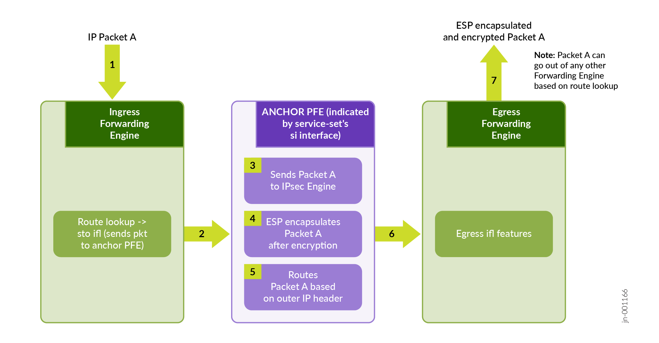
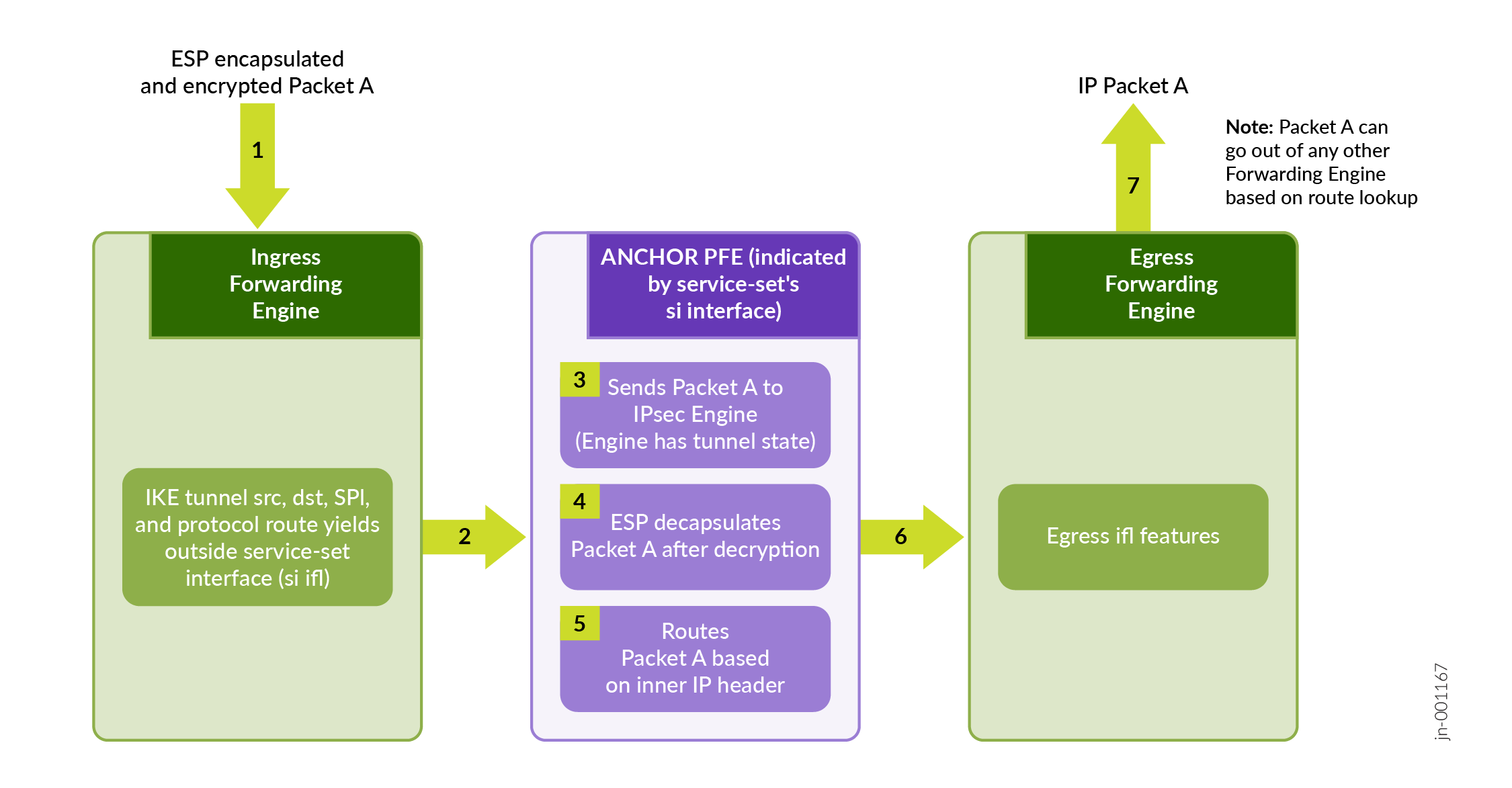
Figure 6 illustrates a high level view of ESP encapsulated packet that enters the router through an incoming interface and undergoes decapsulation.
Inline IPsec Multipath Forwarding with UDP Encapsulation
- UDP Encapsulation of ESP Traffic
- Layer 3 VXLAN Traffic Encapsulation using Flexible Tunnel Interfaces (FTIs)
UDP Encapsulation of ESP Traffic
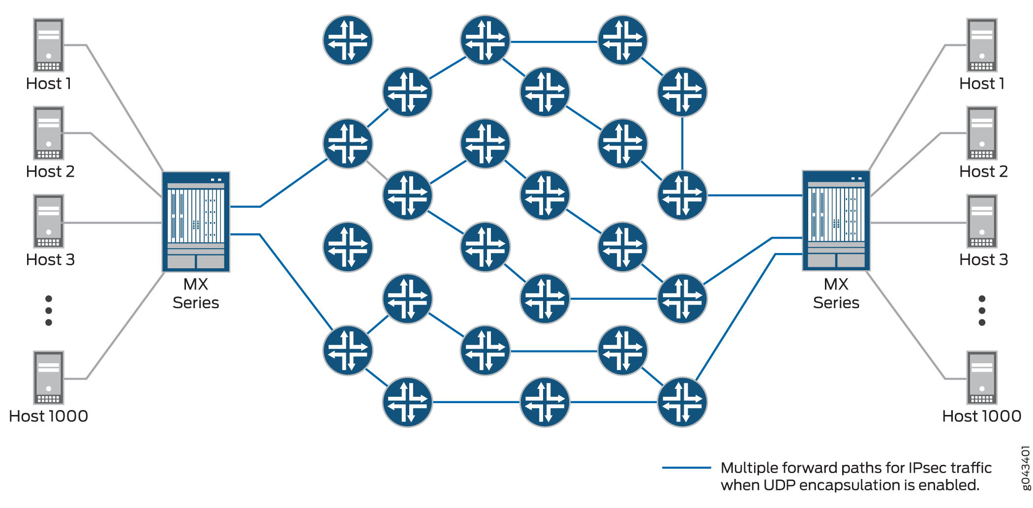
IPsec provides secure tunnels between two peers, and IPsec encapsulated packets have IP headers that contain tunnel endpoint IPs that do not change. This results in the selection of a single forwarding path between the peers, as shown in Figure 7. When IPsec traffic is flowing between data centers with thousands of hosts, this single path selection limits the throughput.
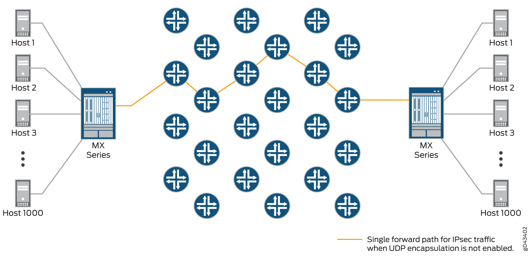
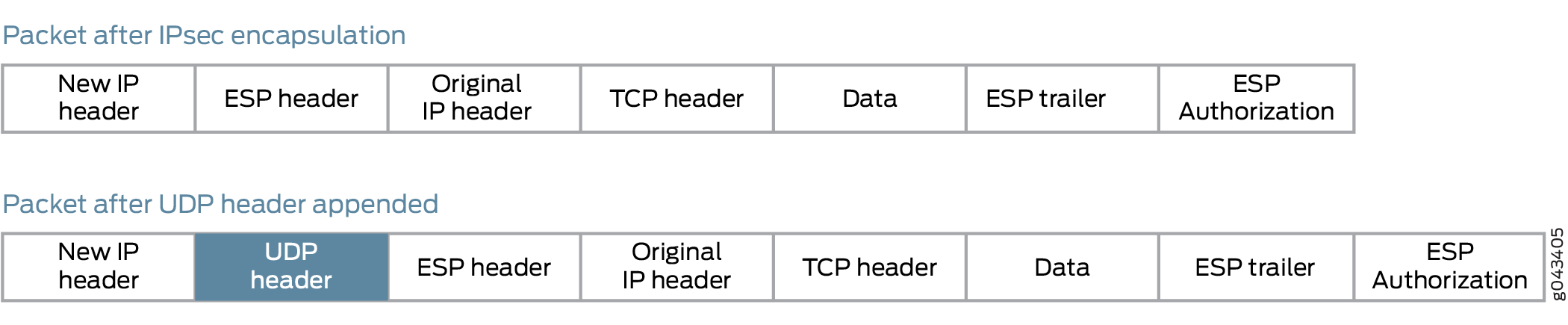
You can overcome this problem by enabling UDP encapsulation of the IPsec packets, which appends a UDP header after the ESP header, as shown in Figure 8 .This provides Layer 3 and 4 information to the intermediate routers, and the IPsec packets are forwarded over multiple paths, as shown in Figure 9 . You enable UDP encapsulation for the service set.
You can configure the UDP destination port with the value ranging from 1025 through 65536. The default destination port number is 500. You cannot configure 4500 as the destination port because it is a well-known port for NAT traversals.
The generated source port value is from 49152 through 65535.
UDP encapsulation supports Network Address Translation-Traversal (NAT-T)
Detection of a NAT device between IPsec peers takes precedence over UDP encapsulation configuration. If UDP encapsulation is configured between two peers, but NAT is detected between the same peers, NAT-Traversal mechanisms are implemented.
An Inbound IP packet is dropped if:
-
udp-encapsulationis enabled and if the received IP packet does not have UDP header. -
udp-encapsulationis enabled and if the UDP destination port is not same as configured. -
udp-encapsulationis enabled and if the UDP destination port is not 500 or not configured.
To enable or disable UDP encapsulation and to configure UDP destination port:
Configure the global non-standard destination port. This is required to register or open-up the port for IPsec. You cannot assign port 500 and port 4500 as they bound to IPsec, by default.
[edit security ike]
user@host> set packet-encapsulation dest-port dest-port
Enable packet encapsulation in IKE gateway.
[edit security ike  gateway gw1]
user@host> set packet-encapsulation
Configure the UDP destination port to non-standard port.
[edit security ike  gateway gw1]
user@host> set packet-encapsulation use-global-dest-port
Layer 3 VXLAN Traffic Encapsulation using Flexible Tunnel Interfaces (FTIs)
Junos OS supports VXLAN traffic over an IPsec tunnel using both FTIs and VTEP VXLANs. For more information see, Configuring Flexible Tunnel Interfaces and Understanding VXLANS.
Supported IPsec and IKE Standards for Inline IPsec
The following RFCs provide information about IPsec, IKE, and related technologies:
-
RFC 2085, HMAC-MD5 IP Authentication with Replay Prevention
-
RFC 2401, Security Architecture for the Internet Protocol (obsoleted by RFC 4301)
-
RFC 2402, IP Authentication Header (obsoleted by RFC 4302)
-
RFC 2403 The Use of HMAC-MD5-96 within ESP and AH
-
RFC 2404 The Use of HMAC-SHA-1-96 within ESP and AH (obsoleted by RFC 4305)
-
RFC 2405 The ESP DES-CBC Cipher Algorithm With Explicit IV
-
RFC 2406 IP Encapsulating Security Payload (ESP) (obsoleted by RFC 4303 and RFC 4305)
-
RFC 2407 The Internet IP Security Domain of Interpretation for ISAKMP (obsoleted by RFC 4306)
-
RFC 2408 Internet Security Association and Key Management Protocol (ISAKMP) (obsoleted by RFC 4306)
-
RFC 2409 The Internet Key Exchange (IKE) (obsoleted by RFC 4306)
-
RFC 2410 The NULL Encryption Algorithm and Its Use With IPsec
-
RFC 2451 The ESP CBC-Mode Cipher Algorithms
-
RFC 2560 X.509 Internet Public Key Infrastructure Online Certificate Status Protocol - OCSP
-
RFC 3193 Securing L2TP using IPsec
-
RFC 3280 Internet X.509 Public Key Infrastructure Certificate and Certificate Revocation List (CRL) Profile
-
RFC 3602 The AES-CBC Cipher Algorithm and Its Use with IPsec
-
RFC 3948 UDP Encapsulation of IPsec ESP Packets
-
RFC 4106 The Use of Galois/Counter Mode (GCM) in IPsec Encapsulating Security Payload (ESP)
-
RFC 4210 Internet X.509 Public Key Infrastructure Certificate Management Protocol (CMP)
-
RFC 4211, Internet X.509 Public Key Infrastructure Certificate Request Message Format (CRMF)
-
RFC 4301, Security Architecture for the Internet Protocol
-
RFC 4302, IP Authentication Header
-
RFC 4303, IP Encapsulating Security Payload (ESP)
-
RFC 4305, Cryptographic Algorithm Implementation Requirements for Encapsulating Security Payload (ESP) and Authentication Header (AH)
-
RFC 4306, Internet Key Exchange (IKEv2) Protocol
-
RFC 4307, Cryptographic Algorithms for Use in the Internet Key Exchange Version 2 (IKEv2)
-
RFC 4308, Cryptographic Suites for IPsec
Only Suite VPN-A is supported in Junos OS.
-
RFC 4754, IKE and IKEv2 Authentication Using the Elliptic Curve Digital Signature Algorithm (ECDSA)
-
RFC 4835, Cryptographic Algorithm Implementation Requirements for Encapsulating Security Payload (ESP) and Authentication Header (AH)
-
RFC 5996, Internet Key Exchange Protocol Version 2 (IKEv2) (obsoleted by RFC 7296)
-
RFC 7296, Internet Key Exchange Protocol Version 2 (IKEv2)
-
RFC 7427, Signature Authentication in the Internet Key Exchange Version 2 (IKEv2)
-
RFC 7634, ChaCha20, Poly1305, and Their Use in the Internet Key Exchange Protocol (IKE) and IPsec
-
RFC 8200, Internet Protocol, Version 6 (IPv6) Specification
Junos OS partially supports the following RFCs for IPsec and IKE:
-
RFC 3526, More Modular Exponential (MODP) Diffie-Hellman groups for Internet Key Exchange (IKE)
-
RFC 5114, Additional Diffie-Hellman Groups for Use with IETF Standards
-
RFC 5903, Elliptic Curve Groups modulo a Prime (ECP Groups) for IKE and IKEv2
The following RFCs and Internet draft do not define standards, but provide information about IPsec, IKE, and related technologies. The IETF classifies them as “Informational.”
-
RFC 2104, HMAC: Keyed-Hashing for Message Authentication
-
RFC 2412, The OAKLEY Key Determination Protocol
-
RFC 3706, A Traffic-Based Method of Detecting Dead Internet Key Exchange (IKE) Peers
-
Internet draft draft-eastlake-sha2-02.txt, US Secure Hash Algorithms (SHA and HMAC-SHA) (expires July 2006)
See Also
Inline IPsec with Traffic Selector Support
Integrating traffic selectors within inline IPsec deployments provides nuanced control over VPN traffic management. Defining traffic selectors set criteria for local and remote IP addresses that can traverse the IPsec tunnel, creating rules that dictate traffic flow.
Traffic Selector for Inline IPsec
Overview
Inline IPsec allows you to achieve encryption and decryption directly within the Packet Forwarding Engine, enhancing security and efficiency by eliminating the need for a dedicated services card. Traffic Selector style configurations allow for the creation of multiple Phase 2 IPsec security associations with distinct traffic parameters, offering granular security management and enforcing strict adherence to the security policy. Traffic Selector facilitates granular control over IPsec tunnel traffic by enabling filtering based on configured and negotiated local and remote address pairs.
In MX-SPC3 implementations, the traffic-selector is managed by the services card. However, with inline IPsec, the MX-Packet Forwarding Engine takes over the role of applying the traffic-selector. A traffic selector is an agreement between IKE peers to permit traffic through a tunnel if the traffic matches a specified pair of local and remote addresses. Other parameters like source port, remote port, and protocol can also be used for traffic selection. Essentially, a traffic-selector acts like a filter created by IKE and applied by the PFE. Depending on the configuration, this filter (or set of filters) functions in two main scenarios:
Traffic flowing towards the tunnel-If the incoming plain text IP packet satisfies the traffic selector, the packet is forwarded towards the IPSec tunnel for ESP processing.
Traffic incoming on to the tunnel-Once the packet has undergone ESP processing, the plain text IP packet is forwarded out, if it satisfies the traffic selector
The system supports secure tunnel mode and ESP protocols, essential for robust security standards, while transport mode and Authentication Header (AH) are excluded due to control plane limitations.
Configuration and Compatibility
Traffic Selector for inline IPsec supports ESP tunnel mode ensuring robust security for
your network communications. To configure a traffic selector, use the
traffic-selector configuration statement at the [edit security
ipsec vpn vpn-name] hierarchy level. The traffic selector is
defined with the mandatory local-ip ip-address/netmask
and remote-ip ip-address/netmask statements. For more
information, see traffic-selector.
The CLI operational command show security ipsec security-association
detail displays traffic selector information for SAs. The show security
ipsec security-association traffic-selector
traffic-selector-name CLI command displays information for a
specified traffic selector.
For a given traffic selector, a single address and netmask is specified for the local and remote addresses. Traffic selectors can be configured with IPv4 or IPv6 addresses.
Multiple traffic selectors can be configured for the same VPN. A maximum of 200 traffic selectors can be configured for each VPN. Traffic selectors can be used with IPv4-in-IPv4, IPv4-in-IPv6, IPv6-in-IPv6, or IPv6-in-IPv4 tunnel modes.
The following features are not supported with traffic selectors:
-
Different address families configured for the local and remote IP addresses in the same traffic selector
-
A remote address of 0.0.0.0/0 (IPv4) or 0::0 (IPv6) for site-to-site VPNs
-
Dynamic routing protocols configured on st0 interfaces
You can configure multiple sets of local IP prefix, remote IP prefix, source port range, destination port range, and protocol for traffic selection. This means, multiple sets of IP address ranges, port ranges, and protocols can be part of same traffic selector as defined in RFC 7296. When you configure multiple traffic selectors, each traffic selector leads to a separate negotiation that results in the multiple IPsec tunnels. But, if you configure multiple terms under one traffic selector, this configuration results in single IPsec SA negotiation with multiple IP prefixes, ports, and protocols.
Understanding Auto Route Insertion
Auto route insertion (ARI) automatically inserts a static route for the remote network and hosts protected by a remote tunnel endpoint. A route is created based on the remote IP address configured in the traffic-selector. In the case of traffic selectors, the configured remote address is inserted as a route in the routing instance associated with the st0 interface that is bound to the VPN.
Routing protocols and traffic selector configuration are mutually exclusive ways of steering traffic to a tunnel. ARI routes might conflict with routes that are populated through routing protocols. Therefore, you should not configure routing protocols on an st0 interface that is bound to a VPN on which traffic selectors are configured.
ARI is also known as reverse route insertion (RRI). ARI routes are inserted in the routing table as follows:
-
If the
establish-tunnels immediatelyoption is configured at the [edit security ipsec vpn vpn-name] hierarchy level, ARI routes are added after Phase 1 and Phase 2 negotiations are complete. Because a route is not added until SAs are established, a failed negotiation does not result in traffic being routed to a st0 interface that is down. An alternate or backup tunnel is used instead. -
If the
establish-tunnels immediatelyoption is not configured at the [edit security ipsec vpn vpn-name] hierarchy level, ARI routes are added at configuration commit. -
An ARI route is not added if the configured or negotiated remote address in a traffic selector is 0.0.0.0/0 or 0::0.
The preference for the static ARI route is 5. This value is necessary to avoid conflict with similar routes that might be added by a routing protocol process.
The static ARI route cannot be leaked to other routing instances using the
rib-groups configuration. Use the import-policy
configuration to leak static ARI routes.
- Overlapping IP Addresses in the Same VPN Bound to the Same st0 Interface
- Overlapping IP Addresses in Different VPNs Bound to Different st0 Interfaces
Overlapping IP Addresses in the Same VPN Bound to the Same st0 Interface
When overlapping IP addresses are configured for multiple traffic selectors in the same VPN, the first configured traffic selector that matches the packet determines the tunnel used for packet encryption.
In the following example, four traffic selectors (ts-1, ts-2, ts-3, and ts-4) are configured for the VPN (vpn-1), which is bound to the point-to-point st0.1 interface:
[edit]
user@host# show security ipsec vpn vpn-1
vpn vpn-1 {
bind-interface st0.1;
traffic-selector ts-1 {
local-ip 192.168.5.0/24;
remote-ip 10.1.5.0/24;
}
traffic-selector ts-2 {
local-ip 192.168.0.0/16;
remote-ip 10.1.0.0/16;
}
traffic-selector ts-3 {
local-ip 172.16.0.0/16;
remote-ip 10.2.0.0/16;
}
traffic-selector ts-4 {
local-ip 172.16.5.0/24;
remote-ip 10.2.5.0/24;
}
}
A packet with a source address 192.168.5.5 and a destination address 10.1.5.10 matches traffic selectors ts-1 and ts-2. However, traffic selector ts-1 is the first configured match and the tunnel associated with ts-1 is used for packet encryption.
A packet with a source address 172.16.5.5 and a destination address 10.2.5.10 matches the traffic selectors ts-3 and ts-4. However, traffic selector ts-3 is the first configured match and the tunnel associated with traffic selector ts-3 is used for packet encryption.
Overlapping IP Addresses in Different VPNs Bound to Different st0 Interfaces
When overlapping IP addresses are configured for multiple traffic selectors in different VPNs that are bound to different point-to-point st0 interfaces, an st0 interface is first selected by the longest prefix match for a given packet. Within the VPN that is bound to the selected st0 interface, the traffic selector is then selected based on the first configured match for the packet.
In the following example, a traffic selector is configured in each of two VPNs. The traffic selectors are configured with the same local subnetwork but different remote subnetworks.
[edit]
user@host# show security ipsec
vpn vpn-1 {
    bind-interface st0.1;
    traffic-selector ts-1 {
        local-ip 192.168.1.0/24;
        remote-ip 10.1.1.0/24;
    }
}
vpn vpn-2 {
    bind-interface st0.2;
    traffic-selector ts-2 {
        local-ip 192.168.1.0/24;
        remote-ip 10.2.2.0/24;
    }
}
Different remote subnetworks are configured in each traffic selector, therefore two different routes are added to the routing table. Route lookup uses the st0 interface bound to the appropriate VPN.
In the following example, a traffic selector is configured in each of two VPNs. The traffic selectors are configured with different remote subnetworks. The same local subnetwork is configured for each traffic selector, but different netmask values are specified.
[edit]
user@host# show security ipsec
vpn vpn-1 {
    bind-interface st0.1;
    traffic-selector ts-1 {
        local-ip 192.168.0.0/8;
        remote-ip 10.1.1.0/24;
    }
}
vpn vpn-2 {
    bind-interface st0.2;
    traffic-selector ts-2 {
        local-ip 192.168.0.0/16;
        remote-ip 10.2.2.0/24;
    }
}
A different remote subnetwork is configured in each traffic selector, therefore two different routes are added to the routing table. Route lookup uses the st0 interface bound to the appropriate VPN.
In the following example, traffic selectors are configured in each of two VPNs. The traffic selectors are configured with different local and remote subnetworks.
[edit]
user@host# show security ipsec
vpn vpn-1 {
    bind-interface st0.1;
    traffic-selector ts-1 {
        local-ip 192.168.1.0/24;
        remote-ip 10.1.1.0/24;
    }
}
vpn vpn-2 {
    bind-interface st0.2;
    traffic-selector ts-2 {
        local-ip 172.16.1.0/24;
        remote-ip 10.2.2.0/24;
    }
}
In this case, the traffic selectors do not overlap. The remote subnetworks configured in the traffic selectors are different, therefore two different routes are added to the routing table. Route lookup uses the st0 interface bound to the appropriate VPN.
In the following example, a traffic selector is configured in each of two VPNs. The traffic selectors are configured with the same local subnetwork. The same remote subnetwork is configured for each traffic selector, but different netmask values are specified.
[edit]
user@host# show security ipsec
vpn vpn-1 {
    bind-interface st0.1;
    traffic-selector ts-1 {
        local-ip 192.168.1.0/24;
        remote-ip 10.1.1.0/24;
    }
}
vpn vpn-2 {
    bind-interface st0.2;
    traffic-selector ts-2 {
        local-ip 192.168.1.0/24;
        remote-ip 10.1.0.0/16;
    }
}
Note that the remote-ip configured for ts-1 is 10.1.1.0/24 while the
remote-ip configured for ts-2 is 10.1.0.0/16. For a packet destined
to 10.1.1.1, route lookup selects the st0.1 interface as it has the longer prefix match.
The packet is encrypted based on the tunnel corresponding to the st0.1 interface.
In some cases, valid packets can be dropped due to traffic selector traffic enforcement. In the following example, traffic selectors are configured in each of two VPNs. The traffic selectors are configured with different local subnetworks. The same remote subnetwork is configured for each traffic selector, but different netmask values are specified.
[edit]
user@host# show security ipsec
vpn vpn-1 {
    bind-interface st0.1;
    traffic-selector ts-1 {
        local-ip 192.168.1.0/24;
        remote-ip 10.1.1.0/24;
    }
}
vpn vpn-2 {
    bind-interface st0.2;
    traffic-selector ts-2 {
        local-ip 172.16.1.0/16;
        remote-ip 10.1.0.0/16;
    }
}
Two routes to 10.1.1.0 (10.1.1.0/24 via interface st0.1 and 10.1.0.0/16 via interface st0.2) are added to the routing table. A packet sent from source 172.16.1.1 to destination 10.1.1.1 matches the routing table entry for 10.1.1.0/24 via interface st0.1. However, the packet does not match the traffic specified by traffic selector ts-1 and is dropped.
If multiple traffic selectors are configured with the same remote subnetwork and netmask, equal cost routes are added to the routing table. This case is not supported with traffic selectors as the route chosen cannot be predicted.
Example: Configuring Traffic Selectors in a Route-Based Inline IPSec VPN
This example shows how to configure traffic selectors for a route-based VPN.
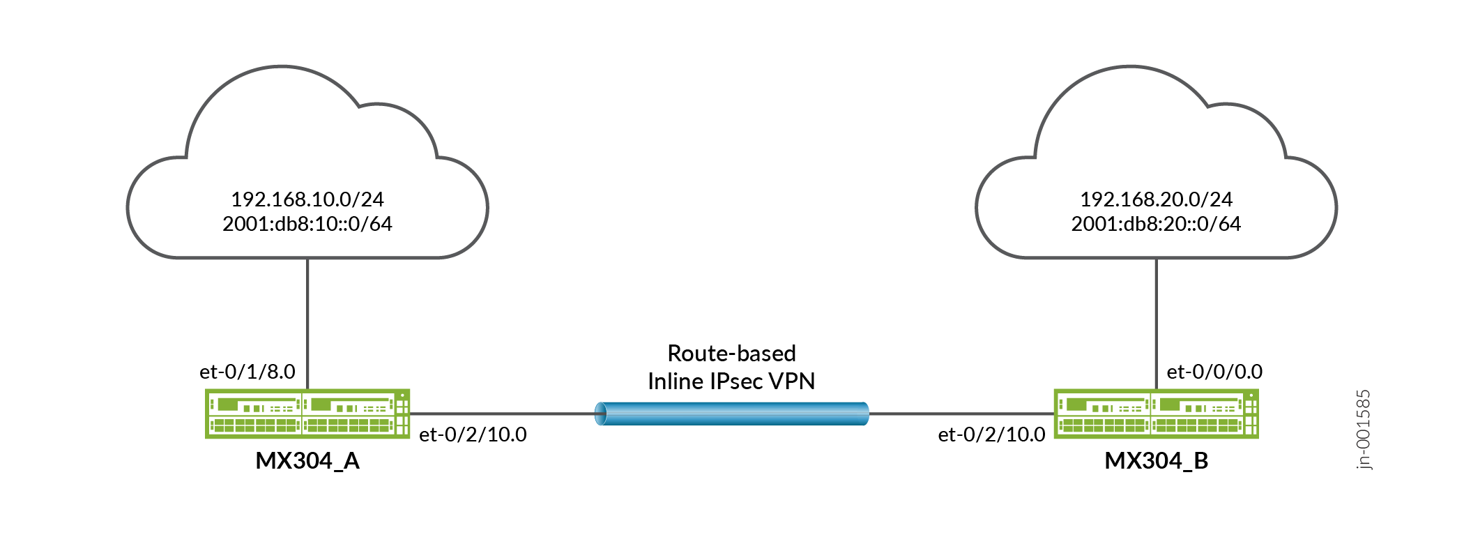
Overview
This example configures traffic selectors to allow traffic to flow between subnetworks on MX304_A and subnetworks on MX304_B.
Table 8 shows the traffic selectors for this example.
MX304_A |
MX304_B |
||||
|---|---|---|---|---|---|
Traffic Selector Name |
Local IP |
Remote IP |
Traffic Selector Name |
Local IP |
Remote IP |
ts1-ipv4 |
192.168.10.0/24 |
192.168.0.0/16 |
ts1-ipv4 |
192.168.0.0/16 |
192.168.10.0/24 |
ts2-ipv6 |
2001:db8:10::0/64 |
2001:db8:20::0/64 |
ts2-ipv6 |
2001:db8:20::0/64 |
2001:db8:10::0/64 |
Topology
In Figure 10, an IPv4 VPN tunnel carries IPv4 traffic and an IPv6 VPN tunnel carries IPv6 traffic between the MX304_A and MX304_B devices. That is, one tunnel operates in IPv4-in-IPv4 tunnel mode while the other tunnel operates in IPv6-in-IPv6 tunnel mode.
Configuration
Configuring MX304_A
CLI Quick Configuration
To quickly configure this example, copy the following commands, paste them into a text file, remove any line breaks, change any details necessary to match your network configuration, copy and paste the commands into the CLI at the [edit] hierarchy level, and then enter commit from configuration mode.
set chassis fpc 0 pic 1 inline-services bandwidth 10g
set services service-set ssv4_ts1 next-hop-service inside-service-interface si-0/1/0.1
set services service-set ssv4_ts1 next-hop-service outside-service-interface si-0/1/0.2
set services service-set ssv4_ts1 ipsec-vpn ipsec_vpnv4_ts1
set services service-set ssv6_ts1 next-hop-service inside-service-interface si-0/1/0.3
set services service-set ssv6_ts1 next-hop-service outside-service-interface si-0/1/0.4
set services service-set ssv6_ts1 ipsec-vpn ipsec_vpnv6_ts1
set security ike proposal ike_prop description "IKE Proposal"
set security ike proposal ike_prop authentication-method pre-shared-keys
set security ike proposal ike_prop lifetime-seconds 300
set security ike policy ike_policy mode main
set security ike policy ike_policy proposals ike_prop
set security ike policy ike_policy pre-shared-key ascii-text test123
set security ike gateway ike_gw ike-policy ike_policy
set security ike gateway ike_gw address 10.1.1.2
set security ike gateway ike_gw external-interface et-0/2/10
set security ike gateway ike_gw local-address 10.1.1.1
set security ike gateway ike_gw version v2-only
set security ike gateway ike_gwv6 ike-policy ike_policy
set security ike gateway ike_gwv6 address 2001:db8:1611::2
set security ike gateway ike_gwv6 external-interface et-0/2/10
set security ike gateway ike_gwv6 local-address 2001:db8:1611::1
set security ike gateway ike_gwv6 version v2-only
set security ipsec vpn ipsec_vpnv4_ts1 bind-interface st0.1
set security ipsec vpn ipsec_vpnv4_ts1 ike gateway ike_gw
set security ipsec vpn ipsec_vpnv4_ts1 ike ipsec-policy ipsec_policy
set security ipsec vpn ipsec_vpnv4_ts1 ike install-interval 3
set security ipsec vpn ipsec_vpnv4_ts1 traffic-selector ts1-ipv4 term 0 local-ip 192.168.10.0/24
set security ipsec vpn ipsec_vpnv4_ts1 traffic-selector ts1-ipv4 term 0 remote-ip 192.168.20.0/24
set security ipsec vpn ipsec_vpnv4_ts1 traffic-selector ts1-ipv4 term 0 protocol tcp
set security ipsec vpn ipsec_vpnv4_ts1 traffic-selector ts1-ipv4 term 0 source-port 500-1010
set security ipsec vpn ipsec_vpnv4_ts1 traffic-selector ts1-ipv4 term 0 destination-port 500-1010
set security ipsec vpn ipsec_vpnv4_ts1 establish-tunnels immediately
set security ipsec vpn ipsec_vpnv6_ts1 bind-interface st0.2
set security ipsec vpn ipsec_vpnv6_ts1 ike gateway ike_gwv6
set security ipsec vpn ipsec_vpnv6_ts1 ike ipsec-policy ipsec_policy
set security ipsec vpn ipsec_vpnv6_ts1 ike install-interval 3
set security ipsec vpn ipsec_vpnv6_ts1 traffic-selector ts1-ipv6 term 1 local-ip 2001:db8:10::/64
set security ipsec vpn ipsec_vpnv6_ts1 traffic-selector ts1-ipv6 term 1 remote-ip 2001:db8:20::/64
set security ipsec vpn ipsec_vpnv6_ts1 traffic-selector ts1-ipv6 term 1 protocol tcp
set security ipsec vpn ipsec_vpnv6_ts1 traffic-selector ts1-ipv6 term 1 source-port 500-1010
set security ipsec vpn ipsec_vpnv6_ts1 traffic-selector ts1-ipv6 term 1 destination-port 500-1010
set security ipsec vpn ipsec_vpnv6_ts1 establish-tunnels immediately
set interfaces si-0/1/0 unit 1 family inet
set interfaces si-0/1/0 unit 1 family inet6
set interfaces si-0/1/0 unit 1 service-domain inside
set interfaces si-0/1/0 unit 2 family inet
set interfaces si-0/1/0 unit 2 family inet6
set interfaces si-0/1/0 unit 2 service-domain outside
set interfaces si-0/1/0 unit 3 family inet
set interfaces si-0/1/0 unit 3 family inet6
set interfaces si-0/1/0 unit 3 service-domain inside
set interfaces si-0/1/0 unit 4 family inet
set interfaces si-0/1/0 unit 4 family inet6
set interfaces si-0/1/0 unit 4 service-domain outside
set interfaces et-0/1/8 unit 0 family inet address 172.16.2.1/24
set interfaces et-0/1/8 unit 0 family inet6 address 2001:db8:2000::1/64
set interfaces et-0/2/10 unit 0 family inet address 10.1.1.1/24
set interfaces et-0/2/10 unit 0 family inet6 address 2001:db8:2001:db8:1611::1/64
set interfaces st0 unit 1 family inet
set interfaces st0 unit 1 family inet6
set interfaces st0 unit 2 family inet
set interfaces st0 unit 2 family inet6
Step-by-Step Procedure
The following example requires you to navigate various levels in the configuration hierarchy. For instructions on how to do that, see Using the CLI Editor in Configuration Mode in the CLI User Guide.
To configure traffic selectors:
Configuring chassis to enable inline services.
[edit]
user@host# set chassis fpc 0 pic 1 inline-services bandwidth 10g
Configuring service sets for IPv4 VPN and IPv6 VPN objects.
[edit]
user@host# set services service-set ssv4_ts1 next-hop-service inside-service-interface si-0/1/0.1
user@host# set services service-set ssv4_ts1 next-hop-service outside-service-interface si-0/1/0.2
user@host# set services service-set ssv4_ts1 ipsec-vpn ipsec_vpnv4_ts1
user@host# set services service-set ssv6_ts1 next-hop-service inside-service-interface si-0/1/0.3
user@host# set services service-set ssv6_ts1 next-hop-service outside-service-interface si-0/1/0.4
user@host# set services service-set ssv6_ts1 ipsec-vpn ipsec_vpnv6_ts1
Configure IKE proposal.
[edit]
user@host# set security ike proposal ike_prop description "IKE Proposal"
user@host# set security ike proposal ike_prop authentication-method pre-shared-keys
user@host# set security ike proposal ike_prop lifetime-seconds 300
user@host# set security ike policy ike_policy mode main
user@host# set security ike policy ike_policy proposals ike_prop
user@host# set security ike policy ike_policy pre-shared-key ascii-text test123
Configure IKE policy and IPv4 IKE gateway.
[edit]
user@host# set security ike gateway ike_gw ike-policy ike_policy
user@host# set security ike gateway ike_gw address 10.1.1.2
user@host# set security ike gateway ike_gw external-interface et-0/2/10
user@host# set security ike gateway ike_gw local-address 10.1.1.1
user@host# set security ike gateway ike_gw version v2-only
Configure IKE policy and IPv6 IKE gateway.
[edit]
user@host# set security ike gateway ike_gwv6 ike-policy ike_policy
user@host# set security ike gateway ike_gwv6 address 2001:db8:1611::2
user@host# set security ike gateway ike_gwv6 external-interface et-0/2/10
user@host# set security ike gateway ike_gwv6 local-address 2001:db8:1611::1
user@host# set security ike gateway ike_gwv6 version v2-only
Configure IPsec proposal.
[edit]
user@host# set security ipsec proposal ipsec_prop description "IPSec Proposal"
user@host# set security ipsec proposal ipsec_prop protocol esp
user@host# set security ipsec proposal ipsec_prop encryption-algorithm aes-256-gcm
user@host# set security ipsec proposal ipsec_prop lifetime-seconds 180
Configure IPsec policy.
[edit]
user@host# set security ipsec policy ipsec_policy proposals ipsec_prop
Configure IPv4 IPsec VPN tunnel.
[edit]
user@host# set security ipsec vpn ipsec_vpnv4_ts1 bind-interface st0.1
user@host# set security ipsec vpn ipsec_vpnv4_ts1 ike gateway ike_gw
user@host# set security ipsec vpn ipsec_vpnv4_ts1 ike ipsec-policy ipsec_policy
user@host# set security ipsec vpn ipsec_vpnv4_ts1 ike install-interval 3
user@host# set security ipsec vpn ipsec_vpnv4_ts1 traffic-selector ts1-ipv4 term 0 local-ip 192.168.10.0/24
user@host# set security ipsec vpn ipsec_vpnv4_ts1 traffic-selector ts1-ipv4 term 0 remote-ip 192.168.20.0/24
user@host# set security ipsec vpn ipsec_vpnv4_ts1 traffic-selector ts1-ipv4 term 0 protocol tcp
user@host# set security ipsec vpn ipsec_vpnv4_ts1 traffic-selector ts1-ipv4 term 0 source-port 500-1010
user@host# set security ipsec vpn ipsec_vpnv4_ts1 traffic-selector ts1-ipv4 term 0 destination-port 500-1010
user@host# set security ipsec vpn ipsec_vpnv4_ts1 establish-tunnels immediately
Configure IPv6 IPsec VPN tunnel.
[edit]
user@host# set security ipsec vpn ipsec_vpnv6_ts1 bind-interface st0.2
user@host# set security ipsec vpn ipsec_vpnv6_ts1 ike gateway ike_gwv6
user@host# set security ipsec vpn ipsec_vpnv6_ts1 ike ipsec-policy ipsec_policy
user@host# set security ipsec vpn ipsec_vpnv6_ts1 ike install-interval 3
user@host# set security ipsec vpn ipsec_vpnv6_ts1 traffic-selector ts1-ipv6 term 1 local-ip 2001:db8:10::/64
user@host# set security ipsec vpn ipsec_vpnv6_ts1 traffic-selector ts1-ipv6 term 1 remote-ip 2001:db8:20::/64
user@host# set security ipsec vpn ipsec_vpnv6_ts1 traffic-selector ts1-ipv6 term 1 protocol tcp
user@host# set security ipsec vpn ipsec_vpnv6_ts1 traffic-selector ts1-ipv6 term 1 source-port 500-1010
user@host# set security ipsec vpn ipsec_vpnv6_ts1 traffic-selector ts1-ipv6 term 1 destination-port 500-1010
user@host# set security ipsec vpn ipsec_vpnv6_ts1 establish-tunnels immediately
Configuring inline service interfaces
[edit]
user@host# set interfaces si-0/1/0 unit 1 family inet
user@host# set interfaces si-0/1/0 unit 1 family inet6
user@host# set interfaces si-0/1/0 unit 1 service-domain inside
user@host# set interfaces si-0/1/0 unit 2 family inet
user@host# set interfaces si-0/1/0 unit 2 family inet6
user@host# set interfaces si-0/1/0 unit 2 service-domain outside
user@host# set interfaces si-0/1/0 unit 3 family inet
user@host# set interfaces si-0/1/0 unit 3 family inet6
user@host# set interfaces si-0/1/0 unit 3 service-domain inside
user@host# set interfaces si-0/1/0 unit 4 family inet
user@host# set interfaces si-0/1/0 unit 4 family inet6
user@host# set interfaces si-0/1/0 unit 4 service-domain outside
Configure the interfaces.
[edit]
user@host# set interfaces et-0/1/8 unit 0 family inet address 172.16.2.1/24
user@host# set interfaces et-0/1/8 unit 0 family inet6 address 2001:db8:2000::1/64
user@host# set interfaces et-0/2/10 unit 0 family inet address 10.1.1.1/24
user@host# set interfaces et-0/2/10 unit 0 family inet6 address 2001:db8:2001:db8:1611::1/64
user@host# set interfaces st0 unit 1 family inet
user@host# set interfaces st0 unit 1 family inet6
user@host# set interfaces st0 unit 2 family inet
user@host# set interfaces st0 unit 2 family inet6
Results
From configuration mode, confirm your configuration by entering the show interfaces, show security ike, and show security ipsec commands. If the output does not display the intended configuration, repeat the configuration instructions in this example to correct it.
[edit]
    user@host# show interfaces
    si-0/1/0 {
        unit 1 {
            family inet;
            family inet6;
            service-domain inside;
        }
        unit 2 {
            family inet;
            family inet6;
            service-domain outside;
        }
        unit 3 {
            family inet;
            family inet6;
            service-domain inside;
        }
        unit 4 {
            family inet;
            family inet6;
            service-domain outside;
        }
    }
    et-0/1/8 {
        unit 0 {
            family inet {
                address 172.16.2.1/24;
            }
            family inet6 {
                address 2001:db8:2000::1/64;
            }
        }
    }
    et-0/2/10 {
        unit 0 {
            family inet {
                address 10.1.1.1/24;
            }
            family inet6 {
                address 2001:db8:2001:db8:1611::1/64;
            }
        }
    }
    st0 {
        unit 1 {
            family inet;
            family inet6;
        }
        unit 2 {
            family inet;
            family inet6;
        }
    }
}

    [edit]
    user@host# show security ike
          proposal ike_prop {
            description "IKE Proposal";
            authentication-method pre-shared-keys;
            lifetime-seconds 300;
        }
        policy ike_policy {
            mode main;
            proposals ike_prop;
            pre-shared-key ascii-text "$9$skYJD.mT3/t5Q"; ## SECRET-DATA
        }
        gateway ike_gw {
            ike-policy ike_policy;
            address 10.1.1.2;
            external-interface et-0/2/10;
            local-address 10.1.1.1;
            version v2-only;
        }
        gateway ike_gwv6 {
            ike-policy ike_policy;
            address 2001:db8:1611::2;
            external-interface et-0/2/10;
            local-address 2001:db8:1611::1;
            version v2-only;
        }
    }


    [edit]
    user@host# show security ipsec
    ipsec {
        proposal ipsec_prop {
            description "IPSec Proposal";
            protocol esp;
            encryption-algorithm aes-256-gcm;
            lifetime-seconds 180;
        }
        policy ipsec_policy {
            proposals ipsec_prop;
        }
        vpn ipsec_vpnv4_ts1 {
            bind-interface st0.1;
            ike {
                gateway ike_gw;
                ipsec-policy ipsec_policy;
                install-interval 3;
            }
            traffic-selector ts1-ipv4 {
                term 0 {
                    local-ip 192.168.10.0/24;
                    remote-ip 192.168.20.0/24;
                    protocol tcp;
                    source-port 500-1010;
                    destination-port 500-1010;
                }
            }
            establish-tunnels immediately;
        }
        vpn ipsec_vpnv6_ts1 {
            bind-interface st0.2;
            ike {
                gateway ike_gwv6;
                ipsec-policy ipsec_policy;
                install-interval 3;
            }
            traffic-selector ts1-ipv6 {
                term 1 {
                    local-ip 2001:db8:10::/64;
                    remote-ip 2001:db8:20::/64;
                    protocol tcp;
                    source-port 500-1010;
                    destination-port 500-1010;
                }
            }
            establish-tunnels immediately;
        }
If you are done configuring the device, enter commit from configuration mode.
Configuring MX304_B
CLI Quick Configuration
To quickly configure this example, copy the following commands, paste them into a text file, remove any line breaks, change any details necessary to match your network configuration, copy and paste the commands into the CLI at the [edit] hierarchy level, and then enter commit from configuration mode.
set chassis fpc 0 pic 1 inline-services bandwidth 10g
set services service-set ssv4_ts1 next-hop-service inside-service-interface si-0/1/0.1
set services service-set ssv4_ts1 next-hop-service outside-service-interface si-0/1/0.2
set services service-set ssv4_ts1 ipsec-vpn ipsec_vpnv4_ts1
set services service-set ssv6_ts1 next-hop-service inside-service-interface si-0/1/0.3
set services service-set ssv6_ts1 next-hop-service outside-service-interface si-0/1/0.4
set services service-set ssv6_ts1 ipsec-vpn ipsec_vpnv6_ts1
set security ike proposal ike_prop description "IKE Proposal"
set security ike proposal ike_prop authentication-method pre-shared-keys
set security ike proposal ike_prop lifetime-seconds 300
set security ike policy ike_policy mode main
set security ike policy ike_policy proposals ike_prop
set security ike policy ike_policy pre-shared-key ascii-text test123
set security ike gateway ike_gw ike-policy ike_policy
set security ike gateway ike_gw address 10.1.1.1
set security ike gateway ike_gw external-interface et-0/2/10
set security ike gateway ike_gw local-address 10.1.1.2
set security ike gateway ike_gw version v2-only
set security ike gateway ike_gwv6 ike-policy ike_policy
set security ike gateway ike_gwv6 address 2001:db8:1611::1
set security ike gateway ike_gwv6 external-interface et-0/2/10
set security ike gateway ike_gwv6 local-address 2001:db8:1611::2
set security ike gateway ike_gwv6 version v2-only
set security ipsec proposal ipsec_prop description "IPSec Proposal"
set security ipsec proposal ipsec_prop protocol esp
set security ipsec proposal ipsec_prop encryption-algorithm aes-256-gcm
set security ipsec proposal ipsec_prop lifetime-seconds 180
set security ipsec policy ipsec_policy proposals ipsec_prop
set security ipsec vpn ipsec_vpnv4_ts1 bind-interface st0.1
set security ipsec vpn ipsec_vpnv4_ts1 ike gateway ike_gw
set security ipsec vpn ipsec_vpnv4_ts1 ike ipsec-policy ipsec_policy
set security ipsec vpn ipsec_vpnv4_ts1 ike install-interval 3
set security ipsec vpn ipsec_vpnv4_ts1 traffic-selector ts1-ipv4 term 0 local-ip 192.168.20.0/24
set security ipsec vpn ipsec_vpnv4_ts1 traffic-selector ts1-ipv4 term 0 remote-ip 192.168.10.0/24
set security ipsec vpn ipsec_vpnv4_ts1 traffic-selector ts1-ipv4 term 0 protocol tcp
set security ipsec vpn ipsec_vpnv4_ts1 traffic-selector ts1-ipv4 term 0 source-port 500-1010
set security ipsec vpn ipsec_vpnv4_ts1 traffic-selector ts1-ipv4 term 0 destination-port 500-1010
set security ipsec vpn ipsec_vpnv4_ts1 establish-tunnels responder-only
set security ipsec vpn ipsec_vpnv6_ts1 bind-interface st0.2
set security ipsec vpn ipsec_vpnv6_ts1 ike gateway ike_gwv6
set security ipsec vpn ipsec_vpnv6_ts1 ike ipsec-policy ipsec_policy
set security ipsec vpn ipsec_vpnv6_ts1 ike install-interval 3
set security ipsec vpn ipsec_vpnv6_ts1 traffic-selector ts1-ipv6 term 1 local-ip 2001:db8:20::/64
set security ipsec vpn ipsec_vpnv6_ts1 traffic-selector ts1-ipv6 term 1 remote-ip 2001:db8:10::/64
set security ipsec vpn ipsec_vpnv6_ts1 traffic-selector ts1-ipv6 term 1 protocol tcp
set security ipsec vpn ipsec_vpnv6_ts1 traffic-selector ts1-ipv6 term 1 source-port 500-1010
set security ipsec vpn ipsec_vpnv6_ts1 traffic-selector ts1-ipv6 term 1 destination-port 500-1010
set security ipsec vpn ipsec_vpnv6_ts1 establish-tunnels responder-only
set interfaces si-0/1/0 unit 1 family inet
set interfaces si-0/1/0 unit 1 family inet6
set interfaces si-0/1/0 unit 1 service-domain inside
set interfaces si-0/1/0 unit 2 family inet
set interfaces si-0/1/0 unit 2 family inet6
set interfaces si-0/1/0 unit 2 service-domain outside
set interfaces si-0/1/0 unit 3 family inet
set interfaces si-0/1/0 unit 3 family inet6
set interfaces si-0/1/0 unit 3 service-domain inside
set interfaces si-0/1/0 unit 4 family inet
set interfaces si-0/1/0 unit 4 family inet6
set interfaces si-0/1/0 unit 4 service-domain outside
set interfaces et-0/0/0 unit 0 family inet address 172.16.1.1/24
set interfaces et-0/0/0 unit 0 family inet6 address 2001:db8:0:1::1/64
set interfaces et-0/2/10 unit 0 family inet address 10.1.1.2/24
set interfaces et-0/2/10 unit 0 family inet6 address 2001:db8:1611::2/64
set interfaces st0 unit 1 family inet
set interfaces st0 unit 1 family inet6
set interfaces st0 unit 2 family inet
set interfaces st0 unit 2 family inet6
Step-by-Step Procedure
The following example requires you to navigate various levels in the configuration hierarchy. For instructions on how to do that, see Using the CLI Editor in Configuration Mode in the CLI User Guide.
To configure traffic selectors:
Configuring chassis to enable inline services.
[edit]
user@host# set chassis fpc 0 pic 1 inline-services bandwidth 10g
Configuring service sets for IPv4 VPN and IPv6 VPN objects.
[edit]
user@host# set services service-set ssv4_ts1 next-hop-service inside-service-interface si-0/1/0.1
user@host# set services service-set ssv4_ts1 next-hop-service outside-service-interface si-0/1/0.2
user@host# set services service-set ssv4_ts1 ipsec-vpn ipsec_vpnv4_ts1
user@host# set services service-set ssv6_ts1 next-hop-service inside-service-interface si-0/1/0.3
user@host# set services service-set ssv6_ts1 next-hop-service outside-service-interface si-0/1/0.4
user@host# set services service-set ssv6_ts1 ipsec-vpn ipsec_vpnv6_ts1
Configure IKE proposal.
[edit]
user@host# set security ike proposal ike_prop description "IKE Proposal"
user@host# set security ike proposal ike_prop authentication-method pre-shared-keys
user@host# set security ike proposal ike_prop lifetime-seconds 300
user@host# set security ike policy ike_policy mode main
user@host# set security ike policy ike_policy proposals ike_prop
user@host# set security ike policy ike_policy pre-shared-key ascii-text test123
Configure IKE policy and IPv4 IKE gateway.
[edit]
user@host# set security ike gateway ike_gw ike-policy ike_policy
user@host# set security ike gateway ike_gw address 10.1.1.2
user@host# set security ike gateway ike_gw external-interface et-0/2/10
user@host# set security ike gateway ike_gw local-address 10.1.1.1
user@host# set security ike gateway ike_gw version v2-only
Configure IKE policy and IPv6 IKE gateway.
[edit]
user@host# set security ike gateway ike_gwv6 ike-policy ike_policy
user@host# set security ike gateway ike_gwv6 address 2001:db8:1611::2
user@host# set security ike gateway ike_gwv6 external-interface et-0/2/10
user@host# set security ike gateway ike_gwv6 local-address 2001:db8:1611::1
user@host# set security ike gateway ike_gwv6 version v2-only
Configure IPsec proposal.
[edit]
user@host# set security ipsec proposal ipsec_prop description "IPSec Proposal"
user@host# set security ipsec proposal ipsec_prop protocol esp
user@host# set security ipsec proposal ipsec_prop encryption-algorithm aes-256-gcm
user@host# set security ipsec proposal ipsec_prop lifetime-seconds 180
Configure IPsec policy.
[edit]
user@host# set security ipsec policy ipsec_policy proposals ipsec_prop
Configure IPv4 IPsec VPN tunnel.
[edit]
user@host# set security ipsec vpn ipsec_vpnv4_ts1 bind-interface st0.1
user@host# set security ipsec vpn ipsec_vpnv4_ts1 ike gateway ike_gw
user@host# set security ipsec vpn ipsec_vpnv4_ts1 ike ipsec-policy ipsec_policy
user@host# set security ipsec vpn ipsec_vpnv4_ts1 ike install-interval 3
user@host# set security ipsec vpn ipsec_vpnv4_ts1 traffic-selector ts1-ipv4 term 0 local-ip 192.168.10.0/24
user@host# set security ipsec vpn ipsec_vpnv4_ts1 traffic-selector ts1-ipv4 term 0 remote-ip 192.168.20.0/24
user@host# set security ipsec vpn ipsec_vpnv4_ts1 traffic-selector ts1-ipv4 term 0 protocol tcp
user@host# set security ipsec vpn ipsec_vpnv4_ts1 traffic-selector ts1-ipv4 term 0 source-port 500-1010
user@host# set security ipsec vpn ipsec_vpnv4_ts1 traffic-selector ts1-ipv4 term 0 destination-port 500-1010
user@host# set security ipsec vpn ipsec_vpnv4_ts1 establish-tunnels responder-only
Configure IPv6 IPsec VPN tunnel.
[edit security]
user@host# set security ipsec vpn ipsec_vpnv6_ts1 bind-interface st0.2
user@host# set security ipsec vpn ipsec_vpnv6_ts1 ike gateway ike_gwv6
user@host# set security ipsec vpn ipsec_vpnv6_ts1 ike ipsec-policy ipsec_policy
user@host# set security ipsec vpn ipsec_vpnv6_ts1 ike install-interval 3
user@host# set security ipsec vpn ipsec_vpnv6_ts1 traffic-selector ts1-ipv6 term 1 local-ip 2001:db8:10::/64
user@host# set security ipsec vpn ipsec_vpnv6_ts1 traffic-selector ts1-ipv6 term 1 remote-ip 2001:db8:20::/64
user@host# set security ipsec vpn ipsec_vpnv6_ts1 traffic-selector ts1-ipv6 term 1 protocol tcp
user@host# set security ipsec vpn ipsec_vpnv6_ts1 traffic-selector ts1-ipv6 term 1 source-port 500-1010
user@host# set security ipsec vpn ipsec_vpnv6_ts1 traffic-selector ts1-ipv6 term 1 destination-port 500-1010
user@host# set security ipsec vpn ipsec_vpnv6_ts1 establish-tunnels responder-only
Configuring inline service interfaces.
[edit]
user@host# set interfaces si-0/1/0 unit 1 family inet
user@host# set interfaces si-0/1/0 unit 1 family inet6
user@host# set interfaces si-0/1/0 unit 1 service-domain inside
user@host# set interfaces si-0/1/0 unit 2 family inet
user@host# set interfaces si-0/1/0 unit 2 family inet6
user@host# set interfaces si-0/1/0 unit 2 service-domain outside
user@host# set interfaces si-0/1/0 unit 3 family inet
user@host# set interfaces si-0/1/0 unit 3 family inet6
user@host# set interfaces si-0/1/0 unit 3 service-domain inside
user@host# set interfaces si-0/1/0 unit 4 family inet
user@host# set interfaces si-0/1/0 unit 4 family inet6
user@host# set interfaces si-0/1/0 unit 4 service-domain outside
Configure the interfaces.
[edit interfaces]
user@host# set interfaces et-0/0/0 unit 0 family inet address 10.1.1.1/24
user@host# set interfaces et-0/0/0 unit 0 family inet6 address 2001:db8:0:1::1/64
user@host# set interfaces et-0/2/10 unit 0 family inet address 10.2.1.2/24
user@host# set interfaces et-0/2/10 unit 0 family inet6 address 2001:db8:1612::2/64
user@host# set interfaces st0 unit 1 family inet
user@host# set interfaces st0 unit 1 family inet6
user@host# set interfaces st0 unit 2 family inet
user@host# set interfaces st0 unit 2 family inet6
Results
From configuration mode, confirm your configuration by entering the show interfaces, show security ike, and show security ipsec commands. If the output does not display the intended configuration, repeat the configuration instructions in this example to correct it.
[edit]
    user@host# show interfaces
      et-0/0/0 {
        unit 0 {
            family inet {
                address 172.16.1.1/24;
            }
            family inet6 {
                address 2001:db8:0:1::1/64;
            }
        }
    }
    si-0/1/0 {
        unit 1 {
            family inet;
            family inet6;
            service-domain inside;
        }
        unit 2 {
            family inet;
            family inet6;
            service-domain outside;
        }
        unit 3 {
            family inet;
            family inet6;
            service-domain inside;
        }
        unit 4 {
            family inet;
            family inet6;
            service-domain outside;
        }
    }
    et-0/2/10 {
        unit 0 {
            family inet {
                address 10.1.1.2/24;
            }
            family inet6 {
                address 2001:db8:1611::2/64;
            }
        }
    }
    st0 {
        unit 1 {
            family inet;
            family inet6;
        }
        unit 2 {
            family inet;
            family inet6;
        }
    }
}

    [edit]
    user@host# show security ike
    proposal ike_prop {
            description "IKE Proposal";
            authentication-method pre-shared-keys;
            lifetime-seconds 300;
        }
        policy ike_policy {
            mode main;
            proposals ike_prop;
            pre-shared-key ascii-text "$9$skYJD.mT3/t5Q"; ## SECRET-DATA
        }
        gateway ike_gw {
            ike-policy ike_policy;
            address 10.1.1.1;
            external-interface et-0/2/10;
            local-address 10.1.1.2;
            version v2-only;
        }
        gateway ike_gwv6 {
            ike-policy ike_policy;
            address 2001:db8:1611::1;
            external-interface et-0/2/10;
            local-address 2001:db8:1611::2;
            version v2-only;
        }
    }

    [edit]
    user@host# show security ipsec
    proposal ipsec_prop {
            description "IPSec Proposal";
            protocol esp;
            encryption-algorithm aes-256-gcm;
            lifetime-seconds 180;
        }
        policy ipsec_policy {
            proposals ipsec_prop;
        }
        vpn ipsec_vpnv4_ts1 {
            bind-interface st0.1;
            ike {
                gateway ike_gw;
                ipsec-policy ipsec_policy;
                install-interval 3;
            }
            traffic-selector ts1-ipv4 {
                term 0 {
                    local-ip 192.168.20.0/24;
                    remote-ip 192.168.10.0/24;
                    protocol tcp;
                    source-port 500-1010;
                    destination-port 500-1010;
                }
            }
            establish-tunnels responder-only;
        }
        vpn ipsec_vpnv6_ts1 {
            bind-interface st0.2;
            ike {
                gateway ike_gwv6;
                ipsec-policy ipsec_policy;
                install-interval 3;
            }
            traffic-selector ts1-ipv6 {
                term 1 {
                    local-ip 2001:db8:20::/64;
                    remote-ip 2001:db8:10::/64;
                    protocol tcp;
                    source-port 500-1010;
                    destination-port 500-1010;
                }
            }
            establish-tunnels responder-only;
        }
    }
}
If you are done configuring the device, enter commit from configuration mode.
Verification
Confirm that the configuration is working properly.
The sample outputs shown are on MX304_A.
Verifying IPsec Phase 2 Status
Purpose
Verify the IPsec Phase 2 status.
Action
From operational mode, enter the show security ipsec security-associations command on MX304_A.
user@host> show security ipsec security-associations
   Total active tunnels: 2     Total IPsec sas: 2
  ID      Algorithm       SPI      Life:sec/kb  Mon lsys Port  Gateway
  <507643 ESP:aes-gcm-256/aes256-gcm 0xa3fac378 58 / unlim - root 500 10.1.1.2
  >507643 ESP:aes-gcm-256/aes256-gcm 0xd2626c0b 58 / unlim - root 500 10.1.1.2
  <507645 ESP:aes-gcm-256/aes256-gcm 0xfc3ef4a3 62 / unlim - root 500 2001:db8:1611::2
  >507645 ESP:aes-gcm-256/aes256-gcm 0xae7c7732 62 / unlim - root 500 2001:db8:1611::2
From operational mode, enter the show security ipsec security-associations detail command on MX304_A
user@host> show security ipsec security-associations detail
 ID: 507643 Virtual-system: root, VPN Name: ipsec_vpnv4_ts1
  Local Gateway: 10.1.1.1, Remote Gateway: 10.1.1.2
  Traffic Selector Name: ts1-ipv4
  TS Local Identity:
  Protocol     Port           IP
  6/tcp        500-1010       ipv4(192.168.10.0-192.168.10.255)
  TS Remote Identity:
  Protocol     Port           IP
  6/tcp        500-1010       ipv4(192.168.20.0-192.168.20.255)
  TS Type: traffic-selector
  Version: IKEv2
  Quantum Secured: No
  Hardware Offloaded: No
  PFS group: N/A, Packet Encapsulation: None, Dest port: 0
  Passive mode tunneling: Disabled
  DF-bit: clear, Copy-Outer-DSCP: Disabled, Bind-interface: st0.1, Policy-name: ipsec_policy
  Port: 500, Nego#: 0, Fail#: 0, Def-Del#: 0 Flag: 0
  Tunnel events:
    Mon Dec 15 2025 00:17:41: IPSec SA is deleted because IPSec SA hard life-time expired, sent DEL notification (1 times)
    Mon Dec 15 2025 00:17:38: IPsec SA rekey succeeds (1 times)
    Mon Dec 15 2025 00:17:38: IPSEC SA rekey initiated because soft life timer expired (1 times)
    Mon Dec 15 2025 00:15:36: IPSec SA is deleted because received DEL notification from peer (2 times) <- [repeated sequence END]
    Mon Dec 15 2025 00:15:35: IPsec SA rekey succeeds (2 times) <- [repeated sequence START]
    Mon Dec 15 2025 00:11:09: IPsec SA negotiation succeeds (1 times)
  Location: FPC 0, PIC 1
  Anchorship: Thread 0
  Distribution-Profile: si-0/1/0
  Direction: inbound, SPI: 0x1bfcc3d8, AUX-SPI: 0
                              , VPN Monitoring: -
    Hard lifetime: Expires in 173 seconds
    Lifesize Remaining:  Unlimited
    Soft lifetime: Expires in 120 seconds
    Mode: Tunnel(0 0), Type: dynamic, State: installed
    Protocol: ESP, Authentication: aes256-gcm, Encryption: aes-gcm (256 bits)
    Anti-replay service: counter-based enabled, Replay window size: 64
    Extended-Sequence-Number: Disabled
    tunnel-establishment: establish-tunnels-immediately
    IKE SA Index: 88
  Direction: outbound, SPI: 0xef07cdf8, AUX-SPI: 0
                              , VPN Monitoring: -
    Hard lifetime: Expires in 173 seconds
    Lifesize Remaining:  Unlimited
    Soft lifetime: Expires in 120 seconds
    Mode: Tunnel(0 0), Type: dynamic, State: installed
    Protocol: ESP, Authentication: aes256-gcm, Encryption: aes-gcm (256 bits)
    Anti-replay service: counter-based enabled, Replay window size: 64
    Extended-Sequence-Number: Disabled
    tunnel-establishment: establish-tunnels-immediately
    IKE SA Index: 88

ID: 507645 Virtual-system: root, VPN Name: ipsec_vpnv6_ts1
  Local Gateway: 2001:db8:1611::1, Remote Gateway: 2001:db8:1611::2
  Traffic Selector Name: ts1-ipv6
  TS Local Identity:
  Protocol     Port           IP
  6/tcp        500-1010       ipv6(2001:db8:10::-2001:db8:10:0:ffff:ffff:ffff:ffff)
  TS Remote Identity:
  Protocol     Port           IP
  6/tcp        500-1010       ipv6(2001:db8:20::-2001:db8:20:0:ffff:ffff:ffff:ffff)
  TS Type: traffic-selector
  Version: IKEv2
  Quantum Secured: No
  Hardware Offloaded: No
  PFS group: N/A, Packet Encapsulation: None, Dest port: 0
  Passive mode tunneling: Disabled
  DF-bit: clear, Copy-Outer-DSCP: Disabled, Bind-interface: st0.2, Policy-name: ipsec_policy
  Port: 500, Nego#: 0, Fail#: 0, Def-Del#: 0 Flag: 0
  Tunnel events:
    Mon Dec 15 2025 00:15:40: IPSec SA is deleted because received DEL notification from peer (1 times)
    Mon Dec 15 2025 00:15:37: IPsec SA rekey succeeds (1 times)
    Mon Dec 15 2025 00:13:31: IPSec SA is deleted because IPSec SA hard life-time expired, sent DEL notification (1 times)
    Mon Dec 15 2025 00:13:28: IPsec SA rekey succeeds (1 times)
    Mon Dec 15 2025 00:13:28: IPSEC SA rekey initiated because soft life timer expired (1 times)
    Mon Dec 15 2025 00:11:22: IPsec SA negotiation succeeds (1 times)
  Location: FPC 0, PIC 1
  Anchorship: Thread 0
  Distribution-Profile: si-0/1/0
  Direction: inbound, SPI: 0xfc3ef4a3, AUX-SPI: 0
                              , VPN Monitoring: -
    Hard lifetime: Expires in 51 seconds
    Lifesize Remaining:  Unlimited
    Soft lifetime: Expires in 3 seconds
    Mode: Tunnel(0 0), Type: dynamic, State: installed
    Protocol: ESP, Authentication: aes256-gcm, Encryption: aes-gcm (256 bits)
    Anti-replay service: counter-based enabled, Replay window size: 64
    Extended-Sequence-Number: Disabled
    tunnel-establishment: establish-tunnels-immediately
    IKE SA Index: 89
  Direction: outbound, SPI: 0xae7c7732, AUX-SPI: 0
                              , VPN Monitoring: -
    Hard lifetime: Expires in 51 seconds
    Lifesize Remaining:  Unlimited
    Soft lifetime: Expires in 3 seconds
    Mode: Tunnel(0 0), Type: dynamic, State: installed
    Protocol: ESP, Authentication: aes256-gcm, Encryption: aes-gcm (256 bits)
    Anti-replay service: counter-based enabled, Replay window size: 64
    Extended-Sequence-Number: Disabled
    tunnel-establishment: establish-tunnels-immediately
    IKE SA Index: 89
From operational mode, enter the show security ipsec security-associations command on MX304_B.
user@host> show security ipsec security-associations
    Total active tunnels: 2     Total IPsec sas: 2
  ID      Algorithm       SPI      Life:sec/kb  Mon lsys Port  Gateway
  <507689 ESP:aes-gcm-256/aes256-gcm 0xef07cdf8 118/ unlim - root 500 10.1.1.1
  >507689 ESP:aes-gcm-256/aes256-gcm 0x1bfcc3d8 118/ unlim - root 500 10.1.1.1
  <507690 ESP:aes-gcm-256/aes256-gcm 0xcec31091 128/ unlim - root 500 2001:db8:1611::1
  >507690 ESP:aes-gcm-256/aes256-gcm 0x49e08377 128/ unlim - root 500 2001:db8:1611::1
From operational mode, enter the show security ipsec security-associations detail command on MX304_B.
user@host> show security ipsec security-associations detail
  ID: 507689 Virtual-system: root, VPN Name: ipsec_vpnv4_ts1
  Local Gateway: 10.1.1.2, Remote Gateway: 10.1.1.1
  Traffic Selector Name: ts1-ipv4
  TS Local Identity:
  Protocol     Port           IP
  6/tcp        500-1010       ipv4(192.168.20.0-192.168.20.255)
  TS Remote Identity:
  Protocol     Port           IP
  6/tcp        500-1010       ipv4(192.168.10.0-192.168.10.255)
  TS Type: traffic-selector
  Version: IKEv2
  Quantum Secured: No
  Hardware Offloaded: No
  PFS group: N/A, Packet Encapsulation: None, Dest port: 0
  Passive mode tunneling: Disabled
  DF-bit: clear, Copy-Outer-DSCP: Disabled, Bind-interface: st0.1, Policy-name: ipsec_policy
  Port: 500, Nego#: 0, Fail#: 0, Def-Del#: 0 Flag: 0
  Tunnel events:
    Mon Dec 15 2025 00:17:42: IPSec SA is deleted because received DEL notification from peer (1 times)
    Mon Dec 15 2025 00:17:39: IPsec SA rekey succeeds (1 times)
    Mon Dec 15 2025 00:15:36: IPSec SA is deleted because IPSec SA hard life-time expired, sent DEL notification (2 times) <- [repeated sequence END]
    Mon Dec 15 2025 00:15:36: IPsec SA rekey succeeds (2 times)
    Mon Dec 15 2025 00:15:36: IPSEC SA rekey initiated because soft life timer expired (2 times) <- [repeated sequence START]
    Mon Dec 15 2025 00:11:10: IPsec SA negotiation succeeds (1 times)
  Location: FPC 0, PIC 1
  Anchorship: Thread 0
  Distribution-Profile: si-0/1/0
  Direction: inbound, SPI: 0xef07cdf8, AUX-SPI: 0
                              , VPN Monitoring: -
    Hard lifetime: Expires in 114 seconds
    Lifesize Remaining:  Unlimited
    Soft lifetime: Expires in 65 seconds
    Mode: Tunnel(0 0), Type: dynamic, State: installed
    Protocol: ESP, Authentication: aes256-gcm, Encryption: aes-gcm (256 bits)
    Anti-replay service: counter-based enabled, Replay window size: 64
    Extended-Sequence-Number: Disabled
    tunnel-establishment: establish-tunnels responder-only
    IKE SA Index: 125
  Direction: outbound, SPI: 0x1bfcc3d8, AUX-SPI: 0
                              , VPN Monitoring: -
    Hard lifetime: Expires in 114 seconds
    Lifesize Remaining:  Unlimited
    Soft lifetime: Expires in 65 seconds
    Mode: Tunnel(0 0), Type: dynamic, State: installed
    Protocol: ESP, Authentication: aes256-gcm, Encryption: aes-gcm (256 bits)
    Anti-replay service: counter-based enabled, Replay window size: 64
    Extended-Sequence-Number: Disabled
    tunnel-establishment: establish-tunnels responder-only
    IKE SA Index: 125

ID: 507690 Virtual-system: root, VPN Name: ipsec_vpnv6_ts1
  Local Gateway: 2001:db8:1611::2, Remote Gateway: 2001:db8:1611::1
  Traffic Selector Name: ts1-ipv6
  TS Local Identity:
  Protocol     Port           IP
  6/tcp        500-1010       ipv6(2001:db8:20::-2001:db8:20:0:ffff:ffff:ffff:ffff)
  TS Remote Identity:
  Protocol     Port           IP
  6/tcp        500-1010       ipv6(2001:db8:10::-2001:db8:10:0:ffff:ffff:ffff:ffff)
  TS Type: traffic-selector
  Version: IKEv2
  Quantum Secured: No
  Hardware Offloaded: No
  PFS group: N/A, Packet Encapsulation: None, Dest port: 0
  Passive mode tunneling: Disabled
  DF-bit: clear, Copy-Outer-DSCP: Disabled, Bind-interface: st0.2, Policy-name: ipsec_policy
  Port: 500, Nego#: 0, Fail#: 0, Def-Del#: 0 Flag: 0
  Tunnel events:
    Mon Dec 15 2025 00:17:52: IPSec SA is deleted because received DEL notification from peer (1 times)
    Mon Dec 15 2025 00:17:49: IPsec SA rekey succeeds (1 times)
    Mon Dec 15 2025 00:15:40: IPSec SA is deleted because IPSec SA hard life-time expired, sent DEL notification (1 times)
    Mon Dec 15 2025 00:15:37: IPsec SA rekey succeeds (1 times)
    Mon Dec 15 2025 00:15:37: IPSEC SA rekey initiated because soft life timer expired (1 times)
    Mon Dec 15 2025 00:13:31: IPSec SA is deleted because received DEL notification from peer (1 times)
    Mon Dec 15 2025 00:13:28: IPsec SA rekey succeeds (1 times)
    Mon Dec 15 2025 00:11:22: IPSec SA is deleted because IKE SA is deleted (1 times)
    Mon Dec 15 2025 00:11:15: IPsec SA negotiation succeeds (1 times)
  Location: FPC 0, PIC 1
  Anchorship: Thread 0
  Distribution-Profile: si-0/1/0
  Direction: inbound, SPI: 0xcec31091, AUX-SPI: 0
                              , VPN Monitoring: -
    Hard lifetime: Expires in 124 seconds
    Lifesize Remaining:  Unlimited
    Soft lifetime: Expires in 77 seconds
    Mode: Tunnel(0 0), Type: dynamic, State: installed
    Protocol: ESP, Authentication: aes256-gcm, Encryption: aes-gcm (256 bits)
    Anti-replay service: counter-based enabled, Replay window size: 64
    Extended-Sequence-Number: Disabled
    tunnel-establishment: establish-tunnels responder-only
    IKE SA Index: 126
  Direction: outbound, SPI: 0x49e08377, AUX-SPI: 0
                              , VPN Monitoring: -
    Hard lifetime: Expires in 124 seconds
    Lifesize Remaining:  Unlimited
    Soft lifetime: Expires in 77 seconds
    Mode: Tunnel(0 0), Type: dynamic, State: installed
    Protocol: ESP, Authentication: aes256-gcm, Encryption: aes-gcm (256 bits)
    Anti-replay service: counter-based enabled, Replay window size: 64
    Extended-Sequence-Number: Disabled
    tunnel-establishment: establish-tunnels responder-only
    IKE SA Index: 126
Meaning
The show security ipsec security-associations command lists all active IKE Phase 2 SAs. If no SAs are listed, there is a problem with Phase 2 establishment. Check the IKE policy parameters and external interface settings in your configuration. Phase 2 proposal parameters must match on the peer devices.
Verifying Traffic Selectors
Purpose
Verify negotiated traffic selectors on the secure tunnel interface.
Action
From operational mode, enter the show security ipsec traffic-selector command.
user@host> show security ipsec traffic-selector
Tunnel-id: 507689, Interface: st0.1
IKE-ID: 10.1.1.1
Source IP: ipv4(6,500-1010,192.168.20.0-192.168.20.255)
Destination IP: ipv4(6,500-1010,192.168.10.0-192.168.10.255)

Tunnel-id: 507690, Interface: st0.2
IKE-ID: 2001:db8:1611::1
Source IP: ipv6(6,500-1010,2001:db8:20::-2001:db8:20:0:ffff:ffff:ffff:ffff)
Destination IP: ipv6(6,500-1010,2001:db8:10::-2001:db8:10:0:ffff:ffff:ffff:ffff)
Change History Table
Feature support is determined by the platform and release you are using. Use Feature Explorer to determine if a feature is supported on your platform.