Asymmetric Traffic Flow Support in Multinode High Availability
Overview
For stateful services or to perform deep packet inspection, a firewall requires to see both directions of each flow session. Asymmetric traffic flow happen when the flow of packets traverses from a source network to a destination network using one path (through node 1) and takes a different return path (using node 2). This asymmetric flow can occur when traffic flows across a Layer-3 routed networks.
In a typical high availability deployment, you have multiple routers and switches on the both sides of the network. The routers use a next-hop path to forward each packet flow; but routers might not use the same path for the return traffic. In a Multinode High Availability setup, routers send packets to the firewall based on current routing path, which can result in asymmetric traffic flows
This different handling of traffic directions can cause some packets to get dropped by one or both high availability nodes. This happens because neither node can capture the entire traffic flow, leading to potential inconsistencies and dropped packets.
To handle asymmetric traffic flows, the Multinode High Availability requires an additional link known as Inter Chassis Datapath (ICD). ICD can to route the traffic between two nodes. The ICD enables the nodes to redirect asymmetric traffic flows to the peer node that is originally in charge of providing stateful services for the flows.
This feature ensures that security checks (such as three-way handshake and sequence check with window scale factor) can be performed for asymmetric traffic flows vs traditional (mandator) symmetric flows.
- How Multinode High Availability Supports Asymmetric Traffic Flow
- Planning Interfaces for ICL and ICD
- ICL and ICD States Affecting Asymmetric Traffic
How Multinode High Availability Supports Asymmetric Traffic Flow
- Without Asymmetric Traffic Flow Support
- With Asymmetric Traffic Flow Support
- How Inter Chassis Datapath (ICD) Works?
Without Asymmetric Traffic Flow Support
The bidirectional packets of the same flow are delivered to a different SRX Series device in Multinode High Availability setup by neighboring routers or switches as shown Figure 1
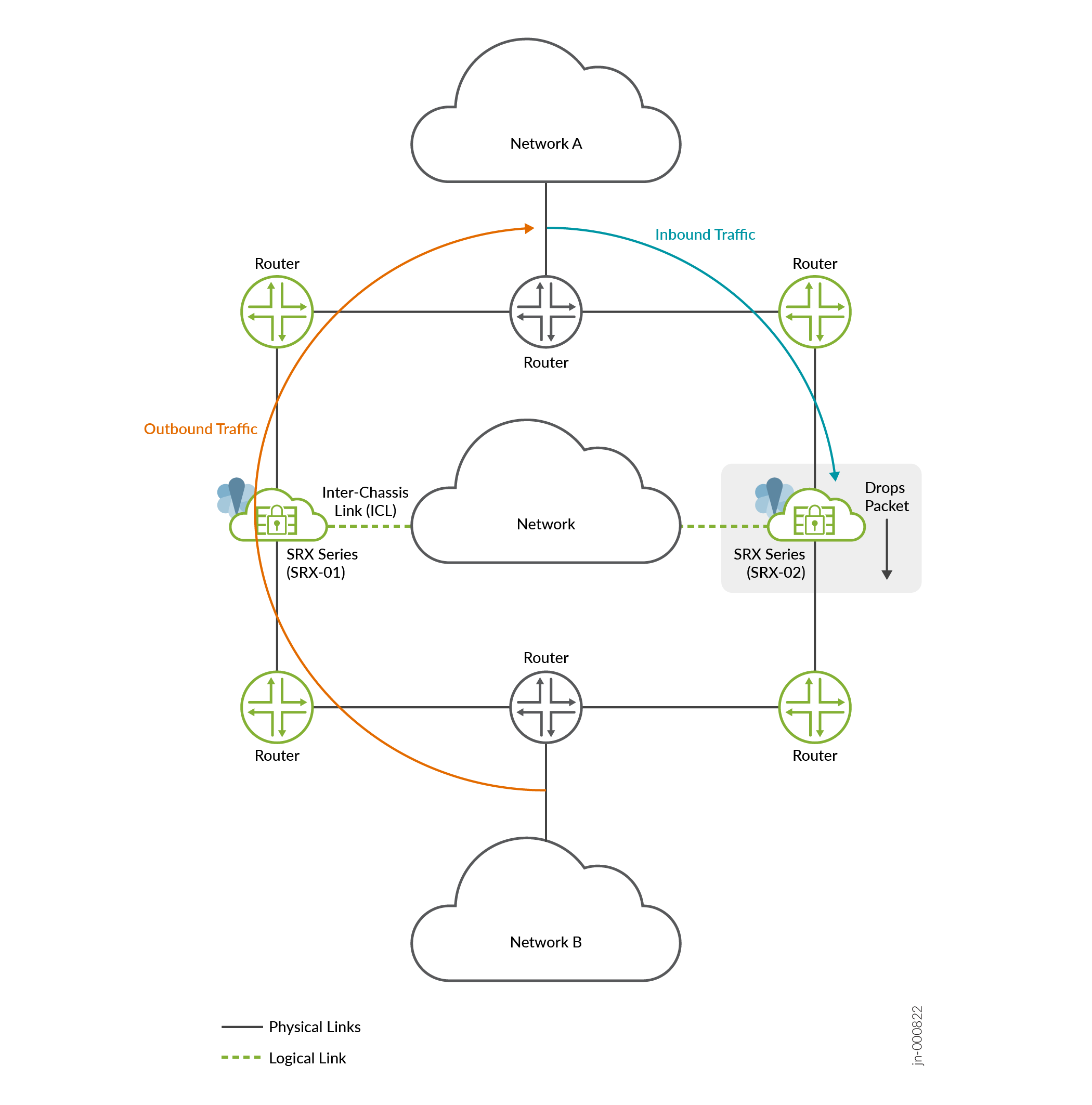
Outbound traffic from network B to network A passes through node 1 (SRX-01) and return traffic (inbound traffic) flows from network A to network B through node 2 (SRX-02).
In this case of asymmetric traffic flow, due to lack of complete state information about bidirectional traffic of the same flow, SRX Series Firewall (in this example SRX-02) drops packets.
With Asymmetric Traffic Flow Support
To support asymmetric traffic flow, Multinode High Availability uses Inter Chassis Datapath (ICD). The ICD forwards packets of asymmetric traffic flows between two SRX Series devices in a high availability setup.
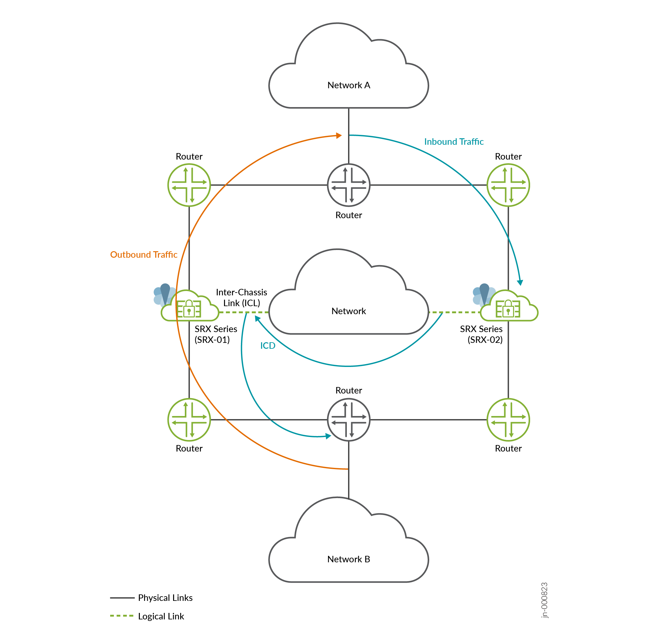
In this case, the Multinode High Availability system creates a new routable link between the nodes. This routable link enables the nodes to forward asymmetrical flows to the original node that can perform security inspection for the flow. That is, the node 2 (SRX-02) forwards the inbound traffic to the node 1 (SRX-01) instead to a next-hop router. The SRX Series Firewall performs security inspection for the packets of the bidirectional flow.
How Inter Chassis Datapath (ICD) Works?
Multinode High Availability ICD carries data traffic and forwards the data flows to the peer node. This link does not forward interchassis link (ICL) packets.
The workflow includes the following steps:
- When a Multinode High Availability node receives a data packet, security
services running on the node determines whether to forward the packet to
the peer node or process it locally. The decision to forward the packet
depends on:
- Packet's flow session states or service type
- State of SRG associated with the flow of the packet
- If the peer node is reachable over the ICD, security services on a node can send and receive packets between the nodes.
- Once the peer node receives a forwarded data packet through the ICD, it performs security inspection based on the configured policies.
To use ICD for packet forwarding between nodes, you must:
- Assign ICD to the loopback interface with a routable path to the other node.
- Ensure that the ICD has path diversity for the highest reliability by assigning multiple physical interfaces to the ICD.
Planning Interfaces for ICL and ICD
In a Multinode High Availability configuration, the ICL and ICD physical interfaces must be active and operational to accommodate asymmetric traffic flows. The ICL and ICD interfaces facilitate communication between nodes in the high availability setup, and their status will influence the packet processing. If either interface is non-functional, it will affect support for asymmetric traffic flows. Therefore, it is crucial to ensure the proper functioning of these interfaces for optimal network performance.
When you have multiple physical interfaces connected to the ICL, and one of these interfaces that's being actively used to process packets fails, the data flow switches to use another available physical interface associated with ICL. If all physical interfaces associated with ICL are down, SRX Series Firewalls lose the ICL connection. In this case, the SRX Series nodes can not exchange RTO messages and can not support asymmetric traffic flows.
Use different loopback interfaces for ICL and for ICD in a Multinode High Availability setup.
Nodes learn the route to reach IP address of the peer node's ICD through static or dynamic routing protocols (Example: BGP). Multinode High Availability setup leverages existing routing functionality on each SRX Series Firewall to route the packets.
ICL and ICD States Affecting Asymmetric Traffic
Table 1 shows how the states of BFD between the nodes are dependent on assigned physical interfaces of both ICL and ICD.
| ICL | ICD | Service for Asymmetric Traffic Flow | ||
| Physical Interface | BFD State | Physical interface | BFD State | |
| Up | Up | Up | Up | Up |
| Up | Up | Down | Down | Down |
| Down | Down | Up | Up | Down |
| Up | Down | Up | Down | Down |
| Down | Down | Down | Down | Down |
Configure Asymmetric Traffic Flow Support in Multinode High Availability
Read this topic to understand how to configure asymmetric traffic flow support for SRX Series Firewalls deployed in the Multinode High Availability solution. The example covers configuration in active/backup mode when SRX Series Firewalls are connected to routers on both sides (Layer 3 deployment).
Junos OS Release 23.4R1 brings in a new feature that supports asymmetric traffic flow. Asymmetric routing is a scenario where the path of packets in one direction is different from the origin path.
In a typical high availability deployment, you have multiple routers and switches on the both sides of the network. The routers use a next-hop path to forward each packet flow; but routers might not use the same path for the return traffic. In a Multinode High Availability setup, routers send packets to the firewall based on current routing path, which can result in asymmetric traffic flows
To handle asymmetric traffic flows, the Multinode High Availability infrastructure employs a new link known as Inter Chassis Datapath (ICD). ICD has the ability to forward the traffic between two nodes. It enables the nodes to redirect asymmetric traffic flows to the peer node that is originally in charge of providing stateful services for these flows.
Follow this configuration example to set up Multinode High Availability to support asymmetric routing and to validate the configuration on your device.
|
Reading Time |
Less than 15 minutes. |
|
Configuration Time |
Less than an hour. |
- Example Prerequisites
- Before You Begin
- Functional Overview
- Topology Illustration
- Topology Overview
- Configuration
- Verification
- Set Commands on All Devices
- Show Configuration Output
Example Prerequisites
Table 3 lists the hardware and software components that support the configuration.
|
Supported Hardware |
|
|
Supported Software |
Junos OS Release 23.4R1 |
|
Licensing requirements |
No separate license is required to configure Multinode High Availability. Licenses are unique to each SRX Series and cannot be shared between the nodes in a Multinode High Availability setup. Therefore, you must use identical licenses on both the nodes. |
In this example, we've used two supported SRX Series Firewalls with Junos OS Release 23.4R1 and two Juniper Networks(R) MX960 Universal Routing Platform as upstream and downstream routers.
Before You Begin
|
Benefits |
The SRX Series Firewall in a Multinode High Availability handles asymmetrically routed packets efficiently. This process ensures reliable and consistent handling of stateful services for these packets, improving overall performance and minimizing packet loss and inconsistencies in the network. |
|
Know more |
Functional Overview
Table 4 provides a quick summary of the configuration components deployed in this example.
|
Technologies used |
|
|
Primary verification tasks |
|
Topology Illustration
Figure 3 shows the topology used in this example.
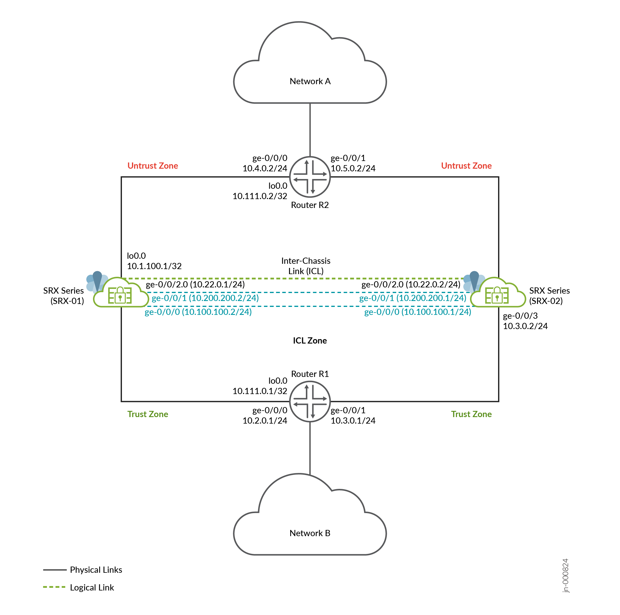
As shown in the topology, two SRX Series Firewalls are connected to adjacent routers on trust and untrust side forming a BGP neighborship.
An encrypted logical interchassis link (ICL) connects the nodes over a routed network. The nodes communicate with each other using a routable IP address (floating IP address) over the network. In general, you can use aggregated Ethernet (AE) or a revenue Ethernet port on the SRX Series Firewalls to setup an ICL connection. In this example, we've used GE ports for the ICL. We've also configured a routing instance for the ICL path to ensure maximum segmentation.
Two physical links (ICD) connect two SRX Series Firewalls. The physical interfaces on both the nodes are forming the MNHA ICD connections. In this example, use two dedicated revenue interfaces to configure ICD.
Loopback interfaces are used to host the IP addresses on SRX Series and routers.
In a typical high availability deployment, you have multiple routers and switches on the northbound and southbound sides of the network. For this example, we are using two routers on both sides of SRX Series Firewalls.
Topology Overview
In this example, you'll establish high availability between the SRX Series Firewalls and establish ICD (interchassis datapath) for providing support to handle asymmetric routing support.
In a typical high availability deployment, you have multiple routers and switches on the northbound and southbound sides of the network. For this example, we are using two routers on both sides of SRX Series Firewalls.
Table 5 and Table 6 show the details on interfaces configuration used in this example.
| Device | Interface | Zone | IP Address | Configured For |
|---|---|---|---|---|
| SRX-01 | lo0 | Trust | 10.1.100.1/32 |
Local forwarding address used to forward data packet over ICD link. |
| ge-0/0/2 | ICL-Zone | 10.22.0.1/24 | Interchassis link (ICL) | |
| ge-0/0/1 and ge-0/0/0 | Trust |
|
Interchassis Datalink connecting two SRX Series Firewalls | |
| ge-0/0/4 | Untrust | 10.4.0.1/24 | Connects to R2 router | |
| ge-0/0/3 | Trust | 10.2.0.2/24 | Connects to R1 router | |
| SRX-02 | lo0 | Trust | 10.1.200.1/32 |
Local forwarding address used to forward data packet over ICD link. |
| ge-0/0/2 | ICL-zone | 10.22.0.2/24 | Interchassis link (ICL) | |
|
Trust |
|
Interchassis Data link (ICD) | |
| ge-0/0/3 | Trust | 10.3.0.2/24 | Connects to R1 router | |
| ge-0/0/4 | Untrust | 10.5.0.1/24 | Connects to R2 router |
Interfaces and IP Address Configuration on Routing Devices
| Device | Interface | IP Address | Configured for |
|---|---|---|---|
| R2 | lo0 | 10.111.0.2/32 | Loopback interface address of R2 |
| ge-0/0/0 | 10.4.0.2/24 | Connects to SRX-02 | |
| ge-0/0/1 | 10.5.0.2/24 | Connects to SRX-01 | |
| ge-0/0/2 | 10.6.0.1/24 | Connects to external network | |
| R1 | lo0 | 10.111.0.1/32 | Loopback interface address of R1 |
| ge-0/0/0 | 10.2.0.1/24 | Connects to SRX-01 | |
| ge-0/0/1 | 10.3.0.1/24 | Connects to SRX-02 | |
| ge-0/0/2 | 10.1.0.1/24 | Connects to internal network |
Configuration
For complete sample configurations on the DUT, see:
Junos IKE package is required on your SRX Series Firewalls for Multinode High Availability configuration. This package is available as a default package or as an optional package on SRX Series Firewalls. See Support for Junos IKE Package for details.
If the package is not installed by default on your SRX Series firewall, use the request system software add optional://junos-ike.tgz to install it. You require this step for ICL encryption.
Verification
Use the following show commands to verify the feature in this example.
| Commands | Verification Task |
|---|---|
| show chassis high availability information |
Displays Multinode High Availability details including status. |
|
show chassis high-availability data-plane statistics |
Displays ICD data packets statistics. |
Check Multinode High Availability Details
Purpose
View and verify the details of the Multinode High Availability setup configured on your security device.
Action
From operational mode, run the following command:
SRX-01
user@srx-01> show chassis high-availability information

Node failure codes:
    HW  Hardware monitoring    LB  Loopback monitoring
    MB  Mbuf monitoring        SP  SPU monitoring
    CS  Cold Sync monitoring   SU  Software Upgrade

Node Status: ONLINE
Local-id: 1
Local-IP: 10.22.0.1
Local Forwarding IP: 10.1.100.1
HA Peer Information:

    Peer Id: 2        IP address: 10.22.0.2     Interface: ge-0/0/2.0
    Routing Instance: default
    Encrypted: YES    Conn State: UP
    Configured BFD Detection Time: 5 * 400ms
    Cold Sync Status: COMPLETE
    Peer Forwarding IP: 10.1.200.1               Interface: lo0.0
    Peer ICD Conn State: UP

Services Redundancy Group: 0
        Current State: ONLINE
        Peer Information:
          Peer Id: 2

SRG failure event codes:
    BF  BFD monitoring
    IP  IP monitoring
    IF  Interface monitoring
    CP  Control Plane monitoring

Services Redundancy Group: 1
        Deployment Type: ROUTING
        Status: INELIGIBLE
        Activeness Priority: 200
        Preemption: ENABLED
        Process Packet In Backup State: NO
        Control Plane State: N/A
        System Integrity Check: COMPLETE
        Failure Events: [ IP ]
        Peer Information:
          Peer Id: 2
          Status : ACTIVE
          Health Status: HEALTHY
          Failover Readiness: N/A
SRX-02
user@srx-02> show chassis high-availability information

Node failure codes:
    HW  Hardware monitoring    LB  Loopback monitoring
    MB  Mbuf monitoring        SP  SPU monitoring
    CS  Cold Sync monitoring   SU  Software Upgrade

Node Status: ONLINE
Local-id: 2
Local-IP: 10.22.0.2
Local Forwarding IP: 10.1.200.1
HA Peer Information:

    Peer Id: 1        IP address: 10.22.0.1     Interface: ge-0/0/2.0
    Routing Instance: default
    Encrypted: YES    Conn State: UP
    Configured BFD Detection Time: 5 * 400ms
    Cold Sync Status: COMPLETE
    Peer Forwarding IP: 10.1.100.1               Interface: lo0.0
    Peer ICD Conn State: UP

Services Redundancy Group: 0
        Current State: ONLINE
        Peer Information:
          Peer Id: 1

SRG failure event codes:
    BF  BFD monitoring
    IP  IP monitoring
    IF  Interface monitoring
    CP  Control Plane monitoring

Services Redundancy Group: 1
        Deployment Type: ROUTING
        Status: ACTIVE
        Activeness Priority: 1
        Preemption: DISABLED
        Process Packet In Backup State: NO
        Control Plane State: READY
        System Integrity Check: N/A
        Failure Events: NONE
        Peer Information:
          Peer Id: 1
          Status : INELIGIBLE
          Health Status: UNHEALTHY
          Failover Readiness: NOT READY
Meaning
Verify these details from the command output:
-
Local node and peer node details such as IP address and ID.
-
The field
Peer ICD Conn State: UPindicates that the ICD link is established and operational.
Verify ICD Data Packets Statistics
Purpose
Check if the ICD is operational and facilitating the transfer of data packets between the nodes.
Action
From operational mode, run the following command:
user@srx-01> show chassis high-availability data-plane statistics
Services Synchronized:
    Service name                              RTOs sent    RTOs received
    Translation context                       0            0
    Incoming NAT                              0            0
    Resource manager                          0            0
    DS-LITE create                            0            0
    Session create                            0            0
    IPv6 session create                       0            0
    IPv4/6 session RTO ACK                    0            0
    Session close                             0            0
    IPv6 session close                        0            0
    Session change                            0            0
    IPv6 session change                       0            0
    ALG Support Library                       0            0
    Gate create                               0            0
    Session ageout refresh requests           0            0
    IPv6 session ageout refresh requests      0            0
    Session ageout refresh replies            0            0
    IPv6 session ageout refresh replies       0            0
    IPSec VPN                                 0            0
    Firewall user authentication              0            0
    MGCP ALG                                  0            0
    H323 ALG                                  0            0
    SIP ALG                                   0            0
    SCCP ALG                                  0            0
    PPTP ALG                                  0            0
    JSF PPTP ALG                              0            0
    RPC ALG                                   0            0
    RTSP ALG                                  0            0
    RAS ALG                                   0            0
    MAC address learning                      0            0
    GPRS GTP                                  0            0
    GPRS SCTP                                 0            0
    GPRS FRAMEWORK                            0            0
    JSF RTSP ALG                              0            0
    JSF SUNRPC MAP                            0            0
    JSF MSRPC MAP                             0            0
    DS-LITE delete                            0            0
    JSF SLB                                   0            0
    APPID                                     0            0
    JSF MGCP MAP                              0            0
    JSF H323 ALG                              0            0
    JSF RAS ALG                               0            0
    JSF SCCP MAP                              0            0
    JSF SIP MAP                               0            0
    PST_NAT_CREATE                            0            0
    PST_NAT_CLOSE                             0            0
    PST_NAT_UPDATE                            0            0
    JSF TCP STACK                             0            0
    JSF IKE ALG                               0            0

Packet stats                              Pkts sent    Pkts received
    ICD Data                                  1035          1286
Meaning
The field ICD Data indicates ICD is routing asymmetric
traffic flow in Multinode High Availability setup.
Set Commands on All Devices
Set command output on all devices.
SRX-01 (Node 1)
set chassis high-availability local-id 1
set chassis high-availability local-id local-ip 10.22.0.1
set chassis high-availability local-id local-forwarding-ip 10.1.100.1
set chassis high-availability peer-id 2 peer-ip 10.22.0.2
set chassis high-availability peer-id 2 interface ge-0/0/2.0
set chassis high-availability peer-id 2 vpn-profile IPSEC_VPN_ICL
set chassis high-availability peer-id 2 peer-forwarding-ip 10.1.200.1
set chassis high-availability peer-id 2 peer-forwarding-ip interface lo0.0
set chassis high-availability peer-id 2 peer-forwarding-ip liveness-detection minimum-interval 1000
set chassis high-availability peer-id 2 peer-forwarding-ip liveness-detection multiplier 5
set chassis high-availability peer-id 2 liveness-detection minimum-interval 400
set chassis high-availability peer-id 2 liveness-detection multiplier 5
set chassis high-availability services-redundancy-group 0 peer-id 2
set chassis high-availability services-redundancy-group 1 deployment-type routing
set chassis high-availability services-redundancy-group 1 peer-id 2
set chassis high-availability services-redundancy-group 1 activeness-probe dest-ip 10.111.0.1
set chassis high-availability services-redundancy-group 1 activeness-probe dest-ip src-ip 10.11.0.1
set chassis high-availability services-redundancy-group 1 monitor ip 10.10.10.1
set chassis high-availability services-redundancy-group 1 monitor bfd-liveliness 10.4.0.2 src-ip 10.4.0.1
set chassis high-availability services-redundancy-group 1 monitor bfd-liveliness 10.4.0.2 session-type singlehop
set chassis high-availability services-redundancy-group 1 monitor bfd-liveliness 10.4.0.2 interface ge-0/0/4.0
set chassis high-availability services-redundancy-group 1 monitor interface ge-0/0/1
set chassis high-availability services-redundancy-group 1 active-signal-route 10.39.1.1
set chassis high-availability services-redundancy-group 1 backup-signal-route 10.39.1.2
set chassis high-availability services-redundancy-group 1 preemption
set chassis high-availability services-redundancy-group 1 activeness-priority 200
set security pki ca-profile Root-CA ca-identity Root-CA
set security pki ca-profile Root-CA enrollment url http://10.157.69.204/certsrv/mscep/mscep.dll
set security pki ca-profile Root-CA revocation-check disable
set security ike proposal MNHA_IKE_PROP description mnha_link_encr_tunnel
set security ike proposal MNHA_IKE_PROP authentication-method pre-shared-keys
set security ike proposal MNHA_IKE_PROP dh-group group14
set security ike proposal MNHA_IKE_PROP authentication-algorithm sha-256
set security ike proposal MNHA_IKE_PROP encryption-algorithm aes-256-cbc
set security ike proposal MNHA_IKE_PROP lifetime-seconds 3600
set security ike policy MNHA_IKE_POL description mnha_link_encr_tunnel
set security ike policy MNHA_IKE_POL proposals MNHA_IKE_PROP
set security ike policy MNHA_IKE_POL pre-shared-key ascii-text "$ABC123"
set security ike gateway MNHA_IKE_GW ike-policy MNHA_IKE_POL
set security ike gateway MNHA_IKE_GW version v2-only
set security ipsec proposal MNHA_IPSEC_PROP description mnha_link_encr_tunnel
set security ipsec proposal MNHA_IPSEC_PROP protocol esp
set security ipsec proposal MNHA_IPSEC_PROP encryption-algorithm aes-256-gcm
set security ipsec proposal MNHA_IPSEC_PROP lifetime-seconds 3600
set security ipsec policy MNHA_IPSEC_POL description mnha_link_encr_tunnel
set security ipsec policy MNHA_IPSEC_POL proposals MNHA_IPSEC_PROP
set security ipsec vpn IPSEC_VPN_ICL ha-link-encryption
set security ipsec vpn IPSEC_VPN_ICL ike gateway MNHA_IKE_GW
set security ipsec vpn IPSEC_VPN_ICL ike ipsec-policy MNHA_IPSEC_POL
set security policies default-policy permit-all
set security zones security-zone untrust host-inbound-traffic system-services ike
set security zones security-zone untrust host-inbound-traffic system-services ping
set security zones security-zone untrust host-inbound-traffic protocols bfd
set security zones security-zone untrust host-inbound-traffic protocols bgp
set security zones security-zone untrust interfaces ge-0/0/4.0
set security zones security-zone trust host-inbound-traffic system-services all
set security zones security-zone trust host-inbound-traffic protocols all
set security zones security-zone trust interfaces ge-0/0/3.0
set security zones security-zone trust interfaces ge-0/0/1.0
set security zones security-zone trust interfaces ge-0/0/0.0
set security zones security-zone trust interfaces lo0.0
set security zones security-zone icl-zone host-inbound-traffic system-services ike
set security zones security-zone icl-zone host-inbound-traffic system-services ping
set security zones security-zone icl-zone host-inbound-traffic system-services high-availability
set security zones security-zone icl-zone host-inbound-traffic system-services ssh
set security zones security-zone icl-zone host-inbound-traffic protocols bfd
set security zones security-zone icl-zone host-inbound-traffic protocols bgp
set security zones security-zone icl-zone interfaces ge-0/0/2.0
set interfaces ge-0/0/0 description icd-1
set interfaces ge-0/0/0 unit 0 family inet address 10.100.100.2/24
set interfaces ge-0/0/1 description icd-2
set interfaces ge-0/0/1 unit 0 family inet address 10.200.200.2/24
set interfaces ge-0/0/2 description interchassis_link
set interfaces ge-0/0/2 unit 0 family inet address 10.22.0.1/24
set interfaces ge-0/0/3 description trust
set interfaces ge-0/0/3 unit 0 family inet address 10.2.0.2/24
set interfaces ge-0/0/4 description untrust
set interfaces ge-0/0/4 unit 0 family inet address 10.4.0.1/24
set interfaces lo0 description trust
set interfaces lo0 unit 0 family inet address 10.1.100.1/32
set policy-options policy-statement mnha-route-policy term 1 from protocol static
set policy-options policy-statement mnha-route-policy term 1 from protocol direct
set policy-options policy-statement mnha-route-policy term 1 from condition active_route_exists
set policy-options policy-statement mnha-route-policy term 1 then metric 10
set policy-options policy-statement mnha-route-policy term 1 then accept
set policy-options policy-statement mnha-route-policy term 2 from protocol static
set policy-options policy-statement mnha-route-policy term 2 from protocol direct
set policy-options policy-statement mnha-route-policy term 2 from condition backup_route_exists
set policy-options policy-statement mnha-route-policy term 2 then metric 20
set policy-options policy-statement mnha-route-policy term 2 then accept
set policy-options policy-statement mnha-route-policy term 3 from protocol static
set policy-options policy-statement mnha-route-policy term 3 from protocol direct
set policy-options policy-statement mnha-route-policy term 3 then metric 30
set policy-options policy-statement mnha-route-policy term 3 then accept
set policy-options policy-statement mnha-route-policy term default then reject
set policy-options condition active_route_exists if-route-exists address-family inet 10.39.1.1/32
set policy-options condition active_route_exists if-route-exists address-family inet table inet.0
set policy-options condition backup_route_exists if-route-exists address-family inet 10.39.1.2/32
set policy-options condition backup_route_exists if-route-exists address-family inet table inet.0
set protocols bgp group trust type internal
set protocols bgp group trust local-address 10.2.0.2
set protocols bgp group trust export mnha-route-policy
set protocols bgp group trust local-as 65000
set protocols bgp group trust bfd-liveness-detection minimum-interval 500
set protocols bgp group trust bfd-liveness-detection minimum-receive-interval 500
set protocols bgp group trust bfd-liveness-detection multiplier 3
set protocols bgp group trust neighbor 10.2.0.1
set protocols bgp group untrust type internal
set protocols bgp group untrust local-address 10.4.0.1
set protocols bgp group untrust export mnha-route-policy
set protocols bgp group untrust local-as 65000
set protocols bgp group untrust bfd-liveness-detection minimum-interval 500
set protocols bgp group untrust bfd-liveness-detection minimum-receive-interval 500
set protocols bgp group untrust bfd-liveness-detection multiplier 3
set protocols bgp group untrust neighbor 10.4.0.2
set routing-options autonomous-system 65000
set routing-options static route 10.1.0.0/24 next-hop 10.2.0.1
set routing-options static route 10.6.0.0/24 next-hop 10.4.0.2
set routing-options static route 10.111.0.1/32 next-hop 10.2.0.1
set routing-options static route 10.111.0.2/32 next-hop 10.4.0.2
set routing-options static route 10.1.200.1/32 next-hop 10.200.200.1
set routing-options static route 10.1.200.1/32 next-hop 10.100.100.1
SRX-02 (Node 2)
set chassis high-availability local-id 2
set chassis high-availability local-id local-ip 10.22.0.2
set chassis high-availability local-id local-forwarding-ip 200.1.1.1
set chassis high-availability peer-id 1 peer-ip 10.22.0.1
set chassis high-availability peer-id 1 interface ge-0/0/2.0
set chassis high-availability peer-id 1 vpn-profile IPSEC_VPN_ICL
set chassis high-availability peer-id 1 peer-forwarding-ip 100.1.1.1
set chassis high-availability peer-id 1 peer-forwarding-ip interface lo0.0
set chassis high-availability peer-id 1 peer-forwarding-ip liveness-detection minimum-interval 1000
set chassis high-availability peer-id 1 peer-forwarding-ip liveness-detection multiplier 5
set chassis high-availability peer-id 1 liveness-detection minimum-interval 400
set chassis high-availability peer-id 1 liveness-detection multiplier 5
set chassis high-availability services-redundancy-group 0 peer-id 1
set chassis high-availability services-redundancy-group 1 deployment-type routing
set chassis high-availability services-redundancy-group 1 peer-id 1
set chassis high-availability services-redundancy-group 1 activeness-probe dest-ip 10.111.0.1
set chassis high-availability services-redundancy-group 1 activeness-probe dest-ip src-ip 10.11.0.1
set chassis high-availability services-redundancy-group 1 monitor bfd-liveliness 10.5.0.2 src-ip 10.5.0.1
set chassis high-availability services-redundancy-group 1 monitor bfd-liveliness 10.5.0.2 session-type singlehop
set chassis high-availability services-redundancy-group 1 monitor bfd-liveliness 10.5.0.2 interface ge-0/0/4.0
set chassis high-availability services-redundancy-group 1 active-signal-route 10.39.1.1
set chassis high-availability services-redundancy-group 1 backup-signal-route 10.39.1.2
set chassis high-availability services-redundancy-group 1 activeness-priority 1
set security pki ca-profile Root-CA ca-identity Root-CA
set security pki ca-profile Root-CA enrollment url http://10.157.69.204/certsrv/mscep/mscep.dll
set security pki ca-profile Root-CA revocation-check disable
set security ike proposal MNHA_IKE_PROP description mnha_link_encr_tunnel
set security ike proposal MNHA_IKE_PROP authentication-method pre-shared-keys
set security ike proposal MNHA_IKE_PROP dh-group group14
set security ike proposal MNHA_IKE_PROP authentication-algorithm sha-256
set security ike proposal MNHA_IKE_PROP encryption-algorithm aes-256-cbc
set security ike proposal MNHA_IKE_PROP lifetime-seconds 3600
set security ike policy MNHA_IKE_POL description mnha_link_encr_tunnel
set security ike policy MNHA_IKE_POL proposals MNHA_IKE_PROP
set security ike policy MNHA_IKE_POL pre-shared-key ascii-text "$ABC123"
set security ike gateway MNHA_IKE_GW ike-policy MNHA_IKE_POL
set security ike gateway MNHA_IKE_GW version v2-only
set security ipsec proposal MNHA_IPSEC_PROP description mnha_link_encr_tunnel
set security ipsec proposal MNHA_IPSEC_PROP protocol esp
set security ipsec proposal MNHA_IPSEC_PROP encryption-algorithm aes-256-gcm
set security ipsec proposal MNHA_IPSEC_PROP lifetime-seconds 3600
set security ipsec policy MNHA_IPSEC_POL description mnha_link_encr_tunnel
set security ipsec policy MNHA_IPSEC_POL proposals MNHA_IPSEC_PROP
set security ipsec vpn IPSEC_VPN_ICL ha-link-encryption
set security ipsec vpn IPSEC_VPN_ICL ike gateway MNHA_IKE_GW
set security ipsec vpn IPSEC_VPN_ICL ike ipsec-policy MNHA_IPSEC_POL
set security policies default-policy permit-all
set security zones security-zone untrust host-inbound-traffic system-services ike
set security zones security-zone untrust host-inbound-traffic system-services ping
set security zones security-zone untrust host-inbound-traffic protocols bfd
set security zones security-zone untrust host-inbound-traffic protocols bgp
set security zones security-zone untrust interfaces ge-0/0/4.0
set security zones security-zone trust host-inbound-traffic system-services all
set security zones security-zone trust host-inbound-traffic protocols all
set security zones security-zone trust interfaces ge-0/0/3.0
set security zones security-zone trust interfaces lo0.0
set security zones security-zone trust interfaces ge-0/0/1.0
set security zones security-zone trust interfaces ge-0/0/0.0
set security zones security-zone icl-zone host-inbound-traffic system-services ike
set security zones security-zone icl-zone host-inbound-traffic system-services ping
set security zones security-zone icl-zone host-inbound-traffic system-services high-availability
set security zones security-zone icl-zone host-inbound-traffic system-services ssh
set security zones security-zone icl-zone host-inbound-traffic protocols bfd
set security zones security-zone icl-zone host-inbound-traffic protocols bgp
set security zones security-zone icl-zone interfaces ge-0/0/2.0
set interfaces ge-0/0/0 description icd-1
set interfaces ge-0/0/0 unit 0 family inet address 10.100.100.1/24
set interfaces ge-0/0/1 description icd-2
set interfaces ge-0/0/1 unit 0 family inet address 10.200.200.1/24
set interfaces ge-0/0/2 description interchassis_link
set interfaces ge-0/0/2 unit 0 family inet address 10.22.0.2/24
set interfaces ge-0/0/3 description trust
set interfaces ge-0/0/3 unit 0 family inet address 10.3.0.2/24
set interfaces ge-0/0/4 description untrust
set interfaces ge-0/0/4 unit 0 family inet address 10.5.0.1/24
set interfaces lo0 description trust
set interfaces lo0 unit 0 family inet address 10.1.200.1/32
set policy-options route-filter-list ipsec 10.6.0.0/16 orlonger
set policy-options route-filter-list loopback 10.11.0.0/24 orlonger
set policy-options policy-statement mnha-route-policy term 1 from protocol static
set policy-options policy-statement mnha-route-policy term 1 from protocol direct
set policy-options policy-statement mnha-route-policy term 1 from condition active_route_exists
set policy-options policy-statement mnha-route-policy term 1 then metric 10
set policy-options policy-statement mnha-route-policy term 1 then accept
set policy-options policy-statement mnha-route-policy term 2 from protocol static
set policy-options policy-statement mnha-route-policy term 2 from protocol direct
set policy-options policy-statement mnha-route-policy term 2 from condition backup_route_exists
set policy-options policy-statement mnha-route-policy term 2 then metric 20
set policy-options policy-statement mnha-route-policy term 2 then accept
set policy-options policy-statement mnha-route-policy term 3 from protocol static
set policy-options policy-statement mnha-route-policy term 3 from protocol direct
set policy-options policy-statement mnha-route-policy term 3 then metric 35
set policy-options policy-statement mnha-route-policy term 3 then accept
set policy-options policy-statement mnha-route-policy term default then reject
set policy-options condition active_route_exists if-route-exists address-family inet 10.39.1.1/32
set policy-options condition active_route_exists if-route-exists address-family inet table inet.0
set policy-options condition backup_route_exists if-route-exists address-family inet 10.39.1.2/32
set policy-options condition backup_route_exists if-route-exists address-family inet table inet.0
set protocols bgp group trust type internal
set protocols bgp group trust local-address 10.3.0.2
set protocols bgp group trust export mnha-route-policy
set protocols bgp group trust local-as 65000
set protocols bgp group trust bfd-liveness-detection minimum-interval 500
set protocols bgp group trust bfd-liveness-detection minimum-receive-interval 500
set protocols bgp group trust bfd-liveness-detection multiplier 3
set protocols bgp group trust neighbor 10.3.0.1
set protocols bgp group untrust type internal
set protocols bgp group untrust local-address 10.5.0.1
set protocols bgp group untrust export mnha-route-policy
set protocols bgp group untrust local-as 65000
set protocols bgp group untrust bfd-liveness-detection minimum-interval 500
set protocols bgp group untrust bfd-liveness-detection minimum-receive-interval 500
set protocols bgp group untrust bfd-liveness-detection multiplier 3
set protocols bgp group untrust neighbor 10.5.0.2
set routing-options autonomous-system 65000
set routing-options static route 10.1.0.0/24 next-hop 10.3.0.1
set routing-options static route 10.6.0.0/24 next-hop 10.5.0.2
set routing-options static route 10.111.0.1/32 next-hop 10.3.0.1
set routing-options static route 10.111.0.2/32 next-hop 10.5.0.2
set routing-options static route 10.1.100.1/32 next-hop 10.200.200.2
set routing-options static route 10.1.100.1/32 next-hop 10.100.100.2
Router -1
set interfaces ge-0/0/0 description ha
set interfaces ge-0/0/0 unit 0 family inet address 10.2.0.1/24
set interfaces ge-0/0/1 description ha
set interfaces ge-0/0/1 unit 0 family inet address 10.3.0.1/24
set interfaces ge-0/0/2 description lan
set interfaces ge-0/0/2 unit 0 family inet address 10.1.0.1/24
set interfaces lo0 description loopback
set interfaces lo0 unit 0 family inet address 10.111.0.1/32 primary
set interfaces lo0 unit 0 family inet address 10.111.0.1/32 preferred
set routing-options autonomous-system 65000
set protocols bgp group mnha_r0 type internal
set protocols bgp group mnha_r0 local-address 10.2.0.1
set protocols bgp group mnha_r0 local-as 65000
set protocols bgp group mnha_r0 bfd-liveness-detection minimum-interval 500
set protocols bgp group mnha_r0 bfd-liveness-detection minimum-receive-interval 500
set protocols bgp group mnha_r0 bfd-liveness-detection multiplier 3
set protocols bgp group mnha_r0 neighbor 10.2.0.2
set protocols bgp group mnha_r0_b type internal
set protocols bgp group mnha_r0_b local-address 10.3.0.1
set protocols bgp group mnha_r0_b local-as 65000
set protocols bgp group mnha_r0_b bfd-liveness-detection minimum-interval 500
set protocols bgp group mnha_r0_b bfd-liveness-detection minimum-receive-interval 500
set protocols bgp group mnha_r0_b bfd-liveness-detection multiplier 3
set protocols bgp group mnha_r0_b neighbor 10.3.0.2
Router-2
set interfaces ge-0/0/0 description HA
set interfaces ge-0/0/0 unit 0 family inet address 10.4.0.2/24
set interfaces ge-0/0/1 description HA
set interfaces ge-0/0/1 unit 0 family inet address 10.5.0.2/24
set interfaces ge-0/0/2 description trust
set interfaces ge-0/0/2 unit 0 family inet address 10.6.0.1/24
set interfaces lo0 description loopback
set interfaces lo0 unit 0 family inet address 10.111.0.2/32 primary
set interfaces lo0 unit 0 family inet address 10.111.0.2/32 preferred
set routing-options autonomous-system 65000
set protocols bgp group mnha_r0 type internal
set protocols bgp group mnha_r0 local-address 10.4.0.2
set protocols bgp group mnha_r0 local-as 65000
set protocols bgp group mnha_r0 bfd-liveness-detection minimum-interval 500
set protocols bgp group mnha_r0 bfd-liveness-detection minimum-receive-interval 500
set protocols bgp group mnha_r0 bfd-liveness-detection multiplier 3
set protocols bgp group mnha_r0 neighbor 10.4.0.1
set protocols bgp group mnha_r0_b type internal
set protocols bgp group mnha_r0_b local-address 10.5.0.2
set protocols bgp group mnha_r0_b local-as 65000
set protocols bgp group mnha_r0_b bfd-liveness-detection minimum-interval 500
set protocols bgp group mnha_r0_b bfd-liveness-detection minimum-receive-interval 500
set protocols bgp group mnha_r0_b bfd-liveness-detection multiplier 3
set protocols bgp group mnha_r0_b neighbor 10.5.0.1
Show Configuration Output
From configuration mode, confirm your configuration by entering the show
high availability, , show security zones, and
show interfaces. If the output does not display the
intended configuration, repeat the configuration instructions in this example to
correct it.
SRX-01 (Node 1)
user@srx-01# show chassis high-availability
local-id {
    1;
    local-ip 10.22.0.1;
    local-forwarding-ip 100.1.1.1;
}
peer-id 2 {
    peer-ip 10.22.0.2;
    interface ge-0/0/2.0;
    vpn-profile IPSEC_VPN_ICL;
    peer-forwarding-ip {
        200.1.1.1;
        interface lo0.0;
        liveness-detection {
            minimum-interval 1000;
            multiplier 5;
        }
    }
    liveness-detection {
        minimum-interval 400;
        multiplier 5;
    }
}
services-redundancy-group 0 {
    peer-id {
        2;
    }
}
services-redundancy-group 1 {
    deployment-type routing;
    peer-id {
        2;
    }
    activeness-probe {
        dest-ip {
            10.111.0.1;
            src-ip 10.11.0.1;
        }
    }
    monitor {
        ip 10.10.10.1;
        bfd-liveliness 10.4.0.2 {
            src-ip 10.4.0.1;
            session-type singlehop;
            interface ge-0/0/4.0;
        }
        interface {
            ge-0/0/1;
        }
    }
    active-signal-route {
        10.39.1.1;
    }
    backup-signal-route {
        10.39.1.2;
    }
    preemption;
    activeness-priority 200;
}
user@srx-01# show interfaces
ge-0/0/0 {
    description icd-1;
    unit 0 {
        family inet {
            address 10.100.100.2/24;
        }
    }
}
ge-0/0/1 {
    description icd-2;
    unit 0 {
        family inet {
            address 10.200.200.2/24;
        }
    }
}
ge-0/0/2 {
    description interchassis_link;
    unit 0 {
        family inet {
            address 10.22.0.1/24;
        }
    }
}
ge-0/0/3 {
    description trust;
    unit 0 {
        family inet {
            address 10.2.0.2/24;
        }
    }
}
ge-0/0/4 {
    description untrust;
    unit 0 {
        family inet {
            address 10.4.0.1/24;
        }
    }
}
lo0 {
    description trust;
    unit 0 {
        family inet {
            address 10.1.100.1/32;
        }
    }
}
user@srx-01# show security zones
security-zone untrust {
    host-inbound-traffic {
        system-services {
            ike;
            ping;
        }
        protocols {
            bfd;
            bgp;
        }
    }
    interfaces {
        ge-0/0/4.0;
    }
}
security-zone trust {
    host-inbound-traffic {
        system-services {
            all;
        }
        protocols {
            all;
        }
    }
    interfaces {
        ge-0/0/3.0;
        ge-0/0/1.0;
        ge-0/0/0.0;
        lo0.0;
    }
}
security-zone icl-zone {
    host-inbound-traffic {
        system-services {
            ike;
            ping;
            high-availability;
            ssh;
        }
        protocols {
            bfd;
            bgp;
        }
    }
    interfaces {
        ge-0/0/2.0;
    }
}
user@srx-01# show policy-options
policy-statement mnha-route-policy {
    term 1 {
        from {
            protocol [ static direct ];
            condition active_route_exists;
        }
        then {
            metric 10;
            accept;
        }
    }
    term 2 {
        from {
            protocol [ static direct ];
            condition backup_route_exists;
        }
        then {
            metric 20;
            accept;
        }
    }
    term 3 {
        from protocol [ static direct ];
        then {
            metric 30;
            accept;
        }
    }
    term default {
        then reject;
    }
}
condition active_route_exists {
    if-route-exists {
        address-family {
            inet {
                10.39.1.1/32;
                table inet.0;
            }
        }
    }
}
condition backup_route_exists {
    if-route-exists {
        address-family {
            inet {
                10.39.1.2/32;
                table inet.0;
            }
        }
    }
}
user@srx-01# show routing-options
autonomous-system 65000;
static {
    route 10.1.0.0/24 next-hop 10.2.0.1;
    route 10.6.0.0/24 next-hop 10.4.0.2;
    route 10.111.0.1/32 next-hop 10.2.0.1;
    route 10.111.0.2/32 next-hop 10.4.0.2;
    route 10.1.200.1/32 next-hop [ 10.200.200.1 10.100.100.1 ];
}
SRX-02 (Node 2)
user@srx-02# show chassis high-availability
local-id {
    2;
    local-ip 10.22.0.2;
    local-forwarding-ip 200.1.1.1;
}
peer-id 1 {
    peer-ip 10.22.0.1;
    interface ge-0/0/2.0;
    vpn-profile IPSEC_VPN_ICL;
    peer-forwarding-ip {
        100.1.1.1;
        interface lo0.0;
        liveness-detection {
            minimum-interval 1000;
            multiplier 5;
        }
    }
    liveness-detection {
        minimum-interval 400;
        multiplier 5;
    }
}
services-redundancy-group 0 {
    peer-id {
        1;
    }
}
services-redundancy-group 1 {
    deployment-type routing;
    peer-id {
        1;
    }
    activeness-probe {
        dest-ip {
            10.111.0.1;
            src-ip 10.11.0.1;
        }
    }
    monitor {
        bfd-liveliness 10.5.0.2 {
            src-ip 10.5.0.1;
            session-type singlehop;
            interface ge-0/0/4.0;
        }
    }
    active-signal-route {
        10.39.1.1;
    }
    backup-signal-route {
        10.39.1.2;
    }
    activeness-priority 1;
}
user@srx-02# show security zones
security-zone untrust {
    host-inbound-traffic {
        system-services {
            ike;
            ping;
        }
        protocols {
            bfd;
            bgp;
        }
    }
    interfaces {
        ge-0/0/4.0;
    }
}
security-zone trust {
    host-inbound-traffic {
        system-services {
            all;
        }
        protocols {
            all;
        }
    }
    interfaces {
        ge-0/0/3.0;
        lo0.0;
        ge-0/0/1.0;
        ge-0/0/0.0;
    }
}
security-zone icl-zone {
    host-inbound-traffic {
        system-services {
            ike;
            ping;
            high-availability;
            ssh;
        }
        protocols {
            bfd;
            bgp;
        }
    }
    interfaces {
        ge-0/0/2.0;
    }
}
user@srx-02# show interfaces
ge-0/0/0 {
    description icd-1;
    unit 0 {
        family inet {
            address 10.100.100.1/24;
        }
    }
}
ge-0/0/1 {
    description icd-2;
    unit 0 {
        family inet {
            address 10.200.200.1/24;
        }
    }
}
ge-0/0/2 {
    description interchassis_link;
    unit 0 {
        family inet {
            address 10.22.0.2/24;
        }
    }
}
ge-0/0/3 {
    description trust;
    unit 0 {
        family inet {
            address 10.3.0.2/24;
        }
    }
}
ge-0/0/4 {
    description untrust;
    unit 0 {
        family inet {
            address 10.5.0.1/24;
        }
    }
}
lo0 {
    description trust;
    unit 0 {
        family inet {
            address 10.1.200.1/32;
        }
    }
}
user@srx-02# show policy-options

route-filter-list ipsec {
    10.6.0.0/16 orlonger;
}
route-filter-list loopback {
    10.11.0.0/24 orlonger;
}
policy-statement mnha-route-policy {
    term 1 {
        from {
            protocol [ static direct ];
            condition active_route_exists;
        }
        then {
            metric 10;
            accept;
        }
    }
    term 2 {
        from {
            protocol [ static direct ];
            condition backup_route_exists;
        }
        then {
            metric 20;
            accept;
        }
    }
    term 3 {
        from protocol [ static direct ];
        then {
            metric 35;
            accept;
        }
    }
    term default {
        then reject;
    }
}
condition active_route_exists {
    if-route-exists {
        address-family {
            inet {
                10.39.1.1/32;
                table inet.0;
            }
        }
    }
}
condition backup_route_exists {
    if-route-exists {
        address-family {
            inet {
                10.39.1.2/32;
                table inet.0;
            }
        }
    }
}
user@srx-02# show routing-options
autonomous-system 65000;
static {
    route 10.1.0.0/24 next-hop 10.3.0.1;
    route 10.6.0.0/24 next-hop 10.5.0.2;
    route 10.111.0.1/32 next-hop 10.3.0.1;
    route 10.111.0.2/32 next-hop 10.5.0.2;
    route 10.1.100.1/32 next-hop [ 10.200.200.2 10.100.100.2 ];
}
Change History Table
Feature support is determined by the platform and release you are using. Use Feature Explorer to determine if a feature is supported on your platform.