Example: Configure Multinode High Availability with Junos OS Configuration Groups
Read this topic to understand how to configure Multinode High Availability using Junos OS configuration groups.
In Multinode High Availability, two Junos OS security devices act as independent devices. These devices have unique hostname and the IP address on fxp0 interface. You can configure Multinode High Availability using Junos groups statements. To ensure identical security configurations and posture between two devices, you can configure groups for Multinode High Availability setup. Multinode High Availability nodes synchronize configurations exclusively based on this group method.
When you need to configure statements that are common on both nodes, you can use one of the following approaches:
-
You can configure common configuration (like security) on one device and manually copy and paste on the other device. Or you can use some external tool (example: scripting) to copy the same configuration snippets to both devices as applicable.
-
Use common Junos group configuration synchronized between both nodes (but edited on one device). This approach includes:
-
Configure the feature/function as part of groups. These configuration groups enable you to create smaller, more logically constructed configuration files
-
Synchronize the configuration using the
edit system commit
                                peers-synchronize
option. -
Mention the device name in the group using the
when peers
                                <device-name>
statement.
When you enable configuration synchronization (by using the peers-synchronize option) on both the devices in a Multinode High Availability, configuration settings you configure on one peer under [groups] will automatically sync to the other peer upon the commit action.
For more details on configuration groups, see Use Configuration Groups to Quickly Configure Devices .
Note that on Security Director or Security Director Cloud, the system manages reusable configuration snippets, similar to Junos Groups, through the use of policy templates and shared objects.
-
In this example, we’ll configure Multinode High Availability using Junos groups statements.
|
Reading Time |
30 minutes |
|
Configuration Time |
60 minutes |
Example Prerequisites
Table 2 lists the hardware and software components that support the configuration.
|
Hardware requirements |
Supported firewalls and virtual firewalls. |
|
Software requirements |
We’ve tested this example using Junos OS Release 24.4R1. See Feature Explorer for details about support for Junos OS Groups and Multinode High Availability. Junos IKE package is required on your firewall for Multinode High Availability configuration. This package is available as a default package or as an optional package on the device. See Support for Junos IKE Package for details. If the package is not installed by default on your firewall, use the following command to install it: user@host> request system software add optional://junos-ike.tgz You require this step for ICL encryption. |
|
Licensing requirements |
No separate license is required to configure Multinode High Availability. Licenses needed for features such as IDP, Application Identification, Juniper ATP Cloud are unique to each firewall and need to be set on each device. Licenses are unique to each device and cannot be shared between the nodes in a Multinode High Availability setup. Therefore, you must use identical licenses on both the nodes. |
Before You Begin
|
Know more |
Using groups configuration in Multinode High Availability simplifies the setup by allowing you to create reusable configuration blocks. These groups can be applied across different parts of the configuration, ensuring consistency and reducing the need for repetitive entries. This approach makes the configuration files more concise and logically structured. Group configuration helps in easy maintenance of configuration files on Juniper Networks devices. |
|
Learn more |
Multinode High Availability, Use Configuration Groups to Quickly Configure Devices |
Functional Overview
Table 3 provides a quick summary of the configuration components deployed in this example.
|
Technologies used |
|
|
Primary verification tasks |
|
Topology Illustration
Figure 1 shows the topology used in this configuration example.
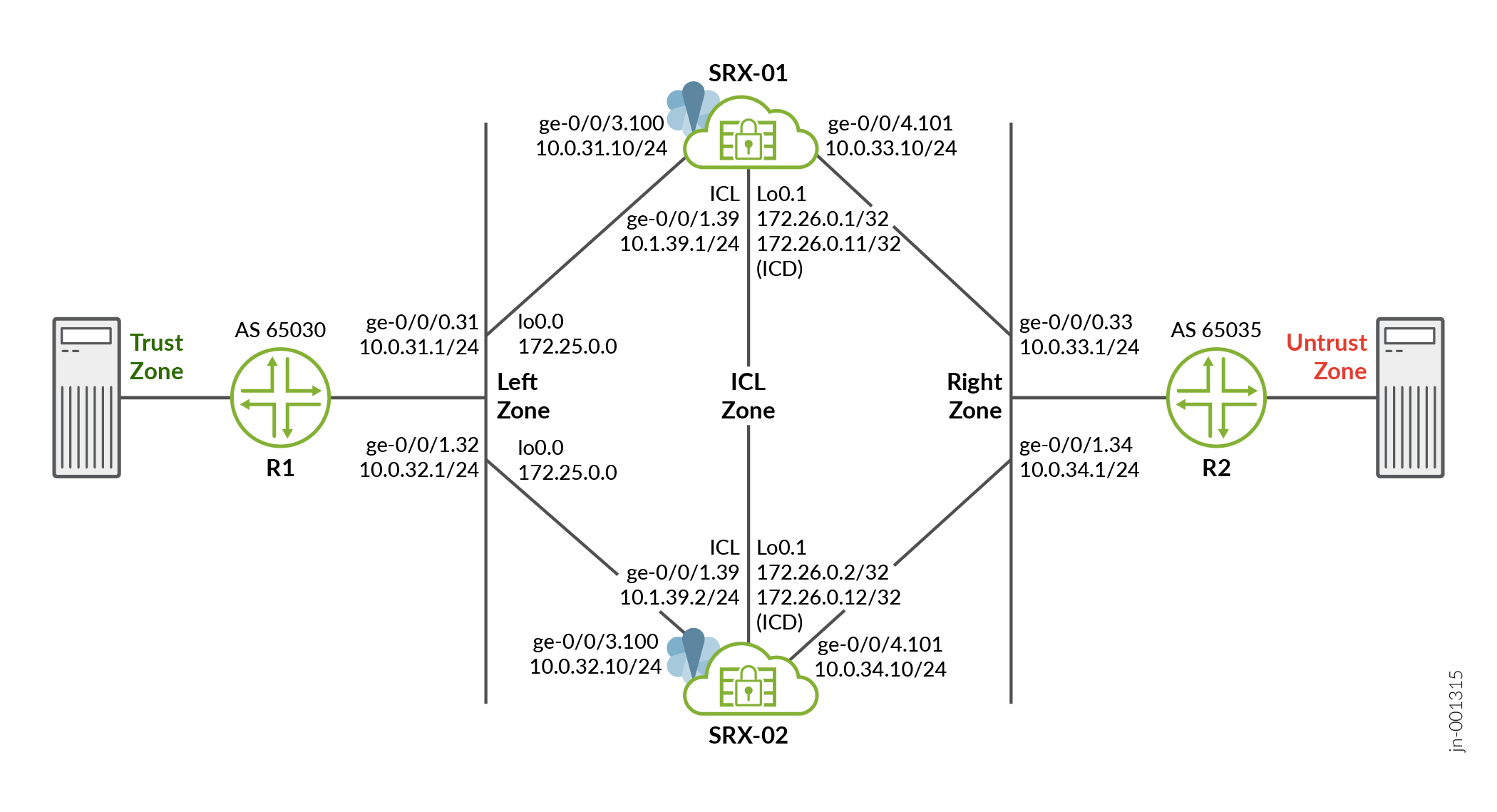
As shown in the topology, two SRX devices in MNHA are connected to adjacent routers (vSRX instances acting as routers). An encrypted logical interchassis link (ICL) connects the nodes. The nodes communicate with each other using a routable IP address (floating IP address) over the network. In this example, we've used GE ports for the ICL. We've also configured a routing instance for the ICL path to ensure maximum segmentation.
Loopback interfaces are used to host the IP addresses on firewalls and routers and the IP address on a loopback unit on each respective node is used for communication. In a typical high availability deployment, you have multiple routers and switches on the northbound and southbound sides of the network.
In this example, you'll create multiple configuration groups on devices and synchronize the configuration.
Topology Overview
Table 4 shows the details on interfaces configuration used in this example.
| Device | Interface | IP Address | Zone | Configured For |
|---|---|---|---|---|
| SRX-01 | lo0.1 | 172.26.0.11/32 | ICL Zone |
Local forwarding address used to forward data packet over ICD link. |
| lo0.1 | 172.26.0.1/32 | ICL Zone | ICL | |
| lo0.0 | 172.25.0.0/32 | Left Zone | Floating IP address | |
| ge-0/0/1.39 | 10.1.39.1/24 | ICL Zone | ICL to node 0 connection | |
|
|
|
Connects to upstream and downstream routers. | |
| SRX-02 | lo0.1 | 172.26.0.12/32 | ICL Zone |
Local forwarding address used to forward data packet over ICD link. |
| lo0.1 | 172.26.0.2/32 | ICL Zone | ICL | |
| lo0.0 | 172.25.0.0/32 | Left Zone | Floating IP address | |
| ge-0/0/1.39 | 10.1.39.2/24 | ICL Zone | ICL to node 0 connection | |
|
|
|
Connects to upstream and downstream routers. |
| Device | Interface | IP Address | Configured For |
|---|---|---|---|
| Router 1 (R1) | ge-0/0/0.31 | 10.0.31.1/24 | Connects to SRX-01 |
| ge-0/0/1.32 | 10.0.32.1/24 | Connects to SRX-02 | |
| Router 2 (R2) | ge-0/0/0.33 | 10.0.33.1/24 | Connects to SRX-01 |
| ge-0/0/1.34 | 10.0.34.1/24 | Connects to SRX-02 |
Configure Multinode High Availability Using Junos Group Statements
Verification
Use the following show commands to verify the feature in this example.
| Command | Verification Task |
|---|---|
|
show chassis high availability information |
Displays Multinode High Availability details including status. |
| show chassis high-availability peer-info |
Displays details such as peer node, connection details, and packet statistics of the peer node in a Multinode High Availability setup. |
| show chassis high-availability services-redundancy-group |
Display the service redundancy group information in a Multinode High Availability setup. |
- Check Multinode High Availability Details
- Check Multinode High Availability Peer Node Details
- Check Multinode High Availability Service Redundancy Group Details
Check Multinode High Availability Details
Purpose
View and verify the details of the Multinode High Availability setup configured on your security device.
Action
From operational mode, run the following commands on both nodes:
use@vsrx-mnha-n0> show chassis high-availability information
Node failure codes:
    HW  Hardware monitoring    LB  Loopback monitoring
    MB  Mbuf monitoring        SP  SPU monitoring
    CS  Cold Sync monitoring   SU  Software Upgrade

Node Status: ONLINE
Local-id: 1
Local-IP: 172.26.0.1
Local Forwarding IP: 172.26.0.11
HA Peer Information:

    Peer Id: 2        IP address: 172.26.0.2    Interface: lo0.1
    Routing Instance: icl
    Encrypted: YES

                  Conn State: UP
    Configured BFD Detection Time: 3 * 1000ms
    Cold Sync Status: COMPLETE
    Peer Forwarding IP: 172.26.0.12             Interface: lo0.1
    Peer ICD Conn State: UP

Services Redundancy Group: 0
        Current State: ONLINE
        Peer Information:
          Peer Id: 2

SRG failure event codes:
    BF  BFD monitoring
    IP  IP monitoring
    IF  Interface monitoring
    CP  Control Plane monitoring

Services Redundancy Group: 1
        Deployment Type: ROUTING
        Status: BACKUP
        Activeness Priority: 100
        Preemption: DISABLED
        Process Packet In Backup State: YES
        Control Plane State: READY
        System Integrity Check: COMPLETE
        Failure Events: NONE
        Peer Information:
          Peer Id: 2
          Status : ACTIVE
          Health Status: HEALTHY
          Failover Readiness: N/A
user@vsrx-mnha-n1# show chassis high-availability information
Node failure codes:
    HW  Hardware monitoring    LB  Loopback monitoring
    MB  Mbuf monitoring        SP  SPU monitoring
    CS  Cold Sync monitoring   SU  Software Upgrade

Node Status: ONLINE
Local-id: 2
Local-IP: 172.26.0.2
Local Forwarding IP: 172.26.0.12
HA Peer Information:

    Peer Id: 1        IP address: 172.26.0.1    Interface: lo0.1
    Routing Instance: icl
    Encrypted: YES

                  Conn State: UP
    Configured BFD Detection Time: 3 * 1000ms
    Cold Sync Status: COMPLETE
    Peer Forwarding IP: 172.26.0.11             Interface: lo0.1
    Peer ICD Conn State: UP

Services Redundancy Group: 0
        Current State: ONLINE
        Peer Information:
          Peer Id: 1

SRG failure event codes:
    BF  BFD monitoring
    IP  IP monitoring
    IF  Interface monitoring
    CP  Control Plane monitoring

Services Redundancy Group: 1
        Deployment Type: ROUTING
        Status: ACTIVE
        Activeness Priority: 200
        Preemption: DISABLED
        Process Packet In Backup State: YES
        Control Plane State: READY
        System Integrity Check: N/A
        Failure Events: NONE
        Peer Information:
          Peer Id: 1
          Status : BACKUP
          Health Status: HEALTHY
          Failover Readiness: READY
Meaning
Verify these details from the command output:
-
Local node and peer node details such as IP address and ID.
-
Node Status: ONLINEindicates that the node is up. -
Conn State: UPindicates that the ICL link is established and operational. -
Peer ICD Conn State: UPindicates that the ICD link is established and operational. -
Encrypted: YESindicates that ICL connection is encrypted. -
Peer InformationServices Redundancy Group indicates peer node is healthy and ready for failover.
Check Multinode High Availability Peer Node Details
Purpose
View details of the peer node in the Multinode High Availability setup.
Action
From operational mode, run the following command:
user@vsrx-mnha-n0> show chassis high-availability peer-info

HA Peer Information:

   Peer-ID: 2        IP address: 172.26.0.2    Interface: lo0.1
   Routing Instance: icl
   Encrypted: YES    Conn State: UP
   Cold Sync Status: COMPLETE
   Peer Forwarding IP: 172.26.0.12             Interface: lo0.1
   Peer ICD Conn State: UP
   Internal Interface: st0.16000
   Internal Local-IP: 180.100.1.1
   Internal Peer-IP: 180.100.1.2
   Internal Routing-instance: __juniper_private1__
Packet Statistics:
        Receive Error : 0        Send Error : 0

        Packet-type            Sent       Received
        SRG Status Msg           12              9
        SRG Status Ack            9              9
        Attribute Msg             7              4
        Attribute Ack             4              4
Meaning
You can get the following details from the command output:
-
Peer ID: 2shows the ID of the other node. -
Conn State: UPandPeer ICD Conn State: UPindicate that the both ICL and ICD link are established. -
Packet Statisticsshows packets transferred between the nodes.
Check Multinode High Availability Service Redundancy Group Details
Purpose
View and verify the details of the Multinode High Availability SRG details.
Action
From operational mode, run the following command:
SRX-01 Device
                  user@vsrx-mnha-n0> show chassis high-availability services-redundancy-group 1
SRG failure event codes:
    BF  BFD monitoring
    IP  IP monitoring
    IF  Interface monitoring
    CP  Control Plane monitoring

Services Redundancy Group: 1
        Deployment Type: ROUTING


                  Status: BACKUP
        Activeness Priority: 100
        Preemption: DISABLED
        Process Packet In Backup State: YES
        Control Plane State: READY
        System Integrity Check: COMPLETE
        Failure Events: NONE
        Peer Information:
        Peer Id: 2


                  Status : ACTIVE
          Health Status: HEALTHY
          Failover Readiness: N/A

        Signal Route Info:
          Active Signal Route:
          IP: 172.24.0.1
          Routing Instance: default
          Status: NOT INSTALLED

          Backup Signal Route:
          IP: 172.24.0.0
          Routing Instance: default
          Status: INSTALLED

        Split-brain Prevention Probe Info:
          DST-IP: 10.0.30.1
          SRC-IP: 172.25.0.0
          Routing Instance: vr
          Type: ICMP Probe
          Status: NOT RUNNING
          Result: N/A           Reason: N/A

        SRG Path Monitor Info:
          SRG Monitor Status: UP
          SRG Monitor Threshold: 200
          SRG Monitor Weight: 0
          SRG Monitor Failed Objects: NONE

          Object Name: routers
          Object Status: UP
          Object Monitored Entries: [ BFD ]
          Object Failures: [ BFD ]
          Object Threshold: 200
          Object Current Weight: 100

          Object Name: endpoints
          Object Status: UP
          Object Monitored Entries: [ IP ]
          Object Failures: [ IP ]
          Object Threshold: 200
          Object Current Weight: 100

IP SRGID Table:
        SRGID    IP Prefix                                   Routing Table
        1        172.25.0.0/32                               vr
Now run the same command on SRX-02 device and notice the command output differences such as Status, Peer Information and so on.
user@vsrx-mnha-n1> show chassis high-availability services-redundancy-group 1
SRG failure event codes:
    BF  BFD monitoring
    IP  IP monitoring
    IF  Interface monitoring
    CP  Control Plane monitoring

Services Redundancy Group: 1
        Deployment Type: ROUTING


                  Status: ACTIVE
        Activeness Priority: 200
        Preemption: DISABLED
        Process Packet In Backup State: YES
        Control Plane State: READY
        System Integrity Check: COMPLETE
        Failure Events: NONE
        Peer Information:
          Peer Id: 1


                  Status : BACKUP
          Health Status: HEALTHY
          Failover Readiness: READY

        Signal Route Info:
          Active Signal Route:
          IP: 172.24.0.1
          Routing Instance: default
          Status: INSTALLED

          Backup Signal Route:
          IP: 172.24.0.0
          Routing Instance: default
          Status: NOT INSTALLED

        Split-brain Prevention Probe Info:
          DST-IP: 10.0.30.1
          SRC-IP: 172.25.0.0
          Routing Instance: vr
          Type: ICMP Probe
          Status: NOT RUNNING
          Result: N/A           Reason: N/A


        SRG Path Monitor Info:
          SRG Monitor Status: UP
          SRG Monitor Threshold: 200
          SRG Monitor Weight: 0
          SRG Monitor Failed Objects: NONE

          Object Name: routers
          Object Status: UP
          Object Monitored Entries: [ BFD ]
          Object Failures: [ BFD ]
          Object Threshold: 200
          Object Current Weight: 100

          Object Name: endpoints
          Object Status: UP
          Object Monitored Entries: [ IP ]
          Object Failures: [ IP ]
          Object Threshold: 200
          Object Current Weight: 100

IP SRGID Table:
        SRGID    IP Prefix                                   Routing Table
        1        172.25.0.0/32                               vr
Meaning
Verify these details from the command output:
-
Deployment Type: ROUTINGindicates the Multinode High Availability is setup for Layer 3 (Routing) mode. -
Status: BACKUPindicates currently the node is operating as Backup node. -
Peer Informationprovides peer node details such as deployment type, status, and active and back up signal routes. -
The output also indicates configured monitoring options and failure events (if any).
Set Commands on All Devices
- Device Configured as Active Node (vsrx-mnha-n0)
- Device Configured as Backup Node (SRX-02)
- Router 1 (Device Configured as Router)
- Router 2 (Device Configured as Router)
Device Configured as Active Node (vsrx-mnha-n0)
set groups mnha-sync when peers vsrx-mnha-n0
set groups mnha-sync when peers vsrx-mnha-n1
set groups mnha-sync security ike proposal ike-prop authentication-method pre-shared-keys
set groups mnha-sync security ike proposal ike-prop dh-group group20
set groups mnha-sync security ike proposal ike-prop encryption-algorithm aes-256-gcm
set groups mnha-sync security ike proposal ike-prop lifetime-seconds 28800
set groups mnha-sync security ike policy ike-policy proposals ike-prop
set groups mnha-sync security ike policy ike-policy pre-shared-key ascii-text "$ABc123"
set groups mnha-sync security ike policy icl proposals ike-prop
set groups mnha-sync security ike gateway r1 ike-policy ike-policy
set groups mnha-sync security ike gateway r1 address 10.0.30.1
set groups mnha-sync security ike gateway r1 dead-peer-detection probe-idle-tunnel
set groups mnha-sync security ike gateway r1 dead-peer-detection interval 5
set groups mnha-sync security ike gateway r1 dead-peer-detection threshold 5
set groups mnha-sync security ike gateway r1 external-interface lo0.0
set groups mnha-sync security ike gateway r1 version v2-only
set groups mnha-sync security ike gateway icl ike-policy icl
set groups mnha-sync security ike gateway icl version v2-only
set groups mnha-sync security ipsec proposal ipsec-prop encryption-algorithm aes-256-gcm
set groups mnha-sync security ipsec proposal ipsec-prop lifetime-seconds 3600
set groups mnha-sync security ipsec policy ipsec-policy perfect-forward-secrecy keys group20
set groups mnha-sync security ipsec policy ipsec-policy proposals ipsec-prop
set groups mnha-sync security ipsec vpn r1 bind-interface st0.0
set groups mnha-sync security ipsec vpn r1 ike gateway r1
set groups mnha-sync security ipsec vpn r1 ike ipsec-policy ipsec-policy
set groups mnha-sync security ipsec vpn r1 traffic-selector ts1 local-ip 10.0.35.11/32
set groups mnha-sync security ipsec vpn r1 traffic-selector ts1 remote-ip 10.0.30.11/32
set groups mnha-sync security ipsec vpn r1 establish-tunnels immediately
set groups mnha-sync security ipsec vpn icl ha-link-encryption
set groups mnha-sync security ipsec vpn icl ike gateway icl
set groups mnha-sync security ipsec vpn icl ike ipsec-policy ipsec-policy
set groups mnha-sync security policies from-zone icl to-zone icl policy permit match source-address any
set groups mnha-sync security policies from-zone icl to-zone icl policy permit match destination-address any
set groups mnha-sync security policies from-zone icl to-zone icl policy permit match application any
set groups mnha-sync security policies from-zone icl to-zone icl policy permit then permit
set groups mnha-sync security policies global policy internal match source-address any
set groups mnha-sync security policies global policy internal match destination-address any
set groups mnha-sync security policies global policy internal match application any
set groups mnha-sync security policies global policy internal match from-zone right
set groups mnha-sync security policies global policy internal match from-zone vpn
set groups mnha-sync security policies global policy internal match from-zone left
set groups mnha-sync security policies global policy internal match to-zone left
set groups mnha-sync security policies global policy internal match to-zone right
set groups mnha-sync security policies global policy internal match to-zone vpn
set groups mnha-sync security policies global policy internal then permit
set groups mnha-sync security policies global policy internal then log session-close
set groups mnha-sync security policies global policy untrust match source-address any
set groups mnha-sync security policies global policy untrust match destination-address any
set groups mnha-sync security policies global policy untrust match application any
set groups mnha-sync security policies global policy untrust match from-zone left
set groups mnha-sync security policies global policy untrust match from-zone right
set groups mnha-sync security policies global policy untrust match to-zone untrust
set groups mnha-sync security policies global policy untrust then permit
set groups mnha-sync security zones security-zone vpn interfaces st0.0
set groups mnha-sync security zones security-zone left interfaces lo0.0 host-inbound-traffic system-services ike
set groups mnha-sync security zones security-zone left interfaces lo0.0 host-inbound-traffic system-services ping
set groups mnha-sync security zones security-zone left interfaces ge-0/0/3.100 host-inbound-traffic system-services ping
set groups mnha-sync security zones security-zone left interfaces ge-0/0/3.100 host-inbound-traffic protocols bgp
set groups mnha-sync security zones security-zone left interfaces ge-0/0/3.100 host-inbound-traffic protocols bfd
set groups mnha-sync security zones security-zone right interfaces ge-0/0/4.101 host-inbound-traffic system-services ping
set groups mnha-sync security zones security-zone right interfaces ge-0/0/4.101 host-inbound-traffic protocols bgp
set groups mnha-sync security zones security-zone right interfaces ge-0/0/4.101 host-inbound-traffic protocols bfd
set groups mnha-sync security zones security-zone untrust interfaces ge-0/0/0.102 host-inbound-traffic system-services ping
set groups mnha-sync security zones security-zone untrust interfaces ge-0/0/0.102 host-inbound-traffic protocols bfd
set groups mnha-sync security zones security-zone untrust interfaces ge-0/0/0.102 host-inbound-traffic protocols bgp
set groups mnha-sync interfaces st0 unit 0 family inet
set groups mnha-sync-icl system commit peers vsrx-mnha-n1 routing-instance icl
set groups mnha-sync-icl system static-host-mapping vsrx-mnha-n1 inet 172.26.0.2
set groups icd chassis high-availability local-id local-forwarding-ip 172.26.0.11
set groups icd chassis high-availability peer-id 2 peer-forwarding-ip 172.26.0.12
set groups icd chassis high-availability peer-id 2 peer-forwarding-ip interface lo0.1
set groups icd chassis high-availability peer-id 2 peer-forwarding-ip liveness-detection minimum-interval 1000
set groups icd chassis high-availability peer-id 2 peer-forwarding-ip liveness-detection multiplier 5
set groups icd interfaces lo0 unit 1 family inet address 172.26.0.11/32
set groups monitor-simple chassis high-availability services-redundancy-group 1 monitor bfd-liveliness 10.0.31.1 src-ip 10.0.31.10
set groups monitor-simple chassis high-availability services-redundancy-group 1 monitor bfd-liveliness 10.0.31.1 routing-instance vr
set groups monitor-simple chassis high-availability services-redundancy-group 1 monitor bfd-liveliness 10.0.31.1 session-type singlehop
set groups monitor-simple chassis high-availability services-redundancy-group 1 monitor bfd-liveliness 10.0.31.1 interface ge-0/0/0.100
set groups monitor-simple chassis high-availability services-redundancy-group 1 monitor bfd-liveliness 10.0.33.1 src-ip 10.0.33.10
set groups monitor-simple chassis high-availability services-redundancy-group 1 monitor bfd-liveliness 10.0.33.1 routing-instance vr
set groups monitor-simple chassis high-availability services-redundancy-group 1 monitor bfd-liveliness 10.0.33.1 session-type singlehop
set groups monitor-simple chassis high-availability services-redundancy-group 1 monitor bfd-liveliness 10.0.33.1 interface ge-0/0/0.101
set groups monitor-simple chassis high-availability services-redundancy-group 1 monitor bfd-liveliness 10.0.38.1 src-ip 10.0.38.10
set groups monitor-simple chassis high-availability services-redundancy-group 1 monitor bfd-liveliness 10.0.38.1 routing-instance vr
set groups monitor-simple chassis high-availability services-redundancy-group 1 monitor bfd-liveliness 10.0.38.1 session-type singlehop
set groups monitor-simple chassis high-availability services-redundancy-group 1 monitor bfd-liveliness 10.0.38.1 interface ge-0/0/0.102
set groups monitor-simple chassis high-availability services-redundancy-group 1 monitor interface ge-0/0/0
set groups monitor-advanced chassis high-availability services-redundancy-group 1 monitor monitor-object endpoints object-threshold 200
set groups monitor-advanced chassis high-availability services-redundancy-group 1 monitor monitor-object endpoints ip threshold 100
set groups monitor-advanced chassis high-availability services-redundancy-group 1 monitor monitor-object endpoints ip destination-ip 10.0.30.10 routing-instance vr
set groups monitor-advanced chassis high-availability services-redundancy-group 1 monitor monitor-object endpoints ip destination-ip 10.0.30.10 weight 50
set groups monitor-advanced chassis high-availability services-redundancy-group 1 monitor monitor-object endpoints ip destination-ip 10.0.35.10 routing-instance vr
set groups monitor-advanced chassis high-availability services-redundancy-group 1 monitor monitor-object endpoints ip destination-ip 10.0.35.10 weight 50
set groups monitor-advanced chassis high-availability services-redundancy-group 1 monitor monitor-object routers object-threshold 200
set groups monitor-advanced chassis high-availability services-redundancy-group 1 monitor monitor-object routers bfd-liveliness threshold 100
set groups monitor-advanced chassis high-availability services-redundancy-group 1 monitor monitor-object routers bfd-liveliness destination-ip 10.0.31.1 src-ip 10.0.31.10
set groups monitor-advanced chassis high-availability services-redundancy-group 1 monitor monitor-object routers bfd-liveliness destination-ip 10.0.31.1 routing-instance vr
set groups monitor-advanced chassis high-availability services-redundancy-group 1 monitor monitor-object routers bfd-liveliness destination-ip 10.0.31.1 session-type singlehop
set groups monitor-advanced chassis high-availability services-redundancy-group 1 monitor monitor-object routers bfd-liveliness destination-ip 10.0.31.1 interface ge-0/0/3.100
set groups monitor-advanced chassis high-availability services-redundancy-group 1 monitor monitor-object routers bfd-liveliness destination-ip 10.0.31.1 weight 100
set groups monitor-advanced chassis high-availability services-redundancy-group 1 monitor monitor-object routers bfd-liveliness destination-ip 10.0.33.1 src-ip 10.0.33.10
set groups monitor-advanced chassis high-availability services-redundancy-group 1 monitor monitor-object routers bfd-liveliness destination-ip 10.0.33.1 routing-instance vr
set groups monitor-advanced chassis high-availability services-redundancy-group 1 monitor monitor-object routers bfd-liveliness destination-ip 10.0.33.1 session-type singlehop
set groups monitor-advanced chassis high-availability services-redundancy-group 1 monitor monitor-object routers bfd-liveliness destination-ip 10.0.33.1 interface ge-0/0/4.101
set groups monitor-advanced chassis high-availability services-redundancy-group 1 monitor monitor-object routers bfd-liveliness destination-ip 10.0.33.1 weight 100
set groups monitor-advanced chassis high-availability services-redundancy-group 1 monitor monitor-object routers bfd-liveliness destination-ip 10.0.38.1 src-ip 10.0.38.10
set groups monitor-advanced chassis high-availability services-redundancy-group 1 monitor monitor-object routers bfd-liveliness destination-ip 10.0.38.1 routing-instance vr
set groups monitor-advanced chassis high-availability services-redundancy-group 1 monitor monitor-object routers bfd-liveliness destination-ip 10.0.38.1 session-type singlehop
set groups monitor-advanced chassis high-availability services-redundancy-group 1 monitor monitor-object routers bfd-liveliness destination-ip 10.0.38.1 interface ge-0/0/0.102
set groups monitor-advanced chassis high-availability services-redundancy-group 1 monitor monitor-object routers bfd-liveliness destination-ip 10.0.38.1 weight 100
set groups monitor-advanced chassis high-availability services-redundancy-group 1 monitor srg-threshold 200
set apply-groups mnha-sync
set apply-groups mnha-sync-icl
set apply-groups monitor-advanced
set apply-groups icd
set system commit peers vsrx-mnha-n1 user user
set system commit peers vsrx-mnha-n1 authentication "$ABC123"
set chassis high-availability local-id 1
set chassis high-availability local-id local-ip 172.26.0.1
set chassis high-availability peer-id 2 peer-ip 172.26.0.2
set chassis high-availability peer-id 2 interface lo0.1
set chassis high-availability peer-id 2 routing-instance icl
set chassis high-availability peer-id 2 vpn-profile icl
set chassis high-availability peer-id 2 liveness-detection minimum-interval 1000
set chassis high-availability peer-id 2 liveness-detection multiplier 3
set chassis high-availability services-redundancy-group 0 peer-id 2
set chassis high-availability services-redundancy-group 1 deployment-type routing
set chassis high-availability services-redundancy-group 1 peer-id 2
set chassis high-availability services-redundancy-group 1 activeness-probe dest-ip 10.0.30.1
set chassis high-availability services-redundancy-group 1 activeness-probe dest-ip src-ip 172.25.0.0
set chassis high-availability services-redundancy-group 1 activeness-probe dest-ip routing-instance vr
set chassis high-availability services-redundancy-group 1 active-signal-route 172.24.0.1
set chassis high-availability services-redundancy-group 1 backup-signal-route 172.24.0.0
set chassis high-availability services-redundancy-group 1 prefix-list srg1-prefix routing-instance vr
set chassis high-availability services-redundancy-group 1 managed-services ipsec
set chassis high-availability services-redundancy-group 1 process-packet-on-backup
set chassis high-availability services-redundancy-group 1 activeness-priority 100
set security ike proposal ike-prop authentication-method pre-shared-keys
set security ike proposal ike-prop dh-group group20
set security ike proposal ike-prop encryption-algorithm aes-256-gcm
set security ike proposal ike-prop lifetime-seconds 28800
set security ike policy ike-policy proposals ike-prop
set security ike policy ike-policy pre-shared-key ascii-text "$ABC123"
set security ike policy icl proposals ike-prop
set security ike policy icl pre-shared-key ascii-text "$ABC123."
set security ike gateway icl ike-policy icl
set security ike gateway icl version v2-only
set security ipsec proposal ipsec-prop encryption-algorithm aes-256-gcm
set security ipsec proposal ipsec-prop lifetime-seconds 3600
set security ipsec policy ipsec-policy perfect-forward-secrecy keys group20
set security ipsec policy ipsec-policy proposals ipsec-prop
set security ipsec vpn icl ha-link-encryption
set security ipsec vpn icl ike gateway icl
set security ipsec vpn icl ike ipsec-policy ipsec-policy
set security zones security-zone icl interfaces ge-0/0/3.36 host-inbound-traffic system-services ping
set security zones security-zone icl interfaces ge-0/0/3.36 host-inbound-traffic protocols bgp
set security zones security-zone icl interfaces ge-0/0/3.36 host-inbound-traffic protocols bfd
set security zones security-zone icl interfaces lo0.1 host-inbound-traffic system-services ping
set security zones security-zone icl interfaces lo0.1 host-inbound-traffic system-services ike
set security zones security-zone icl interfaces lo0.1 host-inbound-traffic system-services high-availability
set security zones security-zone icl interfaces lo0.1 host-inbound-traffic system-services ssh
set security zones security-zone icl interfaces lo0.1 host-inbound-traffic protocols bfd
set security zones security-zone icl interfaces ge-0/0/1.39 host-inbound-traffic system-services ping
set security zones security-zone icl interfaces ge-0/0/1.39 host-inbound-traffic protocols bgp
set security zones security-zone icl interfaces ge-0/0/1.39 host-inbound-traffic protocols bfd
set interfaces ge-0/0/0 description for-monitoring
set interfaces ge-0/0/0 vlan-tagging
set interfaces ge-0/0/0 unit 102 description vr-uplink-r2
set interfaces ge-0/0/0 unit 102 vlan-id 38
set interfaces ge-0/0/0 unit 102 family inet address 10.0.38.10/24
set interfaces ge-0/0/1 description br-lab-ha-1
set interfaces ge-0/0/1 vlan-tagging
set interfaces ge-0/0/1 mtu 9000
set interfaces ge-0/0/1 unit 39 description icl-n1
set interfaces ge-0/0/1 unit 39 vlan-id 39
set interfaces ge-0/0/1 unit 39 family inet address 10.1.39.1/24
set interfaces ge-0/0/3 vlan-tagging
set interfaces ge-0/0/3 unit 36 description icl-r1
set interfaces ge-0/0/3 unit 36 vlan-id 36
set interfaces ge-0/0/3 unit 36 family inet address 10.0.36.10/24
set interfaces ge-0/0/3 unit 100 description vr-left-r1
set interfaces ge-0/0/3 unit 100 vlan-id 31
set interfaces ge-0/0/3 unit 100 family inet address 10.0.31.10/24
set interfaces ge-0/0/4 vlan-tagging
set interfaces ge-0/0/4 unit 101 description vr-right-r2
set interfaces ge-0/0/4 unit 101 vlan-id 33
set interfaces ge-0/0/4 unit 101 family inet address 10.0.33.10/24
set interfaces lo0 unit 0 description "Floating IP"
set interfaces lo0 unit 0 family inet address 172.25.0.0/32
set interfaces lo0 unit 1 description ICL
set interfaces lo0 unit 1 family inet address 172.26.0.1/32
set policy-options prefix-list export-int 0.0.0.0/0
set policy-options prefix-list export-int 172.25.0.0/32
set policy-options prefix-list export-uplink 10.0.30.0/24
set policy-options prefix-list export-uplink 10.0.35.0/24
set policy-options prefix-list srg1-prefix 172.25.0.0/32
set policy-options policy-statement export-icl-r1 term 10 from interface lo0.1
set policy-options policy-statement export-icl-r1 term 10 then accept
set policy-options policy-statement export-icl-r1 term 100 then reject
set policy-options policy-statement export-icl-to-n1 term 10 from interface lo0.1
set policy-options policy-statement export-icl-to-n1 term 10 then accept
set policy-options policy-statement export-icl-to-n1 term 100 then reject
set policy-options policy-statement export-to-int term 10 from prefix-list export-int
set policy-options policy-statement export-to-int term 10 from condition srg1_backup
set policy-options policy-statement export-to-int term 10 then as-path-prepend 65031
set policy-options policy-statement export-to-int term 10 then accept
set policy-options policy-statement export-to-int term 20 from prefix-list export-int
set policy-options policy-statement export-to-int term 20 from condition srg1_active
set policy-options policy-statement export-to-int term 20 then accept
set policy-options policy-statement export-to-int term 90 from prefix-list export-int
set policy-options policy-statement export-to-int term 90 then as-path-prepend "65031 65031"
set policy-options policy-statement export-to-int term 90 then accept
set policy-options policy-statement export-to-int term 100 then reject
set policy-options policy-statement export-to-uplink term 10 from prefix-list export-uplink
set policy-options policy-statement export-to-uplink term 10 from condition srg1_backup
set policy-options policy-statement export-to-uplink term 10 then as-path-prepend 65031
set policy-options policy-statement export-to-uplink term 10 then accept
set policy-options policy-statement export-to-uplink term 20 from prefix-list export-uplink
set policy-options policy-statement export-to-uplink term 20 from condition srg1_active
set policy-options policy-statement export-to-uplink term 20 then accept
set policy-options policy-statement export-to-uplink term 90 from prefix-list export-uplink
set policy-options policy-statement export-to-uplink term 90 then as-path-prepend "65031 65031"
set policy-options policy-statement export-to-uplink term 90 then accept
set policy-options policy-statement export-to-uplink term 100 then reject
set policy-options condition srg1_active if-route-exists 172.24.0.1/32
set policy-options condition srg1_active if-route-exists table inet.0
set policy-options condition srg1_backup if-route-exists 172.24.0.0/32
set policy-options condition srg1_backup if-route-exists table inet.0
set routing-instances icl instance-type virtual-router
set routing-instances icl protocols bgp group icl neighbor 10.0.36.1 export export-icl-r1
set routing-instances icl protocols bgp group icl neighbor 10.0.36.1 peer-as 65030
set routing-instances icl protocols bgp group icl neighbor 10.1.39.2 export export-icl-to-n1
set routing-instances icl protocols bgp group icl neighbor 10.1.39.2 peer-as 65032
set routing-instances icl protocols bgp local-as 65031
set routing-instances icl protocols bgp bfd-liveness-detection minimum-interval 500
set routing-instances icl protocols bgp bfd-liveness-detection multiplier 3
set routing-instances icl interface ge-0/0/1.39
set routing-instances icl interface ge-0/0/3.36
set routing-instances icl interface lo0.1
set routing-instances vr instance-type virtual-router
set routing-instances vr protocols bgp group r1 neighbor 10.0.31.1 export export-to-int
set routing-instances vr protocols bgp group r1 neighbor 10.0.31.1 peer-as 65030
set routing-instances vr protocols bgp group r2 neighbor 10.0.33.1 export export-to-int
set routing-instances vr protocols bgp group r2 neighbor 10.0.33.1 peer-as 65035
set routing-instances vr protocols bgp group uplink-r2 neighbor 10.0.38.1 export export-to-uplink
set routing-instances vr protocols bgp group uplink-r2 neighbor 10.0.38.1 peer-as 65039
set routing-instances vr protocols bgp local-as 65031
set routing-instances vr protocols bgp bfd-liveness-detection minimum-interval 1000
set routing-instances vr protocols bgp bfd-liveness-detection multiplier 3
set routing-instances vr interface ge-0/0/0.102
set routing-instances vr interface ge-0/0/3.100
set routing-instances vr interface ge-0/0/4.101
set routing-instances vr interface lo0.0
Device Configured as Backup Node (SRX-02)
set groups mnha-sync-icl system commit peers vsrx-mnha-n0 routing-instance icl
set groups mnha-sync-icl system static-host-mapping vsrx-mnha-n0 inet 172.26.0.1
set groups mnha-sync when peers vsrx-mnha-n0
set groups mnha-sync when peers vsrx-mnha-n1
set groups mnha-sync security ike proposal ike-prop authentication-method pre-shared-keys
set groups mnha-sync security ike proposal ike-prop dh-group group20
set groups mnha-sync security ike proposal ike-prop encryption-algorithm aes-256-gcm
set groups mnha-sync security ike proposal ike-prop lifetime-seconds 28800
set groups mnha-sync security ike policy ike-policy proposals ike-prop
set groups mnha-sync security ike policy ike-policy pre-shared-key ascii-text "$ABC123"
set groups mnha-sync security ike policy icl proposals ike-prop
set groups mnha-sync security ike gateway r1 ike-policy ike-policy
set groups mnha-sync security ike gateway r1 address 10.0.30.1
set groups mnha-sync security ike gateway r1 dead-peer-detection probe-idle-tunnel
set groups mnha-sync security ike gateway r1 dead-peer-detection interval 5
set groups mnha-sync security ike gateway r1 dead-peer-detection threshold 5
set groups mnha-sync security ike gateway r1 external-interface lo0.0
set groups mnha-sync security ike gateway r1 version v2-only
set groups mnha-sync security ike gateway icl ike-policy icl
set groups mnha-sync security ike gateway icl version v2-only
set groups mnha-sync security ipsec proposal ipsec-prop encryption-algorithm aes-256-gcm
set groups mnha-sync security ipsec proposal ipsec-prop lifetime-seconds 3600
set groups mnha-sync security ipsec policy ipsec-policy perfect-forward-secrecy keys group20
set groups mnha-sync security ipsec policy ipsec-policy proposals ipsec-prop
set groups mnha-sync security ipsec vpn r1 bind-interface st0.0
set groups mnha-sync security ipsec vpn r1 ike gateway r1
set groups mnha-sync security ipsec vpn r1 ike ipsec-policy ipsec-policy
set groups mnha-sync security ipsec vpn r1 traffic-selector ts1 local-ip 10.0.35.11/32
set groups mnha-sync security ipsec vpn r1 traffic-selector ts1 remote-ip 10.0.30.11/32
set groups mnha-sync security ipsec vpn r1 establish-tunnels immediately
set groups mnha-sync security ipsec vpn icl ha-link-encryption
set groups mnha-sync security ipsec vpn icl ike gateway icl
set groups mnha-sync security ipsec vpn icl ike ipsec-policy ipsec-policy
set groups mnha-sync security flow tcp-mss ipsec-vpn mss 1400
set groups mnha-sync security flow tcp-session strict-syn-check
set groups mnha-sync security policies from-zone icl to-zone icl policy permit match source-address any
set groups mnha-sync security policies from-zone icl to-zone icl policy permit match destination-address any
set groups mnha-sync security policies from-zone icl to-zone icl policy permit match application any
set groups mnha-sync security policies from-zone icl to-zone icl policy permit then permit
set groups mnha-sync security policies global policy internal match source-address any
set groups mnha-sync security policies global policy internal match destination-address any
set groups mnha-sync security policies global policy internal match application any
set groups mnha-sync security policies global policy internal match from-zone right
set groups mnha-sync security policies global policy internal match from-zone vpn
set groups mnha-sync security policies global policy internal match from-zone left
set groups mnha-sync security policies global policy internal match to-zone left
set groups mnha-sync security policies global policy internal match to-zone right
set groups mnha-sync security policies global policy internal match to-zone vpn
set groups mnha-sync security policies global policy internal then permit
set groups mnha-sync security policies global policy internal then log session-close
set groups mnha-sync security policies global policy untrust match source-address any
set groups mnha-sync security policies global policy untrust match destination-address any
set groups mnha-sync security policies global policy untrust match application any
set groups mnha-sync security policies global policy untrust match from-zone left
set groups mnha-sync security policies global policy untrust match from-zone right
set groups mnha-sync security policies global policy untrust match to-zone untrust
set groups mnha-sync security policies global policy untrust then permit
set groups mnha-sync security zones security-zone vpn interfaces st0.0
set groups mnha-sync security zones security-zone left interfaces lo0.0 host-inbound-traffic system-services ike
set groups mnha-sync security zones security-zone left interfaces lo0.0 host-inbound-traffic system-services ping
set groups mnha-sync security zones security-zone left interfaces ge-0/0/3.100 host-inbound-traffic system-services ping
set groups mnha-sync security zones security-zone left interfaces ge-0/0/3.100 host-inbound-traffic protocols bgp
set groups mnha-sync security zones security-zone left interfaces ge-0/0/3.100 host-inbound-traffic protocols bfd
set groups mnha-sync security zones security-zone right interfaces ge-0/0/4.101 host-inbound-traffic system-services ping
set groups mnha-sync security zones security-zone right interfaces ge-0/0/4.101 host-inbound-traffic protocols bgp
set groups mnha-sync security zones security-zone right interfaces ge-0/0/4.101 host-inbound-traffic protocols bfd
set groups mnha-sync security zones security-zone untrust interfaces ge-0/0/0.102 host-inbound-traffic system-services ping
set groups mnha-sync security zones security-zone untrust interfaces ge-0/0/0.102 host-inbound-traffic protocols bfd
set groups mnha-sync security zones security-zone untrust interfaces ge-0/0/0.102 host-inbound-traffic protocols bgp
set groups mnha-sync interfaces st0 unit 0 family inet
set groups icd chassis high-availability local-id local-forwarding-ip 172.26.0.12
set groups icd chassis high-availability peer-id 1 peer-forwarding-ip 172.26.0.11
set groups icd chassis high-availability peer-id 1 peer-forwarding-ip interface lo0.1
set groups icd chassis high-availability peer-id 1 peer-forwarding-ip liveness-detection minimum-interval 1000
set groups icd chassis high-availability peer-id 1 peer-forwarding-ip liveness-detection multiplier 5
set groups icd interfaces lo0 unit 1 family inet address 172.26.0.12/32
set groups monitor-simple chassis high-availability services-redundancy-group 1 monitor bfd-liveliness 10.0.32.1 src-ip 10.0.32.10
set groups monitor-simple chassis high-availability services-redundancy-group 1 monitor bfd-liveliness 10.0.32.1 routing-instance vr
set groups monitor-simple chassis high-availability services-redundancy-group 1 monitor bfd-liveliness 10.0.32.1 session-type singlehop
set groups monitor-simple chassis high-availability services-redundancy-group 1 monitor bfd-liveliness 10.0.32.1 interface ge-0/0/3.100
set groups monitor-simple chassis high-availability services-redundancy-group 1 monitor bfd-liveliness 10.0.34.1 src-ip 10.0.34.10
set groups monitor-simple chassis high-availability services-redundancy-group 1 monitor bfd-liveliness 10.0.34.1 routing-instance vr
set groups monitor-simple chassis high-availability services-redundancy-group 1 monitor bfd-liveliness 10.0.34.1 session-type singlehop
set groups monitor-simple chassis high-availability services-redundancy-group 1 monitor bfd-liveliness 10.0.34.1 interface ge-0/0/4.101
set groups monitor-simple chassis high-availability services-redundancy-group 1 monitor bfd-liveliness 10.0.39.1 src-ip 10.0.39.10
set groups monitor-simple chassis high-availability services-redundancy-group 1 monitor bfd-liveliness 10.0.39.1 routing-instance vr
set groups monitor-simple chassis high-availability services-redundancy-group 1 monitor bfd-liveliness 10.0.39.1 session-type singlehop
set groups monitor-simple chassis high-availability services-redundancy-group 1 monitor bfd-liveliness 10.0.39.1 interface ge-0/0/0.102
set groups monitor-simple chassis high-availability services-redundancy-group 1 monitor interface ge-0/0/0
set groups monitor-advanced chassis high-availability services-redundancy-group 1 monitor monitor-object endpoints object-threshold 200
set groups monitor-advanced chassis high-availability services-redundancy-group 1 monitor monitor-object endpoints ip threshold 100
set groups monitor-advanced chassis high-availability services-redundancy-group 1 monitor monitor-object endpoints ip destination-ip 10.0.30.10 routing-instance vr
set groups monitor-advanced chassis high-availability services-redundancy-group 1 monitor monitor-object endpoints ip destination-ip 10.0.30.10 weight 50
set groups monitor-advanced chassis high-availability services-redundancy-group 1 monitor monitor-object endpoints ip destination-ip 10.0.35.10 routing-instance vr
set groups monitor-advanced chassis high-availability services-redundancy-group 1 monitor monitor-object endpoints ip destination-ip 10.0.35.10 weight 50
set groups monitor-advanced chassis high-availability services-redundancy-group 1 monitor monitor-object routers object-threshold 200
set groups monitor-advanced chassis high-availability services-redundancy-group 1 monitor monitor-object routers bfd-liveliness threshold 100
set groups monitor-advanced chassis high-availability services-redundancy-group 1 monitor monitor-object routers bfd-liveliness destination-ip 10.0.32.1 src-ip 10.0.32.10
set groups monitor-advanced chassis high-availability services-redundancy-group 1 monitor monitor-object routers bfd-liveliness destination-ip 10.0.32.1 routing-instance vr
set groups monitor-advanced chassis high-availability services-redundancy-group 1 monitor monitor-object routers bfd-liveliness destination-ip 10.0.32.1 session-type singlehop
set groups monitor-advanced chassis high-availability services-redundancy-group 1 monitor monitor-object routers bfd-liveliness destination-ip 10.0.32.1 interface ge-0/0/3.100
set groups monitor-advanced chassis high-availability services-redundancy-group 1 monitor monitor-object routers bfd-liveliness destination-ip 10.0.32.1 weight 100
set groups monitor-advanced chassis high-availability services-redundancy-group 1 monitor monitor-object routers bfd-liveliness destination-ip 10.0.34.1 src-ip 10.0.34.10
set groups monitor-advanced chassis high-availability services-redundancy-group 1 monitor monitor-object routers bfd-liveliness destination-ip 10.0.34.1 routing-instance vr
set groups monitor-advanced chassis high-availability services-redundancy-group 1 monitor monitor-object routers bfd-liveliness destination-ip 10.0.34.1 session-type singlehop
set groups monitor-advanced chassis high-availability services-redundancy-group 1 monitor monitor-object routers bfd-liveliness destination-ip 10.0.34.1 interface ge-0/0/4.101
set groups monitor-advanced chassis high-availability services-redundancy-group 1 monitor monitor-object routers bfd-liveliness destination-ip 10.0.34.1 weight 100
set groups monitor-advanced chassis high-availability services-redundancy-group 1 monitor monitor-object routers bfd-liveliness destination-ip 10.0.39.1 src-ip 10.0.39.10
set groups monitor-advanced chassis high-availability services-redundancy-group 1 monitor monitor-object routers bfd-liveliness destination-ip 10.0.39.1 routing-instance vr
set groups monitor-advanced chassis high-availability services-redundancy-group 1 monitor monitor-object routers bfd-liveliness destination-ip 10.0.39.1 session-type singlehop
set groups monitor-advanced chassis high-availability services-redundancy-group 1 monitor monitor-object routers bfd-liveliness destination-ip 10.0.39.1 interface ge-0/0/0.102
set groups monitor-advanced chassis high-availability services-redundancy-group 1 monitor monitor-object routers bfd-liveliness destination-ip 10.0.39.1 weight 100
set groups monitor-advanced chassis high-availability services-redundancy-group 1 monitor srg-threshold 200
set apply-groups mnha-sync
set apply-groups mnha-sync-icl
set apply-groups monitor-advanced
set apply-groups icd
set system commit peers vsrx-mnha-n0 user user
set system commit peers vsrx-mnha-n0 authentication "$ABC123"
set chassis high-availability local-id 2
set chassis high-availability local-id local-ip 172.26.0.2
set chassis high-availability peer-id 1 peer-ip 172.26.0.1
set chassis high-availability peer-id 1 interface lo0.1
set chassis high-availability peer-id 1 routing-instance icl
set chassis high-availability peer-id 1 vpn-profile icl
set chassis high-availability peer-id 1 liveness-detection minimum-interval 1000
set chassis high-availability peer-id 1 liveness-detection multiplier 3
set chassis high-availability services-redundancy-group 0 peer-id 1
set chassis high-availability services-redundancy-group 1 deployment-type routing
set chassis high-availability services-redundancy-group 1 peer-id 1
set chassis high-availability services-redundancy-group 1 activeness-probe dest-ip 10.0.30.1
set chassis high-availability services-redundancy-group 1 activeness-probe dest-ip src-ip 172.25.0.0
set chassis high-availability services-redundancy-group 1 activeness-probe dest-ip routing-instance vr
set chassis high-availability services-redundancy-group 1 active-signal-route 172.24.0.1
set chassis high-availability services-redundancy-group 1 backup-signal-route 172.24.0.0
set chassis high-availability services-redundancy-group 1 prefix-list srg1-prefix routing-instance vr
set chassis high-availability services-redundancy-group 1 managed-services ipsec
set chassis high-availability services-redundancy-group 1 process-packet-on-backup
set chassis high-availability services-redundancy-group 1 activeness-priority 200
set security ike proposal ike-prop authentication-method pre-shared-keys
set security ike proposal ike-prop dh-group group20
set security ike proposal ike-prop encryption-algorithm aes-256-gcm
set security ike proposal ike-prop lifetime-seconds 28800
set security ike policy ike-policy proposals ike-prop
set security ike policy ike-policy pre-shared-key ascii-text "$ABC123"
set security ike policy icl proposals ike-prop
set security ike policy icl pre-shared-key ascii-text "$ABC123"
set security ike gateway icl ike-policy icl
set security ike gateway icl version v2-only
set security ipsec proposal ipsec-prop encryption-algorithm aes-256-gcm
set security ipsec proposal ipsec-prop lifetime-seconds 3600
set security ipsec policy ipsec-policy perfect-forward-secrecy keys group20
set security ipsec policy ipsec-policy proposals ipsec-prop
set security ipsec vpn icl ha-link-encryption
set security ipsec vpn icl ike gateway icl
set security ipsec vpn icl ike ipsec-policy ipsec-policy
set security zones security-zone icl interfaces ge-0/0/3.37 host-inbound-traffic system-services ping
set security zones security-zone icl interfaces ge-0/0/3.37 host-inbound-traffic protocols bgp
set security zones security-zone icl interfaces ge-0/0/3.37 host-inbound-traffic protocols bfd
set security zones security-zone icl interfaces lo0.1 host-inbound-traffic system-services ping
set security zones security-zone icl interfaces lo0.1 host-inbound-traffic system-services ike
set security zones security-zone icl interfaces lo0.1 host-inbound-traffic system-services high-availability
set security zones security-zone icl interfaces lo0.1 host-inbound-traffic system-services ssh
set security zones security-zone icl interfaces lo0.1 host-inbound-traffic protocols bfd
set security zones security-zone icl interfaces ge-0/0/1.39 host-inbound-traffic system-services ping
set security zones security-zone icl interfaces ge-0/0/1.39 host-inbound-traffic protocols bgp
set security zones security-zone icl interfaces ge-0/0/1.39 host-inbound-traffic protocols bfd
set interfaces ge-0/0/0 description for-monitoring
set interfaces ge-0/0/0 vlan-tagging
set interfaces ge-0/0/0 unit 102 description vr-uplink-r2
set interfaces ge-0/0/0 unit 102 vlan-id 39
set interfaces ge-0/0/0 unit 102 family inet address 10.0.39.10/24
set interfaces ge-0/0/1 description br-lab-ha-1
set interfaces ge-0/0/1 vlan-tagging
set interfaces ge-0/0/1 mtu 9000
set interfaces ge-0/0/1 unit 39 description icl-n0
set interfaces ge-0/0/1 unit 39 vlan-id 39
set interfaces ge-0/0/1 unit 39 family inet address 10.1.39.2/24
set interfaces ge-0/0/3 vlan-tagging
set interfaces ge-0/0/3 unit 37 description icl-r1
set interfaces ge-0/0/3 unit 37 vlan-id 37
set interfaces ge-0/0/3 unit 37 family inet address 10.0.37.10/24
set interfaces ge-0/0/3 unit 100 description vr-left-r1
set interfaces ge-0/0/3 unit 100 vlan-id 32
set interfaces ge-0/0/3 unit 100 family inet address 10.0.32.10/24
set interfaces ge-0/0/4 vlan-tagging
set interfaces ge-0/0/4 unit 101 description vr-right-r2
set interfaces ge-0/0/4 unit 101 vlan-id 34
set interfaces ge-0/0/4 unit 101 family inet address 10.0.34.10/24
set interfaces lo0 unit 0 description "Floating IP"
set interfaces lo0 unit 0 family inet address 172.25.0.0/32
set interfaces lo0 unit 1 description ICL
set interfaces lo0 unit 1 family inet address 172.26.0.2/32
set policy-options prefix-list export-int 0.0.0.0/0
set policy-options prefix-list export-int 172.25.0.0/32
set policy-options prefix-list export-uplink 10.0.30.0/24
set policy-options prefix-list export-uplink 10.0.35.0/24
set policy-options prefix-list srg1-prefix 172.25.0.0/32
set policy-options policy-statement export-icl-r1 term 10 from interface lo0.1
set policy-options policy-statement export-icl-r1 term 10 then accept
set policy-options policy-statement export-icl-r1 term 100 then reject
set policy-options policy-statement export-icl-to-n0 term 10 from interface lo0.1
set policy-options policy-statement export-icl-to-n0 term 10 then accept
set policy-options policy-statement export-icl-to-n0 term 100 then reject
set policy-options policy-statement export-to-int term 10 from prefix-list export-int
set policy-options policy-statement export-to-int term 10 from condition srg1_backup
set policy-options policy-statement export-to-int term 10 then as-path-prepend 65032
set policy-options policy-statement export-to-int term 10 then accept
set policy-options policy-statement export-to-int term 20 from prefix-list export-int
set policy-options policy-statement export-to-int term 20 from condition srg1_active
set policy-options policy-statement export-to-int term 20 then accept
set policy-options policy-statement export-to-int term 90 from prefix-list export-int
set policy-options policy-statement export-to-int term 90 then as-path-prepend "65032 65032 65032"
set policy-options policy-statement export-to-int term 90 then accept
set policy-options policy-statement export-to-int term 100 then reject
set policy-options policy-statement export-to-uplink term 10 from prefix-list export-uplink
set policy-options policy-statement export-to-uplink term 10 from condition srg1_backup
set policy-options policy-statement export-to-uplink term 10 then as-path-prepend 65032
set policy-options policy-statement export-to-uplink term 10 then accept
set policy-options policy-statement export-to-uplink term 20 from prefix-list export-uplink
set policy-options policy-statement export-to-uplink term 20 from condition srg1_active
set policy-options policy-statement export-to-uplink term 20 then accept
set policy-options policy-statement export-to-uplink term 90 from prefix-list export-uplink
set policy-options policy-statement export-to-uplink term 90 then as-path-prepend "65032 65032 65032"
set policy-options policy-statement export-to-uplink term 90 then accept
set policy-options policy-statement export-to-uplink term 100 then reject
set policy-options condition srg1_active if-route-exists 172.24.0.1/32
set policy-options condition srg1_active if-route-exists table inet.0
set policy-options condition srg1_backup if-route-exists 172.24.0.0/32
set policy-options condition srg1_backup if-route-exists table inet.0
set routing-instances icl instance-type virtual-router
set routing-instances icl protocols bgp group icl neighbor 10.0.37.1 export export-icl-r1
set routing-instances icl protocols bgp group icl neighbor 10.0.37.1 peer-as 65030
set routing-instances icl protocols bgp group icl neighbor 10.1.39.1 export export-icl-to-n0
set routing-instances icl protocols bgp group icl neighbor 10.1.39.1 peer-as 65031
set routing-instances icl protocols bgp local-as 65032
set routing-instances icl protocols bgp bfd-liveness-detection minimum-interval 500
set routing-instances icl protocols bgp bfd-liveness-detection multiplier 3
set routing-instances icl interface ge-0/0/1.39
set routing-instances icl interface ge-0/0/3.37
set routing-instances icl interface lo0.1
set routing-instances vr instance-type virtual-router
set routing-instances vr protocols bgp group r1 neighbor 10.0.32.1 export export-to-int
set routing-instances vr protocols bgp group r1 neighbor 10.0.32.1 peer-as 65030
set routing-instances vr protocols bgp group r2 neighbor 10.0.34.1 export export-to-int
set routing-instances vr protocols bgp group r2 neighbor 10.0.34.1 peer-as 65035
set routing-instances vr protocols bgp group uplink-r2 neighbor 10.0.39.1 export export-to-uplink
set routing-instances vr protocols bgp group uplink-r2 neighbor 10.0.39.1 peer-as 65039
set routing-instances vr protocols bgp local-as 65032
set routing-instances vr protocols bgp bfd-liveness-detection minimum-interval 1000
set routing-instances vr protocols bgp bfd-liveness-detection multiplier 3
set routing-instances vr interface ge-0/0/0.102
set routing-instances vr interface ge-0/0/3.100
set routing-instances vr interface ge-0/0/4.101
set routing-instances vr interface lo0.0
Router 1 (Device Configured as Router)
set security policies default-policy permit-all
set security zones security-zone left host-inbound-traffic system-services ping
set security zones security-zone left host-inbound-traffic system-services ike
set security zones security-zone left host-inbound-traffic protocols bgp
set security zones security-zone left host-inbound-traffic protocols bfd
set security zones security-zone left interfaces ge-0/0/2.30
set security zones security-zone left interfaces ge-0/0/0.31
set security zones security-zone left interfaces ge-0/0/1.32
set security zones security-zone left interfaces st0.0
set security zones security-zone left enable-reverse-reroute
set security zones security-zone icl host-inbound-traffic system-services ping
set security zones security-zone icl host-inbound-traffic protocols bgp
set security zones security-zone icl host-inbound-traffic protocols bfd
set security zones security-zone icl interfaces ge-0/0/0.36
set security zones security-zone icl interfaces ge-0/0/1.37
set interfaces ge-0/0/0 description br-lab-1
set interfaces ge-0/0/0 vlan-tagging
set interfaces ge-0/0/0 unit 31 description vr-mnha-n0
set interfaces ge-0/0/0 unit 31 vlan-id 31
set interfaces ge-0/0/0 unit 31 family inet address 10.0.31.1/24
set interfaces ge-0/0/0 unit 36 description icl-n0
set interfaces ge-0/0/0 unit 36 vlan-id 36
set interfaces ge-0/0/0 unit 36 family inet address 10.0.36.1/24
set interfaces ge-0/0/1 vlan-tagging
set interfaces ge-0/0/1 unit 32 description vr-mnha-n1
set interfaces ge-0/0/1 unit 32 vlan-id 32
set interfaces ge-0/0/1 unit 32 family inet address 10.0.32.1/24
set interfaces ge-0/0/1 unit 37 description icl-n1
set interfaces ge-0/0/1 unit 37 vlan-id 37
set interfaces ge-0/0/1 unit 37 family inet address 10.0.37.1/24
set interfaces ge-0/0/2 vlan-tagging
set interfaces ge-0/0/2 unit 30 description vr-linux-1
set interfaces ge-0/0/2 unit 30 vlan-id 30
set interfaces ge-0/0/2 unit 30 family inet address 10.0.30.1/24
set interfaces st0 unit 0 family inet
set policy-options policy-statement export-icl-n0 term 10 from interface ge-0/0/1.37
set policy-options policy-statement export-icl-n0 term 10 then accept
set policy-options policy-statement export-icl-n0 term 100 then reject
set policy-options policy-statement export-icl-n1 term 10 from interface ge-0/0/0.36
set policy-options policy-statement export-icl-n1 term 10 then accept
set policy-options policy-statement export-icl-n1 term 100 then reject
set policy-options policy-statement export-to-mnha-fws term 10 from interface ge-0/0/2.30
set policy-options policy-statement export-to-mnha-fws term 10 then accept
set policy-options policy-statement export-to-mnha-fws term 100 then reject
set routing-instances icl instance-type virtual-router
set routing-instances icl protocols bgp group icl local-as 65030
set routing-instances icl protocols bgp group icl bfd-liveness-detection minimum-interval 500
set routing-instances icl protocols bgp group icl bfd-liveness-detection multiplier 3
set routing-instances icl protocols bgp group icl neighbor 10.0.36.10 export export-icl-n0
set routing-instances icl protocols bgp group icl neighbor 10.0.36.10 peer-as 65031
set routing-instances icl protocols bgp group icl neighbor 10.0.37.10 export export-icl-n1
set routing-instances icl protocols bgp group icl neighbor 10.0.37.10 peer-as 65032
set routing-instances icl interface ge-0/0/0.36
set routing-instances icl interface ge-0/0/1.37
set routing-instances vr instance-type virtual-router
set routing-instances vr protocols bgp group mnha-n0 neighbor 10.0.31.10 peer-as 65031
set routing-instances vr protocols bgp group mnha-n1 neighbor 10.0.32.10 peer-as 65032
set routing-instances vr protocols bgp export export-to-mnha-fws
set routing-instances vr protocols bgp local-as 65030
set routing-instances vr protocols bgp bfd-liveness-detection minimum-interval 1000
set routing-instances vr protocols bgp bfd-liveness-detection multiplier 3
set routing-instances vr interface ge-0/0/0.31
set routing-instances vr interface ge-0/0/1.32
set routing-instances vr interface ge-0/0/2.30
set routing-instances vr interface st0.0
Router 2 (Device Configured as Router)
set security policies default-policy permit-all
set security zones security-zone right host-inbound-traffic system-services ping
set security zones security-zone right host-inbound-traffic protocols bgp
set security zones security-zone right host-inbound-traffic protocols bfd
set security zones security-zone right interfaces ge-0/0/0.33
set security zones security-zone right interfaces ge-0/0/1.34
set security zones security-zone right interfaces ge-0/0/2.35
set security zones security-zone right enable-reverse-reroute
set security zones security-zone trust tcp-rst
set security zones security-zone trust host-inbound-traffic system-services ping
set security zones security-zone trust host-inbound-traffic protocols bgp
set security zones security-zone trust host-inbound-traffic protocols bfd
set security zones security-zone trust interfaces ge-0/0/0.39
set security zones security-zone trust interfaces ge-0/0/0.38
set interfaces ge-0/0/0 description br-lab-1
set interfaces ge-0/0/0 vlan-tagging
set interfaces ge-0/0/0 unit 33 description vr-mnha-n0
set interfaces ge-0/0/0 unit 33 vlan-id 33
set interfaces ge-0/0/0 unit 33 family inet address 10.0.33.1/24
set interfaces ge-0/0/0 unit 38 description uplink-mnha-n0
set interfaces ge-0/0/0 unit 38 vlan-id 38
set interfaces ge-0/0/0 unit 38 family inet address 10.0.38.1/24
set interfaces ge-0/0/0 unit 39 description uplink-mnha-n1
set interfaces ge-0/0/0 unit 39 vlan-id 39
set interfaces ge-0/0/0 unit 39 family inet address 10.0.39.1/24
set interfaces ge-0/0/1 description br-poc-mgmt
set interfaces ge-0/0/1 vlan-tagging
set interfaces ge-0/0/1 unit 34 description vr-mnha-n1
set interfaces ge-0/0/1 unit 34 vlan-id 34
set interfaces ge-0/0/1 unit 34 family inet address 10.0.34.1/24
set interfaces ge-0/0/2 vlan-tagging
set interfaces ge-0/0/2 unit 35 description vr-linux-2
set interfaces ge-0/0/2 unit 35 vlan-id 35
set interfaces ge-0/0/2 unit 35 family inet address 10.0.35.1/24
set policy-options policy-statement export-default term 10 from route-filter 0.0.0.0/0 exact
set policy-options policy-statement export-default term 10 then accept
set policy-options policy-statement export-default term 100 then reject
set policy-options policy-statement export-to-mnha-fws term 10 from interface ge-0/0/0.35
set policy-options policy-statement export-to-mnha-fws term 10 then accept
set policy-options policy-statement export-to-mnha-fws term 100 then reject
set policy-options policy-statement import-from-n1 from neighbor 10.0.34.10
set policy-options policy-statement import-from-n1 then local-preference 1000
set routing-instances uplink instance-type virtual-router
set routing-instances uplink routing-options static route 0.0.0.0/0 next-hop 172.30.192.1
set routing-instances uplink protocols bgp family inet unicast loops 1
set routing-instances uplink protocols bgp group trust export export-default
set routing-instances uplink protocols bgp group trust local-as 65039
set routing-instances uplink protocols bgp group trust bfd-liveness-detection minimum-interval 1000
set routing-instances uplink protocols bgp group trust bfd-liveness-detection multiplier 3
set routing-instances uplink protocols bgp group trust neighbor 10.0.38.10 peer-as 65031
set routing-instances uplink protocols bgp group trust neighbor 10.0.39.10 peer-as 65032
set routing-instances uplink interface ge-0/0/0.38
set routing-instances uplink interface ge-0/0/0.39
set routing-instances uplink interface ge-0/0/1.0
deactivate routing-instances uplink interface ge-0/0/1.0
set routing-instances vr instance-type virtual-router
set routing-instances vr protocols bgp family inet unicast loops 1
set routing-instances vr protocols bgp group mnha-n0 neighbor 10.0.33.10 peer-as 65031
set routing-instances vr protocols bgp group mnha-n1 neighbor 10.0.34.10 import import-from-n1
set routing-instances vr protocols bgp group mnha-n1 neighbor 10.0.34.10 peer-as 65032
set routing-instances vr protocols bgp export export-to-mnha-fws
set routing-instances vr protocols bgp local-as 65035
set routing-instances vr protocols bgp bfd-liveness-detection minimum-interval 1000
set routing-instances vr protocols bgp bfd-liveness-detection multiplier 3
set routing-instances vr interface ge-0/0/0.33
set routing-instances vr interface ge-0/0/1.34
set routing-instances vr interface ge-0/0/2.35
Show Configuration Output
From configuration mode, confirm your configuration by entering the show high
availability, show groups, and other details. If the
output does not display the intended configuration, repeat the configuration
instructions in this example to correct it.
SRX-01 (Active Node)
[edit]
user@vsrx-mnha-n0# show chassis high-availability
local-id {
    1;
    local-ip 172.26.0.1;
}
peer-id 2 {
    peer-ip 172.26.0.2;
    interface lo0.1;
    routing-instance icl;
    vpn-profile icl;
    liveness-detection {
        minimum-interval 1000;
        multiplier 3;
    }
}
services-redundancy-group 0 {
    peer-id {
        2;
    }
}
services-redundancy-group 1 {
    deployment-type routing;
    peer-id {
        2;
    }
    activeness-probe {
        dest-ip {
            10.0.30.1;
            src-ip 172.25.0.0;
            routing-instance vr;
        }
    }
    active-signal-route {
        172.24.0.1;
    }
    backup-signal-route {
        172.24.0.0;
    }
    prefix-list srg1-prefix {
        routing-instance vr;
    }
    managed-services ipsec;
    process-packet-on-backup;
    activeness-priority 100;
}
[edit]
user@vsrx-mnha-n0# show groups mnha-sync
when {
    peers [ vsrx-mnha-n0 vsrx-mnha-n1 ];
}
security {
    ike {
        proposal ike-prop {
            authentication-method pre-shared-keys;
            dh-group group20;
            encryption-algorithm aes-256-gcm;
            lifetime-seconds 28800;
        }
        policy ike-policy {
            proposals ike-prop;
            pre-shared-key ascii-text "$ABC123"; ## SECRET-DATA
        }
        policy icl {
            proposals ike-prop;
        }
        gateway r1 {
            ike-policy ike-policy;
            address 10.0.30.1;
            dead-peer-detection {
                probe-idle-tunnel;
                interval 5;
                threshold 5;
            }
            external-interface lo0.0;
            version v2-only;
        }
        gateway icl {
            ike-policy icl;
            version v2-only;
        }
    }
    ipsec {
        proposal ipsec-prop {
            encryption-algorithm aes-256-gcm;
            lifetime-seconds 3600;
        }
        policy ipsec-policy {
            perfect-forward-secrecy {
                keys group20;
            }
            proposals ipsec-prop;
        }
        vpn r1 {
            bind-interface st0.0;
            ike {
                gateway r1;
                ipsec-policy ipsec-policy;
            }
            traffic-selector ts1 {
                local-ip 10.0.35.11/32;
                remote-ip 10.0.30.11/32;
            }
            establish-tunnels immediately;
        }
        vpn icl {
            ha-link-encryption;
            ike {
                gateway icl;
                ipsec-policy ipsec-policy;
            }
        }
    }
    policies {
        from-zone icl to-zone icl {
            policy permit {
                match {
                    source-address any;
                    destination-address any;
                    application any;
                }
                then {
                    permit;
                }
            }
        }
        global {
            policy internal {
                match {
                    source-address any;
                    destination-address any;
                    application any;
                    from-zone [ right vpn left ];
                    to-zone [ left right vpn ];
                }
                then {
                    permit;
                    log {
                        session-close;
                    }
                }
            }
            policy untrust {
                match {
                    source-address any;
                    destination-address any;
                    application any;
                    from-zone [ left right ];
                    to-zone untrust;
                }
                then {
                    permit;
                }
            }
        }
    }
    zones {
        security-zone vpn {
            interfaces {
                st0.0;
            }
        }
        security-zone left {
            interfaces {
                lo0.0 {
                    host-inbound-traffic {
                        system-services {
                            ike;
                            ping;
                        }
                    }
                }
                ge-0/0/3.100 {
                    host-inbound-traffic {
                        system-services {
                            ping;
                        }
                        protocols {
                            bgp;
                            bfd;
                        }
                    }
                }
            }
        }
        security-zone right {
            interfaces {
                ge-0/0/4.101 {
                    host-inbound-traffic {
                        system-services {
                            ping;
                        }
                        protocols {
                            bgp;
                            bfd;
                        }
                    }
                }
            }
        }
        security-zone untrust {
            interfaces {
                ge-0/0/0.102 {
                    host-inbound-traffic {
                        system-services {
                            ping;
                        }
                        protocols {
                            bfd;
                            bgp;
                        }
                    }
                }
            }
        }
    }
}
interfaces {
    st0 {
        unit 0 {
            family inet;
        }
    }
}
routing-instances {
    vr {
        interface st0.0;
    }
}
[edit]
user@vsrx-mnha-n0# show groups monitor-simple
chassis {
    high-availability {
        services-redundancy-group 1 {
            monitor {
                bfd-liveliness 10.0.31.1 {
                    src-ip 10.0.31.10;
                    routing-instance vr;
                    session-type singlehop;
                    interface ge-0/0/0.100;
                }
                bfd-liveliness 10.0.33.1 {
                    src-ip 10.0.33.10;
                    routing-instance vr;
                    session-type singlehop;
                    interface ge-0/0/0.101;
                }
                bfd-liveliness 10.0.38.1 {
                    src-ip 10.0.38.10;
                    routing-instance vr;
                    session-type singlehop;
                    interface ge-0/0/0.102;
                }
                interface {
                    ge-0/0/0;
                }
            }
        }
    }
}
[edit]
user@vsrx-mnha-n0# show groups monitor-advanced
chassis {
    high-availability {
        services-redundancy-group 1 {
            monitor {
                monitor-object endpoints {
                    object-threshold 200;
                    ip {
                        threshold 100;
                        destination-ip 10.0.30.10 {
                            routing-instance vr;
                            weight 50;
                        }
                        destination-ip 10.0.35.10 {
                            routing-instance vr;
                            weight 50;
                        }
                    }
                }
                monitor-object routers {
                    object-threshold 200;
                    bfd-liveliness {
                        threshold 100;
                        destination-ip 10.0.31.1 {
                            src-ip 10.0.31.10;
                            routing-instance vr;
                            session-type singlehop;
                            interface ge-0/0/3.100;
                            weight 100;
                        }
                        destination-ip 10.0.33.1 {
                            src-ip 10.0.33.10;
                            routing-instance vr;
                            session-type singlehop;
                            interface ge-0/0/4.101;
                            weight 100;
                        }
                        destination-ip 10.0.38.1 {
                            src-ip 10.0.38.10;
                            routing-instance vr;
                            session-type singlehop;
                            interface ge-0/0/0.102;
                            weight 100;
                        }
                    }
                }
                srg-threshold 200;
            }
        }
    }
}
[edit]
user@vsrx-mnha-n0# show groups mnha-sync-icl
system {
    commit {
        peers {
            vsrx-mnha-n1 {
                routing-instance icl;
            }
        }
    }
    static-host-mapping {
        vsrx-mnha-n1 inet 172.26.0.2;
    }
}
[edit]
user@vsrx-mnha-n0# show groups icd
chassis {
    high-availability {
        local-id {
            local-forwarding-ip 172.26.0.11;
        }
        peer-id 2 {
            peer-forwarding-ip {
                172.26.0.12;
                interface lo0.1;
                liveness-detection {
                    minimum-interval 1000;
                    multiplier 5;
                }
            }
        }
    }
}
interfaces {
    lo0 {
        unit 1 {
            family inet {
                address 172.26.0.11/32;
            }
        }
    }
}
SRX-02
[edit]
user@vsrx-mnha-n1# show chassis high-availability
local-id {
    2;
    local-ip 172.26.0.2;
}
peer-id 1 {
    peer-ip 172.26.0.1;
    interface lo0.1;
    routing-instance icl;
    vpn-profile icl;
    liveness-detection {
        minimum-interval 1000;
        multiplier 3;
    }
}
services-redundancy-group 0 {
    peer-id {
        1;
    }
}
services-redundancy-group 1 {
    deployment-type routing;
    peer-id {
        1;
    }
    activeness-probe {
        dest-ip {
            10.0.30.1;
            src-ip 172.25.0.0;
            routing-instance vr;
        }
    }
    active-signal-route {
        172.24.0.1;
    }
    backup-signal-route {
        172.24.0.0;
    }
    prefix-list srg1-prefix {
        routing-instance vr;
    }
    managed-services ipsec;
    process-packet-on-backup;
    activeness-priority 200;
}
[edit]
user@vsrx-mnha-n1# show groups mnha-sync

when {
    peers [ vsrx-mnha-n0 vsrx-mnha-n1 ];
}
security {
    ike {
        proposal ike-prop {
            authentication-method pre-shared-keys;
            dh-group group20;
            encryption-algorithm aes-256-gcm;
            lifetime-seconds 28800;
        }
        policy ike-policy {
            proposals ike-prop;
            pre-shared-key ascii-text "$ABC123"; ## SECRET-DATA
        }
        policy icl {
            proposals ike-prop;
        }
        gateway r1 {
            ike-policy ike-policy;
            address 10.0.30.1;
            dead-peer-detection {
                probe-idle-tunnel;
                interval 5;
                threshold 5;
            }
            external-interface lo0.0;
            version v2-only;
        }
        gateway icl {
            ike-policy icl;
            version v2-only;
        }
    }
    ipsec {
        proposal ipsec-prop {
            encryption-algorithm aes-256-gcm;
            lifetime-seconds 3600;
        }
        policy ipsec-policy {
            perfect-forward-secrecy {
                keys group20;
            }
            proposals ipsec-prop;
        }
        vpn r1 {
            bind-interface st0.0;
            ike {
                gateway r1;
                ipsec-policy ipsec-policy;
            }
            traffic-selector ts1 {
                local-ip 10.0.35.11/32;
                remote-ip 10.0.30.11/32;
            }
            establish-tunnels immediately;
        }
        vpn icl {
            ha-link-encryption;
            ike {
                gateway icl;
                ipsec-policy ipsec-policy;
            }
        }
    }
    flow {
        tcp-mss {
            ipsec-vpn {
                mss 1400;
            }
        }
        tcp-session {
            strict-syn-check;
        }
    }
    policies {
        from-zone icl to-zone icl {
            policy permit {
                match {
                    source-address any;
                    destination-address any;
                    application any;
                }
                then {
                    permit;
                }
            }
        }
        global {
            policy internal {
                match {
                    source-address any;
                    destination-address any;
                    application any;
                    from-zone [ right vpn left ];
                    to-zone [ left right vpn ];
                }
                then {
                    permit;
                    log {
                        session-close;
                    }
                }
            }
            policy untrust {
                match {
                    source-address any;
                    destination-address any;
                    application any;
                    from-zone [ left right ];
                    to-zone untrust;
                }
                then {
                    permit;
                }
            }
        }
    }
    zones {
        security-zone vpn {
            interfaces {
                st0.0;
            }
        }
        security-zone left {
            interfaces {
                lo0.0 {
                    host-inbound-traffic {
                        system-services {
                            ike;
                            ping;
                        }
                    }
                }
                ge-0/0/3.100 {
                    host-inbound-traffic {
                        system-services {
                            ping;
                        }
                        protocols {
                            bgp;
                            bfd;
                        }
                    }
                }
            }
        }
        security-zone right {
            interfaces {
                ge-0/0/4.101 {
                    host-inbound-traffic {
                        system-services {
                            ping;
                        }
                        protocols {
                            bgp;
                            bfd;
                        }
                    }
                }
            }
        }
        security-zone untrust {
            interfaces {
                ge-0/0/0.102 {
                    host-inbound-traffic {
                        system-services {
                            ping;
                        }
                        protocols {
                            bfd;
                            bgp;
                        }
                    }
                }
            }
        }
    }
}
interfaces {
    st0 {
        unit 0 {
            family inet;
        }
    }
}
routing-instances {
    vr {
        interface st0.0;
    }
}
[edit]
user@vsrx-mnha-n1# show groups monitor-simple
chassis {
    high-availability {
        services-redundancy-group 1 {
            monitor {
                bfd-liveliness 10.0.32.1 {
                    src-ip 10.0.32.10;
                    routing-instance vr;
                    session-type singlehop;
                    interface ge-0/0/3.100;
                }
                bfd-liveliness 10.0.34.1 {
                    src-ip 10.0.34.10;
                    routing-instance vr;
                    session-type singlehop;
                    interface ge-0/0/4.101;
                }
                bfd-liveliness 10.0.39.1 {
                    src-ip 10.0.39.10;
                    routing-instance vr;
                    session-type singlehop;
                    interface ge-0/0/0.102;
                }
                interface {
                    ge-0/0/0;
                }
            }
        }
    }
}
[edit]
user@vsrx-mnha-n1# show groups monitor-advanced
chassis {
    high-availability {
        services-redundancy-group 1 {
            monitor {
                monitor-object endpoints {
                    object-threshold 200;
                    ip {
                        threshold 100;
                        destination-ip 10.0.30.10 {
                            routing-instance vr;
                            weight 50;
                        }
                        destination-ip 10.0.35.10 {
                            routing-instance vr;
                            weight 50;
                        }
                    }
                }
                monitor-object routers {
                    object-threshold 200;
                    bfd-liveliness {
                        threshold 100;
                        destination-ip 10.0.32.1 {
                            src-ip 10.0.32.10;
                            routing-instance vr;
                            session-type singlehop;
                            interface ge-0/0/3.100;
                            weight 100;
                        }
                        destination-ip 10.0.34.1 {
                            src-ip 10.0.34.10;
                            routing-instance vr;
                            session-type singlehop;
                            interface ge-0/0/4.101;
                            weight 100;
                        }
                        destination-ip 10.0.39.1 {
                            src-ip 10.0.39.10;
                            routing-instance vr;
                            session-type singlehop;
                            interface ge-0/0/0.102;
                            weight 100;
                        }
                    }
                }
                srg-threshold 200;
            }
        }
    }
}
[edit]
user@vsrx-mnha-n1# show groups mnha-sync-icl

system {
    commit {
        peers {
            vsrx-mnha-n0 {
                routing-instance icl;
            }
        }
    }
    static-host-mapping {
        vsrx-mnha-n0 inet 172.26.0.1;
    }
}
[edit]
user@vsrx-mnha-n1# show groups icd
chassis {
    high-availability {
        local-id {
            local-forwarding-ip 172.26.0.12;
        }
        peer-id 1 {
            peer-forwarding-ip {
                172.26.0.11;
                interface lo0.1;
                liveness-detection {
                    minimum-interval 1000;
                    multiplier 5;
                }
            }
        }
    }
}
interfaces {
    lo0 {
        unit 1 {
            family inet {
                address 172.26.0.12/32;
            }
        }
    }
}