Understanding VRRP
Virtual Router Redundancy Protocol (VRRP) can be used to create virtual redundant routing platforms on a LAN, enabling traffic on the LAN to be routed without relying on a single routing platform.
Understanding VRRP
For Ethernet, Fast Ethernet, Gigabit Ethernet, 10-Gigabit Ethernet, and logical interfaces, you can configure the Virtual Router Redundancy Protocol (VRRP) or VRRP for IPv6. VRRP enables hosts on a LAN to make use of redundant routing platforms on that LAN without requiring more than the static configuration of a single default route on the hosts. The VRRP routing platforms share the IP address corresponding to the default route configured on the hosts. At any time, one of the VRRP routing platforms is the primary (active) and the others are backups. If the primary routing platform fails, one of the backup routing platforms becomes the new primary routing platform, providing a virtual default routing platform and enabling traffic on the LAN to be routed without relying on a single routing platform. Using VRRP, a backup device can take over a failed default device within a few seconds. This is done with minimum VRRP traffic and without any interaction with the hosts. Virtual Router Redundancy Protocol is not supported on management interfaces.
Devices running VRRP dynamically elect primary and backup devices. You can also force assignment of primary and backup devices using priorities from 1 through 255, with 255 being the highest priority. In VRRP operation, the default primary device sends advertisements to backup devices at regular intervals. The default interval is 1 second. If a backup device does not receive an advertisement for a set period, the backup device with the next highest priority takes over as primary and begins forwarding packets.
Priority 255 cannot be set for routed VLAN interfaces (RVIs).
To minimize network traffic, VRRP is designed in such a way that only the device that is acting as the primary sends out VRRP advertisements at any given point in time. The backup devices do not send any advertisement until and unless they take over primary role.
VRRP for IPv6 provides a much faster switchover to an alternate default router than IPv6 neighbor discovery procedures. Typical deployments use only one backup router.
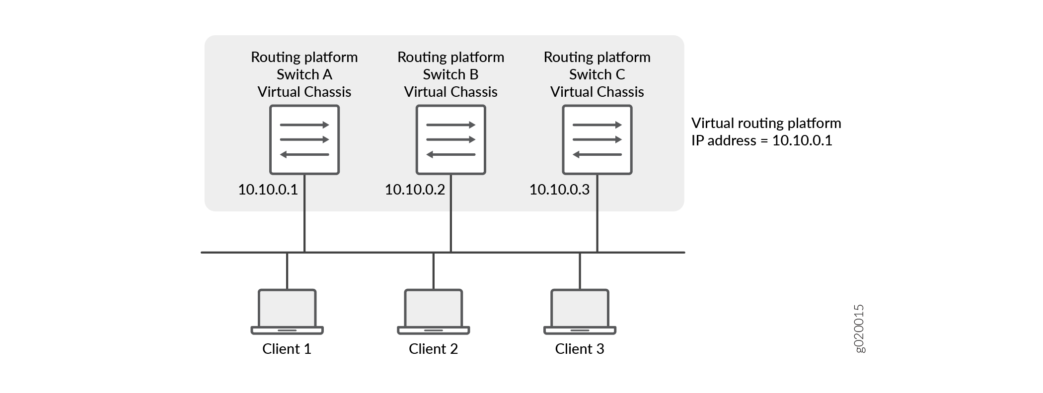
Do not confuse the VRRP primary and backup routing platforms with the primary and backup member switches of a Virtual Chassis configuration. The primary and backup members of a Virtual Chassis configuration compose a single host. In a VRRP topology, one host operates as the primary routing platform and another operates as the backup routing platform, as shown in Figure 3.
VRRP is defined in RFC 3768, Virtual Router Redundancy Protocol. VRRP for IPv6 is defined in draft-ietf-vrrp-ipv6-spec-08.txt, Virtual Router Redundancy Protocol for IPv6. See also draft-ietf-vrrp-unified-mib-06.txt, Definitions of Managed Objects for the VRRP over IPv4 and IPv6.
Even though VRRP, as defined in RFC 3768, does not support authentication, the Junos OS implementation of VRRP supports authentication as defined in RFC 2338. This support is achieved through the backward compatibility options in RFC 3768.
On EX2300 and EX3400 switches, the VRRP protocol must be configured with a Hello interval of 2 seconds or more with dead interval not less than 6 seconds to prevent flaps during CPU intensive operations events such as routing engine switchover, interface flaps, and exhaustive data collection from the packet forwarding engine.
Figure 1 illustrates a basic VRRP topology. In this example, Routers A, B, and C are running VRRP and together make up a virtual router. The IP address of this virtual router is 10.10.0.1 (the same address as the physical interface of Router A).
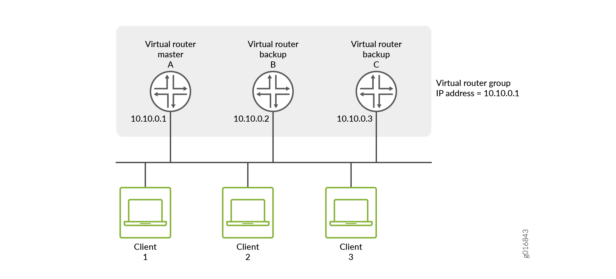
Because the virtual router uses the IP address of the physical interface of Router A, Router A is the primary VRRP router, while routers B and C function as backup VRRP routers. Clients 1 through 3 are configured with the default gateway IP address of 10.10.0.1. As the primary router, Router A forwards packets sent to its IP address. If the primary virtual router fails, the router configured with the higher priority becomes the primary virtual router and provides uninterrupted service for the LAN hosts. When Router A recovers, it becomes the primary virtual router again.
In some cases, during an inherit session, there is a small time frame during which two routers are in Primary-Primary state. In such cases, the VRRP groups that inherit the state do send out VRRP advertisements every 120 seconds. So, it takes the routers up to 120 seconds to recover after moving to Primary-Backup state from Primary-Primary state.
ACX series routers can support up to 64 VRRP group entries. These can be a combination of IPv4 or IPv6 families. If either of the family (IPv4 or IPv6) is solely configured for VRRP, then 64 unique VRRP group identifiers are supported. If both IPv4 and IPv6 families share the same VRRP group, then only 32 unique VRRP identifiers are supported.
ACX Series routers support VRRP version 3 for IPv6 addresses.
ACX5448 router supports RFC 3768 VRRP version 2 and RFC 5798 VRRP version 3. ACX5448 router also supports configuring VRRP over aggregated Ethernet and integrated routing and bridging (IRB) interfaces.
The following limitations apply while configuring VRRP on ACX5448 router:
-
Configure a maximum of 16 VRRP groups.
-
Interworking of VRRP version 2 and VRRP version 3 is not supported.
-
VRRP delegate processing is not supported.
-
VRRP version 2 authentication is not supported.
Figure 1 illustrates a basic VRRP topology
with EX Series switches. In this example, Switches A, B, and C are running VRRP and
together they make up a virtual routing platform. The IP address of this virtual routing
platform is 10.10.0.1 (the same address as the physical interface of
Switch A).
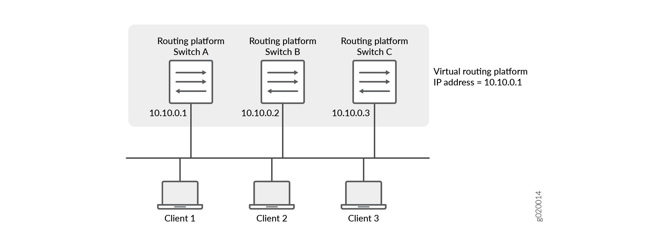
Figure 3 illustrates a basic VRRP
topology using Virtual Chassis configurations. Switch A, Switch B, and Switch C are each
composed of multiple interconnected Juniper Networks EX4200 Ethernet Switches. Each Virtual
Chassis configuration operates as a single switch, which is running VRRP, and together they
make up a virtual routing platform. The IP address of this virtual routing platform is
10.10.0.1 (the same address as the physical interface of Switch A).
Because the virtual routing platform uses the IP address of the physical interface of
Switch A, Switch A is the primary VRRP routing platform, while Switch B and Switch C
function as backup VRRP routing platforms. Clients 1 through 3 are configured with the
default gateway IP address of 10.10.0.1 as the primary router, Switch A,
forwards packets sent to its IP address. If the primary routing platform fails, the switch
configured with the higher priority becomes the primary virtual routing platform and
provides uninterrupted service for the LAN hosts. When Switch A recovers, it becomes the
primary virtual routing platform again.
VRRP and VRRP for IPv6 Overview
You can configure the Virtual Router Redundancy Protocol (VRRP) and VRRP for IPv6 for the following interfaces:
Ethernet
Fast Ethernet
Tri-Rate Ethernet copper
Gigabit Ethernet
10-Gigabit Ethernet LAN/WAN PIC
Ethernet logical interfaces
VRRP and VRRP for IPv6 allow hosts on a LAN to make use of redundant routers on that LAN without requiring more than the static configuration of a single default route on the hosts. The VRRP routers share the IP address corresponding to the default route configured on the hosts. At any time, one of the VRRP routers is the primary (active) and the others are backups. If the primary fails, one of the backup routers becomes the new primary router, thus always providing a virtual default router and allowing traffic on the LAN to be routed without relying on a single router.
VRRP is defined in RFC 3768, Virtual Router Redundancy Protocol.
For VRRP and VRRP for IPv6 overview information, configuration guidelines, and statement summaries, see the Junos OS High Availability User Guide.
Junos OS Support for VRRPv3
The advantage of using VRRPv3 is that VRRPv3 supports both IPv4 and IPv6 address families, whereas VRRPv2 supports only IPv4 addresses.
The following topics describe the Junos OS support for and interoperability of VRRPv3, as well as some differences between VRRPv3 and its precursors:
- Junos OS VRRP Support
- IPv6 VRRP Checksum Behavioral Differences
- VRRP Interoperability
- Upgrading from VRRPv2 to VRRPv3
- Functionality of VRRPv3 Features
Junos OS VRRP Support
In releases earlier than Release 12.2, Junos OS supported RFC 3768, Virtual Router Redundancy Protocol (VRRP) (for IPv4) and Internet draft draft-ietf-vrrp-ipv6-spec-08, Virtual Router Redundancy Protocol for IPv6.
VRRPv3 is not supported on routers that use releases earlier than Junos OS Release 12.2 and is also not supported for IPv6 on QFX10000 switches.
VRRPv3 for IPv6 is supported on QFX10002-60C.
Starting with Release 12.2, Junos OS supports:
RFC 3768, Virtual Router Redundancy Protocol (VRRP)
RFC 5798, Virtual Router Redundancy Protocol (VRRP) Version 3 for IPv4 and IPv6
RFC 6527, Definitions of Managed Objects for Virtual Router Redundancy Protocol Version 3 (VRRPv3)
VRRP (for IPv6) on routers that use Junos OS Release 12.2 and later releases does not interoperate with VRRP (for IPv6) on routers with earlier Junos OS releases because of the differences in VRRP checksum calculations. See IPv6 VRRP Checksum Behavioral Differences.
IPv6 VRRP Checksum Behavioral Differences
You must consider the following checksum differences when enabling IPv6 VRRP networks:
In releases earlier than Junos OS Release 12.2, when VRRP for IPv6 is configured, the VRRP checksum is calculated according to section 5.3.8 of RFC 3768, Virtual Router Redundancy Protocol (VRRP).
Starting with Junos OS Release 12.2, when VRRP for IPv6 is configured, irrespective of VRRPv3 being enabled or not, the VRRP checksum is calculated according to section 5.2.8 of RFC 5798, Virtual Router Redundancy Protocol (VRRP) Version 3 for IPv4 and IPv6.
Moreover, the pseudoheader is included only when calculating the IPv6 VRRP checksum. The pseudoheader is not included when calculating the IPv4 VRRP checksum.
To make the router with Junos OS Release 12.2 (or later Junos OS releases) IPv6 VRRP interoperate with the router running a Junos OS release earlier than Release 12.2, include the
checksum-without-pseudoheaderconfiguration statement at the[edit protocols vrrp]hierarchy level in the router running Junos OS Release 12.2 or later.The
tcpdumputility in Junos OS Release 12.2 and later calculates the VRRP checksum according to RFC 5798, Virtual Router Redundancy Protocol (VRRP) Version 3 for IPv4 and IPv6. Therefore, whentcpdumpparses IPv6 VRRP packets that are received from older Junos OS releases (earlier than Junos OS Release 12.2), thebad vrrp cksummessage is displayed:23:20:32.657328 Out ... -----original packet----- 00:00:5e:00:02:03 > 33:33:00:00:00:12, ethertype IPv6 (0x86dd), length 94: (class 0xc0, hlim 255, next-header: VRRP (112), length: 40) fe80::224:dcff:fe47:57f > ff02::12: VRRPv3-advertisement 40: vrid=3 prio=100 intvl=100(centisec) (bad vrrp cksum b4e2!) addrs(2): fe80::200:5eff:fe00:3,2001:4818:f000:14::1 3333 0000 0012 0000 5e00 0203 86dd 6c00 0000 0028 70ff fe80 0000 0000 0000 0224 dcff fe47 057f ff02 0000 0000 0000 0000 0000 0000 0012 3103 6402 0064 b4e2 fe80 0000 0000 0000 0200 5eff fe00 0003 2001 4818 f000 0014 0000 0000 0000 0001You can ignore this message because it does not indicate VRRP failure.
VRRP Interoperability
In releases earlier than Junos OS Release 12.2, VRRP (IPv6) followed Internet draft draft-ietf-vrrp-ipv6-spec-08, but checksum was calculated based on RFC 3768 section 5.3.8. Starting with Release 12.2, VRRP (IPv6) follows RFC 5798 and checksum is calculated based on RFC 5798 section 5.2.8. Because of the differences in VRRP checksum calculations, IPv6 VRRP configured on routers that use Junos OS Release 12.2 and later releases does not interoperate with IPv6 VRRP configured in releases before Junos OS Release 12.2.
To make the router with Junos OS Release 12.2 (or later Junos
OS releases) IPv6 VRRP interoperate with the router running Junos
OS releases earlier than Release 12.2, include the checksum-without-pseudoheader configuration statement at the [edit protocols vrrp] hierarchy
level in the router with Junos OS Release 12.2 or later.
Here are some general points to know about VRRP interoperability:
If you have configured VRRPv3 (IPv4 or IPv6) on routers that use Junos OS Release 12.2 or later releases, it will not operate with routers that use Junos OS Release 12.1 or earlier releases. This is because only Junos OS Release 12.2 and later releases support VRRPv3.
VRRP (IPv4 or IPv6) configured on routers that use Junos OS Release 12.2 and later releases interoperate with VRRP (IPv4 or IPv6) configured on routers that use releases earlier than Junos OS Release 12.2.
VRRPv3 for IPv4 does not interoperate with the previous versions of VRRP. If VRRPv2 IPv4 advertisement packets are received by a router on which VRRPv3 is enabled, the router transitions itself to the backup state to avoid creating multiple primaries in the network. Due to this behavior, you must be cautious when enabling VRRPv3 on your existing VRRPv2 networks. See Upgrading from VRRPv2 to VRRPv3 for more information.
Note:VRRPv3 advertisement packets are ignored by the routers on which previous versions of VRRP are configured.
Upgrading from VRRPv2 to VRRPv3
Enable VRRPv3 in your network only if VRRPv3 can be enabled on all the VRRP routers in your network.
Enable VRRPv3 on your VRRPv2 network only when upgrading from VRRPv2 to VRRPv3. Mixing the two versions of VRRP is not a permanent solution.
VRRP version change is considered catastrophic and disruptive and may not be hitless. The packet loss duration depends on many factors, such as number of VRRP groups, the interfaces and FPCs involved, and the load of other services and protocols running on the router.
Upgrading from VRRPv2 to VRRPv3 must be done very carefully to avoid traffic loss, due to these considerations:
It is not possible to configure VRRPv3 on all routers simultaneously.
During the transition period, both VRRPv2 and VRRPv3 operate in the network.
Changing VRRP versions restarts the state machine for all VRRP groups.
VRRPv3 (for IPv4) routers default to the backup state when they get VRRPv2 (for IPv4) advertisement packets.
VRRPv2 (for IPv4) packets are always given the highest priority.
Checksum differences between VRRPv2 and VRRPv3 (for IPv6) can create multiple primary routers.
Disable VRRPv3 (for IPv6) on the backup routers while upgrading to avoid creating multiple primary routers.
Table 1 illustrates the steps and events that take place during a VRRPv2 to VRRPv3 transition. In Table 1, two VRRPv2 routers, R1 and R2, are configured in two groups, G1 and G2. Router R1 acts as the primary for G1, and Router R2 acts as the primary for G2.
|
|
For IPv4 |
For IPv6 |
|
|
When enabling VRRPv3, make sure that VRRPv3 is enabled on all the VRRP routers in the network because VRRPv3 (IPv4) does not interoperate with the previous versions of VRRP. For example, if VRRPv2 IPv4 advertisement packets are received by a router on which VRRPv3 is enabled, the router transitions itself to the backup state to avoid creating multiple primaries in the network.
You can enable VRRPv3 by configuring the version-3 statement at the [edit protocols vrrp] hierarchy level
(for IPv4 or IPv6 networks). Configure the same protocol version on
all VRRP routers on the LAN.
Functionality of VRRPv3 Features
Some Junos OS features differ in VRRPv3 from previous VRRP versions.
VRRPv3 Authentication
When VRRPv3 (for IPv4) is enabled, it does not allow authentication.
The
authentication-typeandauthentication-keystatements cannot be configured for any VRRP groups.You must use non-VRRP authentication.
VRRPv3 Advertisement Intervals
VRRPv3 (for IPv4 and IPv6) advertisement intervals must be set
with the fast-interval statement at the [edit interfaces interface-name unit 0 family inet address ip-address vrrp-group group-name] hierarchy level.
Do not use the
advertise-intervalstatement (for IPv4).Do not use the
inet6-advertise-intervalstatement (for IPv6).
Unified ISSU for VRRPv3
Design changes for VRRP unified in-service software upgrade (ISSU) are made in Junos OS Release 15.1 to achieve the following functionality:
Maintain protocol adjacency with peer routers during unified ISSU. Protocol adjacency created on peer routers for the router undergoing unified ISSU should not flap, which means that VRRP on the remote peer router should not flap.
Maintain interoperability with competitive or complementary equipment.
Maintain interoperability with other Junos OS releases and other Juniper Network products.
The values of the following configurations (found at the [edit interfaces interface-name unit 0 family
inet address ip-address vrrp-group group-name] hierarchy level) need to be kept at
maximum values to support unified ISSU:
On the primary router, the advertisement interval (the
fast-intervalstatement) needs to be kept at 40950 milliseconds.On the backup router, the primary-down interval (the
advertisements-thresholdstatement) needs to be kept at the largest threshold value.
This VRRP unified ISSU design only works for VRRPv3. It is not supported on VRRPv1 or VRRPv2. Other limitations include the following:
The VRRP unified ISSU takes care of VRRP only. Packet forwarding is the responsibility of the Packet Forwarding Engine. The Packet Forwarding Engine unified ISSU should ensure uninterrupted traffic flow.
VRRP is not affected by any change event during unified ISSU, for example, the switchover of the primary Routing Engine to backup or the backup Routing Engine to primary.
VRRP might stop and discard any running timer before entering into unified ISSU. This means the expected action upon the expiry of the timer never takes place. However, you can defer unified ISSU until the expiration of all running timers.
Unified ISSU at both local and remote routers cannot be done simultaneously.
VRRP failover-delay Overview
Failover is a backup operational mode in which the functions of a network device are assumed by a secondary device when the primary device becomes unavailable because of a failure or a scheduled down time. Failover is typically an integral part of mission-critical systems that must be constantly available on the network.
VRRP does not support session synchronization between members. If the primary device fails, the backup device with the highest priority takes over as primary and will begin forwarding packets. Any existing sessions will be dropped on the backup device as out-of-state.
A fast failover requires a short delay. Thus, failover-delay configures the failover delay time, in milliseconds, for VRRP and VRRP for IPv6 operations. Junos OS supports a range of 50 through 100000 milliseconds for delay in failover time.
The VRRP process (vrrpd) running on the Routing Engine communicates a VRRP primary role change to the Packet Forwarding Engine for every VRRP session. Each VRRP group can trigger such communication to update the Packet Forwarding Engine with its own state or the state inherited form an active VRRP group. To avoid overloading the Packet Forwarding Engine with such messages, you can configure a failover-delay to specify the delay between subsequent Routing Engine to Packet Forwarding Engine communications.
The Routing Engine communicates a VRRP primary role change to the Packet Forwarding Engine to facilitate necessary state change on the Packet Forwarding Engine, such as reprogramming of Packet Forwarding Engine hardware filters, VRRP sessions and so on. The following sections elaborate the Routing Engine to Packet Forwarding Engine communication in two scenarios:
When failover-delay Is Not Configured
Without failover-delay configured, the sequence of events for VRRP sessions operated from the Routing Engine is as follows:
When the first VRRP group detected by the Routing Engine changes state, and the new state is primary, the Routing Engine generates appropriate VRRP announcement messages. The Packet Forwarding Engine is informed about the state change, so that hardware filters for that group are reprogrammed without delay. The new primary then sends gratuitous ARP message to the VRRP groups.
The delay in failover timer starts. By default, failover-delay timer is:
500 miliseconds—when the configured VRRP announcement interval is less than 1 second.
2 seconds—when the configured VRRP announcement interval is 1 second or more, and the total number of VRRP groups on the router is 255.
10 seconds—when the configured VRRP announcement interval is 1 second or more, and the number of VRRP groups on the router is more than 255.
The Routing Engine performs one-by-one state change for subsequent VRRP groups. Every time there is a state change, and the new state for a particular VRRP group is primary, the Routing Engine generates appropriate VRRP announcement messages. However, communication toward the Packet Forwarding Engine is suppressed until the failover-delay timer expires.
After failover-delay timer expires, the Routing Engine sends message to the Packet Forwarding Engine about all VRRP groups that managed to change the state. As a consequence, hardware filters for those groups are reprogrammed, and for those groups whose new state is primary, gratuitous ARP messages are sent.
This process repeats until state transition for all VRRP groups is complete.
Thus, without configuring failover-delay, the full state transition (including states on the Routing Engine and the Packet Forwarding Engine) for the first VRRP group is performed immediately, while state transition on the Packet Forwarding Engine for remaining VRRP groups is delayed by at least 0.5-10 seconds, depending on the configured VRRP announcement timers and the number of VRRP groups. During this intermediate state, receiving traffic for VRRP groups for state changes that were not yet completed on the Packet Forwarding Engine might be dropped at the Packet Forwarding Engine level due to deferred reconfiguration of hardware filters.
When failover-delay Is Configured
When failover-delay is configured, the sequence of events for VRRP sessions operated from the Routing Engine is modified as follows:
The Routing Engine detects that some VRRP groups require a state change.
The failover-delay starts for the period configured. The allowed failover-delay timer range is 50 through 100000 miliseconds.
The Routing Engine performs one-by-one state change for the VRRP groups. Every time there is a state change, and the new state for a particular VRRP group is primary, the Routing Engine generates appropriate VRRP announcement messages. However, communication toward the Packet Forwarding Engine is suppressed until the failover-delay timer expires.
After failover-delay timer expires, the Routing Engine sends message to the Packet Forwarding Engine about all VRRP groups that managed to change the state. As a consequence, hardware filters for those groups are reprogrammed, and for those groups whose new state is primary, gratuitous ARP messages are sent.
This process repeats until state transition for all VRRP groups is complete.
Thus, when failover-delay is configured even the Packet Forwarding Engine state for the first VRRP group is deferred. However, the network operator has the advantage of configuring a failover-delay value that best suits the need of the network deployment to ensure minimal outage during VRRP state change.
failover-delay influences only VRRP sessions operated by the VRRP process (vrrpd) running on the Routing Engine. For VRRP sessions distributed to the Packet Forwarding Engine, failover-delay configuration has no effect.
Change History Table
Feature support is determined by the platform and release you are using. Use Feature Explorer to determine if a feature is supported on your platform.