SCTP Overview
Stream Control Transmission Protocol (SCTP) is a transport-layer protocol that ensures reliable, in-sequence transport of data. SCTP provides multihoming support where one or both endpoints of a connection can consist of more than one IP address. This enables transparent failover between redundant network paths.
Understanding Stream Control Transmission Protocol
Stream Control Transmission Protocol (SCTP) is a robust transport layer protocol within the Internet protocol suite, operating alongside UDP and TCP. It is designed to offer reliable, connection-oriented transport for various Internet applications. Key features of SCTP include:
-
Multi-stream Protocol: SCTP supports multiple streams of messages for each endpoint, catering to applications that require different message priorities and strict ordering within streams.
-
User Data Fragmentation: To handle messages exceeding the path's maximum transmission unit (MTU), SCTP fragments the data into chunks, marking the last chunk with a specific flag. The receiver side reassembles these chunks before passing the complete message to the upper-layer protocol.
-
Chunk Bundling:
SCTP allows bundling chunks from multiple messages into a single SCTP packet, facilitating efficient data transfer. The receiver disassembles these chunks before delivering them to the upper-layer protocol. -
Packet Validation:
SCTP includes a verification tag in its header to uniquely identify association sessions. This tag helps protect against masquerade attacks and prevents the processing of stale SCTP packets from previous associations. -
Multihoming Support:
SCTP allows endpoints to specify a list of local transport addresses during association setup, promoting high availability for data transfer by establishing routes for each destination address.
Moreover, SCTP offers transparent failover between redundant network paths, making it an ideal choice for applications requiring reliable, in-sequence data transport. It operates on top of connectionless packet networks like IP and supports single or multi-IP scenarios.
Additionally, SCTP finds application in transporting signaling messages for 3G mobile networks through protocols such as M3UA, M2UA, or SUA. It is optimized to avoid multithread infrastructure problems during high traffic, enhance association searching rate, and improve Finite State Machine (FSM) for retransmission cases.
SCTP is particularly well-suited for applications requiring monitoring and loss-of-session detection. Its heartbeat mechanism monitors session connectivity, ensuring a reliable and secure transport with minimal end-to-end delay and quick failover time in the event of network failures.
- SCTP Services
- SCTP Limitations and Constraints
- SCTP Features Overview
- Understanding Central Point Architecture Support for SCTP
- SCTP Support for Virtual Routing and Forwarding (VRF)
- SCTP One to Many Style Socket
SCTP Services
SCTP provides the following services:
-
Aggregate Server Access Protocol (ASAP)
-
Bearer-independent Call Control (BICC)
-
Direct Data Placement Segment chunk (DDP-segment)
-
Direct Data Placement Stream session control (DDP-stream)
-
Diameter in a DTLS/SCTP DATA chunk (Diameter-DTLS)
-
Diameter in a SCTP DATA chunk (Diameter-SCTP)
-
DPNSS/DASS 2 extensions to IUA Protocol (DUA)
-
Endpoint Handlescape Redundancy Protocol (ENRP)
-
H.248 Protocol (H248)
-
H.323 Protocol (H323)
-
ISDN User Adaptation Layer (IUA)
-
MTP2 User Peer-to-Peer Adaptation Layer (M2PA)
-
MTP2 User Adaptation Layer (M2UA)
-
MTP3 User Adaptation Layer (M3UA)
-
Other unspecified-configured SCTP payload protocols (Others)
-
Q.IPC
-
Reserved
-
S1 Application Protocol (S1AP)
-
Simple Middlebox Configuration (SIMCO)
-
SCCP User Adaptation Layer (SUA)
-
Transport Adapter Layer Interface (TALI)
-
V5.2 User Adaptation Layer (V5UA)
-
X2 Application Protocol (X2AP)
SCTP Limitations and Constraints
SCTP has the following limitations and constraints:
-
IP Addresses
-
Only static IP NAT is supported; the interface packets (from one side: client or server) coming in must belong to the same zone.
-
-
Policies
-
Dynamic policy is not supported. You must configure all policies for SCTP sessions.
-
When policies are deleted, the related sessions and associations are cleared.
-
You configure one policy to permit SCTP traffic from all client IPs to all server IPs, and another policy to permit SCTP traffic from server IPs to client IPs. If one policy has an SCTP profile, then the same SCTP profile is needed for the reverse policy.
-
If you configure different policies for each session belonging to one association, there will be multiple policies related to one association, and the SCTP packet management (drop, rate-limit, and so on) uses the profile attached to the handling SCTP session's policy.
-
The applications used in the security policies to permit the SCTP ALG traffic cannot be configured using the
application-protocol
                                    ignore
option. This condition is applicable even if the SCTP ALG inspection is not configured.
-
-
SCTP enable/disable is controlled by whether there is a SCTP profile configured.
-
If no profile is attached to a policy, SCTP packets are forwarded without inspection.
-
If a profile with the
nat-onlyoption is attached to a policy, then only NAT translation is done on the SCTP packets matching the policy. If a profile does not have thenat-onlyoption set, then both NAT translation and SCTP inspection are done on each SCTP packet matching the policy. -
If you disable SCTP, all associations are deleted, and subsequent SCTP packets are passed or dropped according to the policy.
-
If you enable SCTP, all existing SCTP sessions must be cleared or the traffic matching old sessions will be forwarded without any inspection from the SCTP module.
If you want to enable SCTP again, all the running SCTP communications will be dropped, because no associations exist. New SCTP communications can establish an association and perform the inspections.
Note:Clear old SCTP sessions when SCTP is reenabled; doing this will avoid any impact caused by the old SCTP sessions on the new SCTP communications.
-
If you add an SCTP profile to an existing policy, you must do one of the following: clear related sessions or remove the old policy and create a new policy.
-
If you change the timeout value in the SCTP profile, the configured handshake and the timeout value in existing associations will not change.
-
-
SCTP Rate Limiting
-
Any change in the rate-limiting configuration will not affect the subsequent traffic of existing associations. It will apply to the newly established associations.
-
The supported protocol decimal value is from 0 to 63. This value includes 48 IANA assigned protocols and 16 unassigned protocols.
-
A maximum of 80 addresses are rate limited in one profile.
-
A maximum of 10 protocols are rate limited for one address in one profile.
-
The supported rate limit value is from 1 to 12000.
-
-
SCTP Payload Protocol Blocking
-
Any change in the protocol-blocking configuration immediately impacts the subsequent traffic of existing associations.
-
The supported protocol decimal value is from 0 to 63. This value includes 48 IANA assigned protocols and 16 unassigned protocols.
-
-
An SCTP endpoint also supports NAT-PT in two directions, from an IPv4 address format to an IPv6 address format, and vice versa. SCTP module does not support IPv4 or IPv6 mixed-up multihoming and IPv4 or IPv6 mixed-up NAT-PT.
-
For static NAT to work, the interfaces packets (from one side: client or server side) coming in must belong to the same zone.
-
For multihome cases, only IPv4 address parameter in INIT or INIT_ACK is supported.
-
Only static NAT is supported for SCTP.
-
Only established SCTP associations are synchronized to peer sessions.
-
SCTP sessions are not deleted with associations; they time out in 30 minutes, which is the default value. The timeout value is configurable and can be changed.
-
If the 4-way handshake process is not handled on one node, and is handled instead on two nodes (for example, two sessions on two nodes in active/active mode) or if the cluster is in failover before the 4-way handshake is completed, the association will not be established successfully.
-
Unified in-service software upgrade (ISSU) to earlier Junos OS releases is not supported.
-
The M3UA/SCCP message parsing is checked , but the M3UA/SCCP stateful inspection is not checked.
-
Only ITU-T Rec. Q.711-Q.714 (07/96) standard is supported. ANSI, ETSI, China, and other standards are not supported.
-
Only RFC 4960 is supported.
-
VPN session affinity does not support GPRS tunneling protocol (GTP) and Stream Control Transmission Protocol (SCTP).
SCTP Features Overview
The following are the important features of SCTP:
-
Multihoming support where one or both endpoints of a connection can consist of more than one IP address. This enables transparent failover between redundant network paths.
-
Delivery of data in chunks within an independent stream eliminates unnecessary head-of-line blocking.
-
Path selection and monitoring functionality to select a primary data transmission path and test the connectivity of the transmission path.
-
Validation and acknowledgment mechanisms protect against flooding attacks and provide notification of duplicated or missing data chunks.
-
Improved error detection suitable for jumbo Ethernet frames.
Understanding Central Point Architecture Support for SCTP
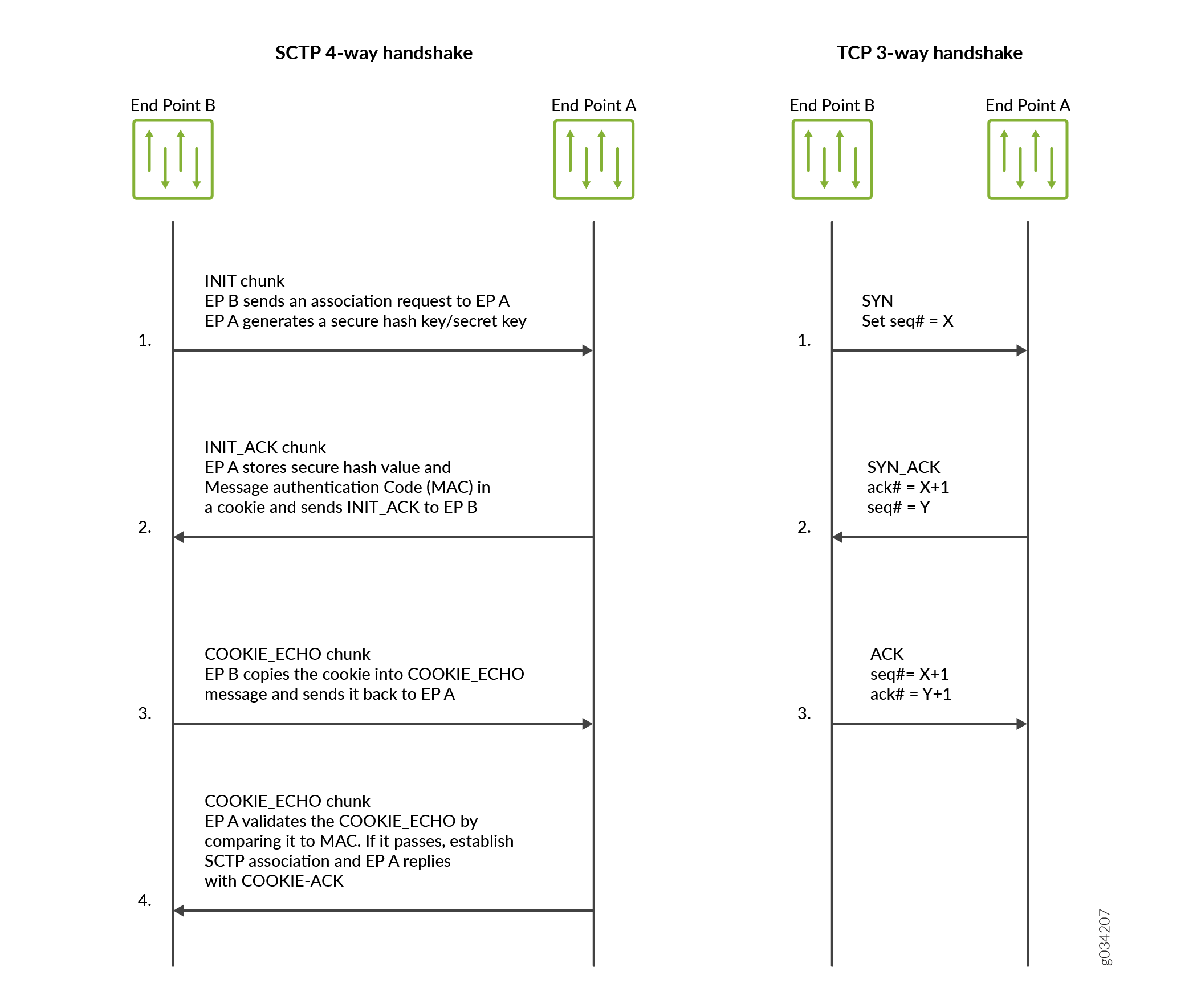
A Stream Control Transmission Protocol (SCTP) association is a connection between two SCTP endpoints. Each SCTP endpoint identifies the association with a tag. During an SCTP association setup, two SCTP endpoints exchange their own tags for receiving packets. During the exchange of packets between two SCTP endpoints, both the source address and the destination address can change in the association life cycle.
A separate SCTP session will be created for each of the first three packets—that is, one session for INIT, INIT-ACK, and COOKIE-ECHO, respectively. Because, the reverse-direction traffic has its own session, the session can no longer match the existing forward-direction session and pass through automatically. Therefore, similar to the forward-direction policy, an explicit policy is needed for approving the reverse-direction SCTP traffic. In this scenario, the SCTP flow session requires a bidirectional policy configuration to be established for even a basic connection.
Use Feature Explorer to confirm platform and release support for specific features.
Review the Platform-Specific SCTP ALG Behavior section for notes related to your platform.
SCTP Support for Virtual Routing and Forwarding (VRF)
The VRF (Virtual Routing and Forwarding) feature allows for the management of remote IP addresses. SCTP client, before initiating new SCTP association, it should set socket option for route table index/VRF index, if egress interface to SCTP server configured inside VRF, other wise association will not get established as SCTP client will use default/global routing instance for association establishment. On SCTP server side, if VRF index socket option is not set on listening socket, association request received on all VRFs will be entertained but if VRF index socket option is set on listening socket, association establishment request coming on that particular VRF will only be entertained.
Application can either set socket option with custom flag to provide route table index to SCTP to handle VRF-based SCTP association, to place association in that particular association, or let SCTP kernel to choose VRF for association during establishment in process of 4-way handshake, based on VRF in which ingress interface is configured.
When a SCTP association is established over a VRF instance, the kernel must take into account an additional parameter, the unique VRF ID, when looking up unique associations by using the existing 4-tuple used in SCTP (source IP, source port, destination IP, destination port).
-
Inbound SCTP packets over VRF:
When a SCTP packet arrives on an ingress interface, a lookup is conducted using the 5-tuple (source IP, source port, destination IP, destination port, and 'VRF ID on which the packet was received') to determine if there is an existing SCTP association present in the kernel.
-
Outbound SCTP packets over VRF:
For every SCTP packet that is sent out from the kernel, the corresponding VRF ID is obtained from the association data using the 5-tuple (source IP, source port, destination IP, destination port, and 'VRF ID on which the packet is to be sent').
SCTP One to Many Style Socket
SCTP supports two socket styles: 1 to 1 (comparable to TCP) and 1 to Many (allowing multiple active associations on a single socket). The latter facilitates communication with several peer endpoints simultaneously, using association identifiers (assoc-id) to distinguish between them.
The below system APIs are used by the application avail the SCTP 1:1 or 1:N style socket:
System Calls for 1 to 1 Style Socket
-
Server role: socket(), bind(), listen(), accept(), write()/read(), close()
-
Client role: socket(), connect(), write()/read(), close()
System Calls for 1 to Many Style Socket
-
Server role: socket(), bind(), listen(), recvmsg(), sendmsg(), close()
-
Client role: socket(), sendmsg(), recvmsg(), close()
See Also
SCTP Packet Structure Overview
An SCTP packet consists of the following sections:
Figure 2 illustrates the structure of the SCTP packet.
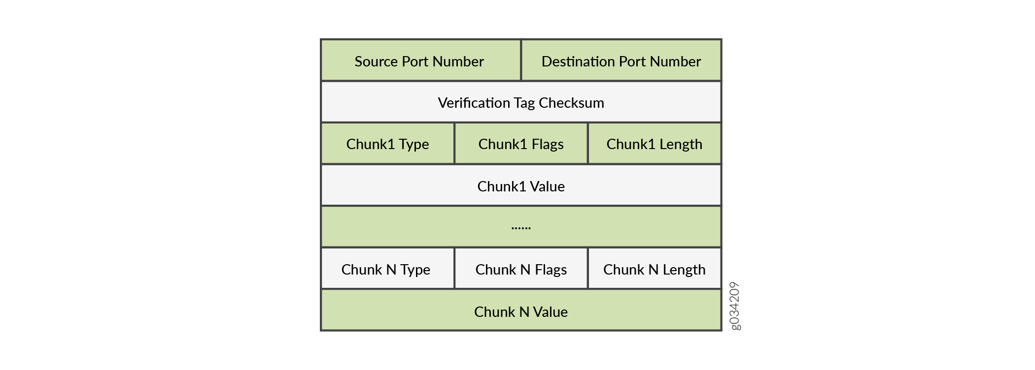
Common Header Section
All SCTP packets require a common header section. This section occupies the first 12 bytes of the packet. Table 1 describes the fields in the common header section:
|
Field |
Description |
|---|---|
|
Source port number |
Identifies the sending port. |
|
Destination port number |
Identifies the receiving port. The hosts use the destination port number to route the packet to the appropriate destination or an application. |
|
Verification tag |
Distinguishes stale packets from a previous connection. This is a 32-bit random value created during initialization. |
|
Checksum |
Uses the cyclic redundancy check (CRC32) algorithm to detect errors that might have been introduced during data transmission. |
Data Chunk Section
Data chunk section—This section occupies the remaining portion of the packet. Table 2 describes the fields in the data chunk section:
|
Field |
Description |
|---|---|
|
Chunk Type |
Identifies the contents of the chunk value field. This is 1- byte long. |
|
Chunk Flags |
Consists of 8 flag-bits whose definition varies with the chunk type. The default value is zero. This indicates that no application identifier is specified by the upper layer for the data. |
|
Chunk Length |
Specifies the total length of the chunk in bytes. This field is 2 - bytes long. If the chunk does not form a multiple of 4 bytes (that is, the length is not a multiple of 4) it is implicitly padded with zeros which are not included in the chunk length. |
|
Chunk Value |
A general purpose data field. |
The resource manager (RM) allows 8 source IP addresses and 8 destination IP addresses during an SCTP communication.
Understanding SCTP Multihoming
A Stream Control Transmission Protocol (SCTP) endpoint can be a multihomed host with either all IPv4 addresses or all IPv6 addresses. In Figure 3, endpoint A is connected to two IPv4 addresses, and endpoint B is connected to two IPv4 addresses. Therefore, endpoint A and endpoint B can set up an association using four different pairs of IP addresses, resulting in four valid paths for communication.

In Figure 4, endpoint A is connected to two IPv6 addresses, and endpoint B is connected to two IPv6 addresses. Therefore, endpoint A and endpoint B can set up an association using four different pairs of IP addresses, resulting in four valid paths for communication.

Understanding SCTP Multichunk Inspection
The Stream Control Transmission Protocol (SCTP) firewall
checks all chunks in a message and then permits or drops the packet
based on the policy. Use the set security gprs sctp multichunk-inspection
enable command to enable SCTP multichunk inspection to check
all chunks in a message. Use the delete security gprs sctp multichunk-inspection
enable or set security gprs sctp multichunk-inspection
disable command to disable SCTP multichunk inspection to check
only the first chunk.
After enabling SCTP multichunk inspection, the SCTP firewall checks all chunks in a message and permits or drops the packet. The SCTP firewall drops the packet in the following cases:
The layout of the SCTP chunks do not follow RFC 4960.
A control chunk cannot pass the inspection of the SCTP finite state machine (FSM) or sanity checks.
A data chunk is not allowed to pass the SCTP profile because of the SCTP FSM or sanity checks.
A data chunk is not allowed to pass through the SCTP profile because of protocol blocking or rate limiting. The SCTP firewall resets this chunk to a null protocol data unit (PDU) and continues to check the next chunk. A data chunk is set to a null PDU based on the following rules:
When you set the null PDU value to
0xFFFFusing theset security gprs sctp nullpdu protocol ID-0xFFFFcommand, then the payload protocol identifier value is replaced with0xFFFFand the user data field is not modified.When you set the null PDU value to
0x0000using theset security gprs sctp nullpdu protocol ID-0x0000command, then the payload protocol identifier value is replaced with0x0000and the first four bytes of the user data field is replaced with zeroes.
If all chunks in a packet are null PDUs, the SCTP firewall drops the packet.
Understanding SCTP Behavior in Chassis Cluster
In a chassis cluster configuration mode, the SCTP configuration and the established SCTP association is synced with the peer device. The SCTP module supports both active-active and active-passive modes.
The established SCTP association sends a creation or deletion message to the peer whenever an association is created or deleted on the active device. The secondary device adds or deletes an association respectively upon receiving the message from the established SCTP association. SCTP module then registers the corresponding callback function to receive and handle this message. There is no continuous timer sync between the two associations.
SCTP module will register a cold start sync function when a secondary device joins the cluster or reboots. The SCTP cold start function is called to sync all SCTP associations with the peer devices at the same time.
After the switchover, the established SCTP associations will remain functioning, but the associations in the progress of establishment will be lost and the establishment procedure needs to be re-initiated. It is also possible that the associations in the progress of teardown miss the ack message and leaves unestablished SCTP associations in the firewall. These associations will be cleaned up when the timer expires (5 hours by default) due to no activity in the association.
You should configure all policies for your required SCTP sessions. For example, suppose you have endpoints A and B. Endpoint A has one SCTP association with x number of IPs (IP_a1, IP_a2, IP_a3...IP_ax). Endpoint B has one SCTP association with y number of IPs (IP_b1, IP_b2, IP_b3...IP_by.) The policy on the security device should permit all possible x*y paths in both directions.
When an SCTP association is removed, the related SCTP sessions still exist and time out by themselves.
Platform-Specific SCTP ALG Behavior
Use Feature Explorer to confirm platform and release support for specific features.
Use the following table to review platform-specific storage media behaviors for your platform:
|
Platform |
Difference |
|---|---|
|
SRX Series |
|