Monitoring GTP Traffic
The GPRS Tunneling Protocol (GTP) establishes a GTP tunnel for a user equipment, between a Service gateway GPRS support node (SGSN) and gateway GPRS support node (GGSN), and an SGSN and mobility management entity (MME). The SGSN receives packets from the user equipment and encapsulates them within a GTP header before forwarding them to the GGSN through the GTP tunnel. When the GGSN receives the packets, it decapsulates the packets and forwards the packets to the external host.
Understanding GTP-U Inspection
The GPRS tunneling protocol user plane (GTP-U) inspection performs security checks on GTP-U packets. When GTP-U inspection is enabled, the invalid GTP-U packets are blocked and the GPRS support node (GSN) is protected from a GTP-U attack.
Once GTP-U inspection is enabled and depending on the device configuration, GTP-U inspection might include checks on GTP-in-GTP packets, end-user authorization, packet sequence validity, and tunnel validity. If any configured check fails, the GTP-U packet is dropped.
If the GTP-U inspection is enabled while the GTP-U distribution
is disabled then the following message is displayed: GTP-U inspection is enabled, please enable GTP-U distribution to
ensure that GTP-U packets are inspected by the proper inspectors,
and avoid dropping GTP-U packets wrongly. Execute CLI “set security
forwarding-process application-services enable-gtpu-distribution"
to enable GTP-U distribution. It is strongly recommended
that when you enable GTP-U inspection, GTP-U distribution should also
be enabled.
Use Feature Explorer to confirm platform and release support for specific features.
Review the Platform-Specific GTP-U Inspection Behavior section for notes related to your platform.
The following list describes the various types of GTP-U inspections that are performed on the traffic:
GTP-U tunnel check—The GTP-U module checks that the GTP-U packet matches a GTP tunnel. If no tunnel matches the GTP-U packet, then the GTP-U packet is dropped.
GTP-in-GTP check—In the SPU, the GTP module checks to ensure that the GTP-U payload is not a GTP packet. If the payload is a GTP packet, then the GTP packet is dropped.
End-user address check—If the user tunnel is found for the GTP-U packet, then the GTP-U module checks for the end-user address. If the GTP-U payload address does not match the end-user address, then the GTP-U packet is dropped.
Starting in Junos OS Release 15.1X49-D40 and Junos OS Release 17.3R1, the end-user address in certain scenarios is not carried in GTP create messages. For example, if DHCPv4 is used for IPv4 address allocation, the IPv4 address field in the GTP create message will be set to
0.0.0.0. The user equipment and GGSN/PGW get the address from the DHCP server. In this scenario, the GTP module cannot get the address for the end-user address check. Subsequently, if this configuration is enabled, the GTP create message will be dropped.Sequence number check—The GTP-U module compares the GTP-U packet sequence number with the sequence number stored in the GTP-U tunnel. If it is not in the specified range, then the GTP-U packet is dropped. If it is in the range, then the GTP-U tunnel refreshes the sequence number and allows the GTP-U packet to pass.
At the end of the GTP-U inspection, the GTP-U tunnel refreshes the timers and counters.
Understanding GTP Tunnel Enhancements
A GPRS tunneling protocol (GTP) tunnel is a channel between two GPRS support nodes through which two hosts exchange data. The GTP tunnel consists of the GTP control plane (GTP-C) and GTP user plane (GTP-U). GTP-C is used to signaling between the gateway GPRS support node (GGSN) and the serving GPRS support node (SGSN), while the GTP-U tunnel is used to encapsulate and route the user plane traffic across multiple signaling interfaces.
GTP handling is enhanced to update the GTP tunnel and session lifetime to avoid GTP tunnel timeout issues. The GTP tunnel timeout value is configured in the GTP profile and bound to the GTP user plane (GTP-U) tunnel. The timer value is refreshed when the data traffic reaches the GTP-U tunnel and the timer value decreases when the GTP-U tunnel is in idle state. The GTP-U tunnel is deleted when the timer value decreases to zero and the corresponding GTP-C tunnel is also deleted when all GTP-U tunnels bound to the GTP-C tunnels are deleted.
When GTP-U inspection is disabled, data traffic is unable to refresh the GTP-U tunnel after the timer value expires and all GTP tunnels timeout even though data traffic flows across the tunnels. In this scenario, since the GTP tunnels need to be updated, the device drops the update request as the GTP-U tunnel is not present.
To avoid GTP tunnel timeout issues, even if the GTP user validation
is disabled, the GTP-U traffic can refresh the GTP tunnel. GTP-U traffic
can refresh only GTPv1 and GTPv2 tunnels, and not GTPv0 tunnels. You
need to configure the set security forwarding-process application-services
enable-gtpu-distribution command to avoid aging of or expiry
of the GTP tunnels.
The GTP-U tunnel has a session attach flag that is checked when scanning the GTP-U tunnels. If the session attach flag is present in the tunnel, the timer value does not decrease and prevents the tunnel from being deleted while the tunnel is in service.
Understand Validation of IP Address in GTP Messages
IP addresses in GPRS tunneling protocol (GTP) message on Gp or the S8 interface are validated with the configured IP group list to prevent attacks. IP group list is a list of IP addresses that belongs to all kinds of network equipment. You must configure the IP addresses that belongs to network equipment in the IP group list.
S8 - This interface connects an SGW in a visited PLMN (VPLM) and a PGW in a home PLMN (HPLMN). S8 is the inter-PLMN variant of S5. The S8 interface is equivalent to the Gp interface in a 3G mobile network.
The GTP firewall determines if the IP addresses in GTP messages and matches with the configured IP group list, and following action takes place-
-
If the IP addresses are found in the IP group list, the GTP messages are considered valid and forwarded to Packet and Forwarding Engine.
-
If the IP addresses are not found in the IP group list, the GTP messages are dropped.
IP Group Setup in GTP Message
IP group is a list of IP addresses that belongs to all kinds of network equipment. IP group name(s) are referenced in GTP profiles. The GTP firewall applies configured policies in incoming and outgoing IP addresses in GPRS tunneling protocol (GTP) message mentioned in Table 2 and Table 3.
For example, the traffic between client and server in Figure 1, there are two policies configured.
-
GTP Policy Out is for the traffic from client to server.
-
GTP Policy In is for the traffic from server to client.
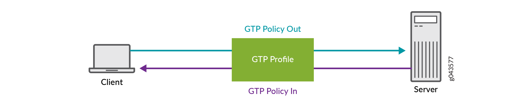
All the IP addresses of client and server must be configured in the IP group list and bound to the GTP Policy Out and GTP Policy In policies.
There are two different types of groups are introduced for different IP addresses. One is for NE IP addresses group, and the other is for User Equipment (UE) IP addresses group listed as in Table 1.
|
Network Types |
Network Equipment IP Address |
User Equipment IP Address |
|---|---|---|
|
2G(GPRS) and 3G(UMTS) |
RNC, SGSN and GGSN |
End User Address |
|
4G(LTE) |
eNodeB, MME, SGW and PGW |
PDN Address Allocation (PAA) |
When GTP messages comes to message handler stage, network equipment IP addresses group and user equipment IP addresses group are validated respectively based on the parsed information elements and IP address header information.
-
Network equipment IP addresses group: IP address header and information element IP address in GTP message are compared against the configured network equipment IP addresses group list (if exist). If the NE IP address is found in the configured NE IP addresses group, pass the data packet to UE IP addresses group else drop the packet.
-
User equipment IP addresses group: All end user IP addresses are validated against the configured user equipment IP addresses group list. If the user equipment IP address is found in the configured user equipment IP addresses group, pass the data packet else drop the packet.
Supported GTP messages
There are many types of messages pass through Gp or S8 interfaces, some of the supported GTP messages are following.
|
Message Type |
GTP Message |
Reference in TS 29.060 |
|---|---|---|
|
1 |
Echo Request |
7.4.1 |
|
2 |
Echo Response |
7.4.2 |
|
16 |
Create PDP Context Request |
7.5.1 |
|
17 |
Create PDP Context Response |
7.5.2 |
|
18 |
Update PDP Context Request |
7.5.3 |
|
19 |
Update PDP Context Response |
7.5.4 |
|
20 |
Delete PDP Context Request |
7.5.5 |
|
21 |
Delete PDP Context Response |
7.5.6 |
|
22 |
Create AA PDP Context Request |
7.5.7 |
|
23 |
Create AA PDP Context Response |
7.5.8 |
|
24 |
Delete AA PDP Context Request |
7.5.9 |
|
25 |
Delete AA PDP Context Response |
7.5.10 |
|
Message Type |
GTP Message |
Reference in TS 29.060 |
|---|---|---|
|
1 |
Echo Request |
7.2.1 |
|
2 |
Echo Response |
7.2.2 |
|
16 |
Create PDP Context Request |
7.3.1 |
|
17 |
Create PDP Context Response |
7.3.2 |
|
18 |
Update PDP Context Request |
7.3.3 |
|
19 |
Update PDP Context Response |
7.3.4 |
|
20 |
Delete PDP Context Request |
7.3.5 |
|
21 |
Delete PDP Context Response |
7.3.6 |
|
Message Type |
GTP Message |
Reference 3GPP TS 29.274 |
|---|---|---|
|
1 |
Echo Request |
23.007 |
|
2 |
Echo Response |
23.007 |
|
32 |
Create Session Request |
29.274 |
|
33 |
Create Session Response |
29.274 |
|
36 |
Delete Session Request |
29.274 |
|
37 |
Delete Session Response |
29.274 |
|
34 |
Modify Bearer Request |
29.274 |
|
35 |
Modify Bearer Response |
29.274 |
|
95 |
Create Bearer Request |
29.274 |
|
96 |
Create Bearer Response |
29.274 |
|
97 |
Update Bearer Request |
29.274 |
|
98 |
Update Bearer Response |
29.274 |
|
99 |
Delete Bearer Request |
29.274 |
|
100 |
Delete Bearer Response |
29.274 |
IEs involved in IP validity
The following are the information elements (IE) messages belonging to 3GPP Gp or S8 interface.
IEs are configured on Gp or the S8 interface, if an unexpected IE appears in the message, it might be ignored and not be checked even if it is an NE IP address.
|
GTP Message |
Address Type |
IE Type |
|---|---|---|
|
Create PDP Context RequestCreate AA PDP Context Request |
End User AddressSGSN Address for signallingSGSN Address for user traffic |
End User AddressGSN AddressGSN Address |
|
Create PDP Context ResponseCreate AA PDP Context Response |
End user addressGGSN Address for signallingGGSN Address for user traffic |
End User AddressGSN AddressGSN Address |
|
Update PDP Context Request |
SGSN Address for signallingSGSN Address for user traffic |
GSN AddressGSN Address |
|
Update PDP Context Response |
GGSN Address for signallingGGSN Address for user traffic |
GSN AddressGSN Address |
|
GTP Message |
Address Type |
IE Type |
|---|---|---|
|
Create PDP Context Request |
End User AddressSGSN Address for signallingSGSN Address for user traffic |
End User AddressGSN AddressGSN Address |
|
Create PDP Context Response |
End user addressGGSN Address for signallingGGSN Address for user trafficAlternative GGSN Address for Control PlaneAlternative GGSN Address for user traffic |
End User AddressGSN AddressGSN AddressGSN AddressGSN Address |
|
Update PDP Context Request (SGSN-initiated) |
SGSN Address for signallingSGSN Address for user trafficAlternative SGSN Address for Control PlaneAlternative SGSN Address for user traffic |
GSN AddressGSN AddressGSN AddressGSN Address |
|
Update PDP Context Request (GGSN-initiated) |
End User Address |
End User Address |
|
Update PDP Context Response (by GGSN) |
GGSN Address for signallingGGSN Address for user trafficAlternative GGSN Address for Control PlaneAlternative GGSN Address for user traffic |
GSN AddressGSN AddressGSN AddressGSN Address |
|
Update PDP Context Response (by SGSN) |
SGSN Address for User Traffic |
GSN Address |
|
GTP Message/Bearer Context |
Address Type |
IE Type |
|---|---|---|
|
Create Session Request |
Sender Address for Control PlanePDN Address AllocationH(e)NB Local IP AddressMME/S4-SGSN Identifier |
F-TEIDPAAIP AddressIP Address |
|
Create Session Request (Bearer context to be created) |
S5/S8-U SGW F-TEID |
F-TEID |
|
Create Session Response |
PGW S5/S8 F-TEID for Control Plane interfacePDN Address Allocation |
F-TEIDPAA |
|
Create Session Response (Bearer context to be created) |
S5/S8-U PGW F-TEID |
F-TEID |
|
Create Bearer Request (Bearer context) |
S5/8-U PGW F-TEID |
F-TEID |
|
Create Bearer Response |
MME/S4-SGSN Identifier |
IP Address |
|
Create Bearer Response (Bearer context) |
S5/8-U SGW F-TEIDS5/8-U PGW F-TEID |
F-TEIDF-TEID |
|
Modify Bearer Request |
Sender Address for Control PlaneH(e)NB Local IP AddressMME/S4-SGSN Identifier |
F-TEIDIP AddressIP Address |
|
Modify Bearer Request (Bearer context) |
S5/8-U SGW F-TEID |
F-TEID |
|
Delete Session Request |
Sender Address for Control Plane |
F-TEID |
|
Delete Bearer Response |
MME/S4-SGSN Identifier |
IP Address |
|
Update Bearer Response |
MME/S4-SGSN Identifier |
IP Address |
Example: Configure the Validity of IP Address in GTP Messages
This example shows how you configure IP address validity in GPRS tunneling protocol (GTP) message.
Requirements
This configuration example is tested on Junos OS Release 19.3R1.
This example uses the following hardware and software components:
User equipment that needs to connect to the Internet. You will also need a 3G or 4G mobile core network and a home and visited network.
Overview
In this example, you configure the validity of the IP address in GPRS tunneling protocol (GTP) message.
You can prevent a variety of attacks by validating the IP addresses of incoming and outgoing packets in GTP messages against the IP addresses configured in the IP group list. IP group is a list of IP addresses that belongs to all kinds of network equipment. IP group name(s) are referenced in GTP profiles. The GTP firewall applies configured policies in incoming and outgoing IP addresses in GPRS tunneling protocol (GTP) messages.
Configure IP Address in GTP Messages
CLI Quick Configuration
To quickly configure this section of the example,
copy the following commands, paste them into a text file, remove any
line breaks, change any details necessary to match your network configuration,
copy and paste the commands into the CLI at the [edit] hierarchy
level, and then enter commit from configuration mode.
Procedure
CLI Quick Configuration
set security gprs gtp profile gtp1 timeout 1
set security gprs gtp profile gtp1 log forwarded detail
set security gprs gtp profile gtp1 log state-invalid detail
set security gprs gtp profile gtp1 log prohibited detail
set security gprs gtp profile gtp1 log gtp-u all
set security gprs gtp profile gtp1 log gtp-u dropped
set security gprs gtp profile gtp1 restart-path echo
set security gprs gtp profile gtp1 req-timeout 30
set security gprs gtp traceoptions file debug_gtp
set security gprs gtp traceoptions file size 1000m
security gprs gtp traceoptions flag all
set security gprs gtp gsn timeout 1
set security zones security-zone SGSN_1
set security zones security-zone SGSN_0
set security zones security-zone SGSN_2
set security address-book global address att-mme 192.0.2.0/24
set security address-book global address att-sgw 192.51.100.0/24
set security address-book global address china-mobile-pgw 203.0.113.0/24
set security address-book global address ue-mobile 203.0.113.1/24
set security address-book global address-set ne-group-as address china-mobile-pgw
set security address-book global address-set ne-group-as address att-mme
set security address-book global address-set ne-group-as address att-sgw
set security address-book global address-set ue-group-as address ue-mobile
set security gprs gtp ip-group ng1 address-book global address-set ne-group-as
set security gprs gtp ip-group ug1 address-book global address-set ue-group-as
set security gprs gtp profile gtp1 ne-group ng1
set security gprs gtp profile gtp1 ue-group ug1
set security policies from-zone SGSN_1 to-zone SGSN_0 policy HSGSN_VSGSN1 match source-address any
set security policies from-zone SGSN_1 to-zone SGSN_0 policy HSGSN_VSGSN1 match destination-address any
set security policies from-zone SGSN_1 to-zone SGSN_0 policy HSGSN_VSGSN1 match application any
set security policies from-zone SGSN_1 to-zone SGSN_0 policy HSGSN_VSGSN1 then permit application-services gprs-gtp-profile gtp1
set security policies from-zone SGSN_2 to-zone SGSN_0 policy VSGSN1_HSGSN match source-address any
set security policies from-zone SGSN_2 to-zone SGSN_0 policy VSGSN1_HSGSN match destination-address any
set security policies from-zone SGSN_2 to-zone SGSN_0 policy VSGSN1_HSGSN match application any
set security policies from-zone SGSN_2 to-zone SGSN_0 policy VSGSN1_HSGSN then permit application-services gprs-gtp-profile gtp1
set security policies from-zone SGSN_2 to-zone SGSN_1 policy HSGSN_VSGSN2 match source-address any
set security policies from-zone SGSN_2 to-zone SGSN_1 policy HSGSN_VSGSN2 match destination-address any
set security policies from-zone SGSN_2 to-zone SGSN_1 policy HSGSN_VSGSN2 match application any
set security policies from-zone SGSN_2 to-zone SGSN_1 policy HSGSN_VSGSN2 then permit application-services gprs-gtp-profile gtp1
To configure IP address in the GTP messages:
The following example requires you to navigate various levels in the configuration hierarchy. For instructions on how to do that, see Using the CLI Editor in Configuration Mode in the CLI User Guide.
Step-by-Step Procedure
Configure a GTP profile to process the traffic that goes to the GTP firewall.
[edit security gprs]
user@host# set gtp profile gtp1 timeout 1
user@host# set gtp profile gtp1 log forwarded detail
user@host# set gtp profile gtp1 log state-invalid detail
user@host# set gtp profile gtp1 log prohibited detail
user@host# set gtp profile gtp1 log gtp-u all
user@host# set gtp profile gtp1 log gtp-u dropped
user@host# set gtp profile gtp1 restart-path echo
user@host# set gtp profile gtp1 req-timeout 30
user@host# set gtp traceoptions file debug_gtp
user@host# set gtp traceoptions file size 1000m
user@host# set gtp traceoptions flag all
user@host# set gtp gsn timeout 1
Configure the security zone to support inbound and outbound traffic for all system services for all interfaces connected.
[edit security zones]
user@host# set security-zone SGSN_1
user@host# set security-zone SGSN_0
user@host# set security-zone SGSN_2
Specify the IP address in the global address book, these IP addresses are used for validating IP addresses in incoming or outgoing GTP messages.
[edit security address-book global]
user@host# set address att-mme 192.0.2.0/24
user@host# set address att-sgw 192.51.100.0/24
user@host# set address china-mobile-pgw 203.0.113.0/24
user@host# set address ue-mobile 203.0.113.1/24
user@host# set address-set ne-group-as address china-mobile-pgw
user@host# set address-set ne-group-as address att-mme
user@host# set address-set ne-group-as address att-sgw
user@host# set ddress-set ue-group-as address ue-mobile
Configure the defined network equipment and user equipment IP address group to IP group list, this IP group list is used in GTP messages.
[edit security gprs]
user@host# set gtp ip-group ng1 address-book global address-set ne-group-as
user@host# set gtp ip-group ug1 address-book global address-set ue-group-as
Apply GTP profile to network equipment and user equipment groups.
[edit security gprs]
user@host# set gtp profile gtp1 ne-group ng1
user@host# set gtp profile gtp1 ue-group ug1
Enable the GTP service in the security policies.
[edit security]
user@host# set policies from-zone SGSN_1 to-zone SGSN_0 policy HSGSN_VSGSN1 match source-address any
user@host# set policies from-zone SGSN_1 to-zone SGSN_0 policy HSGSN_VSGSN1 match destination-address any
user@host# set policies from-zone SGSN_1 to-zone SGSN_0 policy HSGSN_VSGSN1 match application any
user@host# set policies from-zone SGSN_1 to-zone SGSN_0 policy HSGSN_VSGSN1 then permit application-services gprs-gtp-profile gtp1
user@host# set policies from-zone SGSN_2 to-zone SGSN_0 policy VSGSN1_HSGSN match source-address any
user@host# set policies from-zone SGSN_2 to-zone SGSN_0 policy VSGSN1_HSGSN match destination-address any
user@host# set policies from-zone SGSN_2 to-zone SGSN_0 policy VSGSN1_HSGSN match application any
user@host# set policies from-zone SGSN_2 to-zone SGSN_0 policy VSGSN1_HSGSN then permit application-services gprs-gtp-profile gtp1
user@host# set policies from-zone SGSN_2 to-zone SGSN_1 policy HSGSN_VSGSN2 match source-address any
user@host# set policies from-zone SGSN_2 to-zone SGSN_1 policy HSGSN_VSGSN2 match destination-address any
user@host# set policies from-zone SGSN_2 to-zone SGSN_1 policy HSGSN_VSGSN2 match application any
user@host# set policies from-zone SGSN_2 to-zone SGSN_1 policy HSGSN_VSGSN2 then permit application-services gprs-gtp-profile gtp1
Results
From configuration mode, confirm your configuration
by entering the show security gprs command. If the output
does not display the intended configuration, repeat the configuration
instructions in this example to correct it.
[edit]
user@host# show security gprs
gtp {
    profile GTP {
        timeout 1;
        log {
            forwarded detail;
            state-invalid detail;
            prohibited detail;
            gtp-u all;
            gtp-u dropped;
        }
        restart-path echo;
        req-timeout 30;
    }
    profile gtp1 {
        ne-group {
            ng1;
        }
        ue-group {
            ug1;
        }
    }
    traceoptions {
        file debug_gtp size 1000m;
        flag all;
    }
    gsn {
        timeout 1;
    }
    ip-group ng1 {
        address-book global {
            address-set {
                ne-group-as;
            }
        }
    }
    ip-group ug1 {
        address-book global {
            address-set {
                ue-group-as;
            }
        }
    }
}
From configuration mode, confirm your configuration by entering
the show security zones command. If the output does not
display the intended configuration, repeat the configuration instructions
in this example to correct it.
[edit]
user@host# show security zones
security-zone SGSN_1;
security-zone SGSN_0;
security-zone SGSN_2;
From configuration mode, confirm your configuration by entering
the show security address-book command. If the output does
not display the intended configuration, repeat the configuration instructions
in this example to correct it.
[edit]
user@host# show security address-book
global {
    address att-mme 192.0.2.0/24;
    address att-sgw 192.51.100.0/24;
    address china-mobile-pgw 192.51.100.0/24;
    address ue-mobile 203.0.113.1/24;
    address-set ne-group-as {
        address china-mobile-pgw;
        address att-mme;
        address att-sgw;
    }
    address-set ue-group-as {
        address ue-mobile;
    }
}
From configuration mode, confirm your configuration by entering
the show security policies command. If the output does
not display the intended configuration, repeat the configuration instructions
in this example to correct it.
[edit]
user@host# show security policies
from-zone SGSN_1 to-zone SGSN_0 {
    policy HSGSN_VSGSN1 {
        match {
            source-address any;
            destination-address any;
            application any;
        }
        then {
            permit {
                application-services {
                    gprs-gtp-profile GTP;
                }
            }
        }
    }
}
from-zone SGSN_2 to-zone SGSN_0 {
    policy VSGSN1_HSGSN {
        match {
            source-address any;
            destination-address any;
            application any;
        }
        then {
            permit {
                application-services {
                    gprs-gtp-profile GTP;
                }
            }
        }
    }
}
from-zone SGSN_2 to-zone SGSN_1 {
    policy HSGSN_VSGSN2 {
        match {
            source-address any;
            destination-address any;
            application any;
        }
        then {
            permit {
                application-services {
                    gprs-gtp-profile GTP;
                }
            }
        }
    }
}
If you are done configuring the device, enter commit from configuration mode.
Verification
To confirm that the configuration is working properly, perform these tasks:
Verify the IP Group
Purpose
Verify the IP Group is configured.
Action
Use the show security gprs gtp ip-group command
to get the details of the configured IP group.
All configured IP group:
    Group name              Address book name        Address set name
    ng1                     global                   ne-group-as
    ug1                     global                   ue-group-as
Verify the GTP profile
Purpose
Verify the GTP profile is configured.
Action
Use the show security gprs gtp configuration 1 command to get the details of the configured IP group.
  Profile Details:

        Index                       : 2
        Min Message Length          : 0
        Max Message Length          : 65535
        Timeout                     : 24
        Rate Limit                  : 0
        Request Timeout             : 5
        Remove R6                   : 0
        Remove R7                   : 0
        Remove R8                   : 0
        Remove R9                   : 0
        Deny Nested GTP             : 0
        Validated                   : 0
        Passive learning enable     : 0
        Restart Path                : 0
        Log Forwarded               : 0
        Log State Invalid           : 0
        Log Prohibited              : 0
        Log Ratelimited             : 0
        Frequency Number            : 0
        Drop AA Create PDU          : 0
        Drop AA Delete PDU          : 0
        Drop Bearer Resource        : 0
        Drop Change Notification    : 0
        Drop Config Transfer        : 0
        Drop Context                : 0
        Drop Create Bear            : 0
        Drop Create Data Forwarding : 0
        Drop Create PDU             : 0
        Drop Create Session         : 0
        Drop Create Forwarding Tnl  : 0
        Drop CS Paging              : 0
        Drop Data Record            : 0
        Drop Delete Bearer          : 0
        Drop Delete Command         : 0
        Drop Delete Data Forwarding : 0
        Drop Delete PDN             : 0
        Drop Delete PDP             : 0
        Drop Delete Session         : 0
        Drop Detach                 : 0
        Drop Downlink Notification  : 0
        Drop Echo                   : 0
        Drop Error Indication       : 0
        Drop Failure Report         : 0
        Drop FWD Access             : 0
        Drop FWD Relocation         : 0
        Drop FWD SRNS Context       : 0
        Drop G-PDU                  : 0
        Drop Identification         : 0
        Drop MBMS Sess Start        : 0
        Drop MBMS Sess Stop         : 0
        Drop MBMS Sess Update       : 0
        Drop Modify Bearer          : 0
        Drop Modify Command         : 0
        Drop Node Alive             : 0
        Drop Note MS Present        : 0
        Drop PDU Notification       : 0
        Drop Ran Info               : 0
        Drop Redirection            : 0
        Drop Release Access         : 0
        Drop Relocation Cancel      : 0
        Drop Resume                 : 0
        Drop Send Route             : 0
        Drop SGSN Context           : 0
        Drop Stop Paging            : 0
        Drop Supported Extension    : 0
        Drop Suspend                : 0
        Drop Trace Session          : 0
        Drop Update Bearer          : 0
        Drop Update PDN             : 0
        Drop Update PDP             : 0
        Drop Ver Not Supported      : 0
        Handover group name         : N/A
        NE group name               : ng1
        UE group name               : ug1
Platform-Specific GTP-U Inspection Behavior
Use Feature Explorer to confirm platform and release support for specific features.
Use the following table to review platform-specific storage media behaviors for your platform:
|
Platform |
Difference |
|---|---|
|
SRX Series |
|
Change History Table
Feature support is determined by the platform and release you are using. Use Feature Explorer to determine if a feature is supported on your platform.