Egress (Local) Replication on the Satellite Devices
Egress multicast replication in a Junos Fusion is referred to as local replication. In egress or local replication mode, the aggregation device optimizes replication by off-loading replication whenever possible to satellite devices that have destination extended ports. From the point of view of the aggregation device, replication is supported at an egress port, and from the point of view of the satellite device, replication is managed locally. Local replication alleviates some of the problems associated with ingress replication, reducing the potential for bandwidth oversubscription and replication latency when there are a large number of receivers.
Local replication is performed at Layer 2. Each receiving satellite device maintains tables that map the assigned ECIDs to corresponding destination extended ports, and simply forward outgoing multicast or broadcast packets to local extended ports. For Layer 3 multicast traffic, such as when forwarding packets between VLANs, the aggregation device performs replication to resolve Layer 3 information not maintained by satellite devices.
This topic describes local replication behavior for multicast traffic forwarded to the access side both within and across VLANs and when flooding traffic within a VLAN.
Local Replication for Layer 2 Multicast Traffic with IGMP Snooping
Figure 1 illustrates Layer 2 multicast traffic flow with IGMP snooping when local replication is enabled.
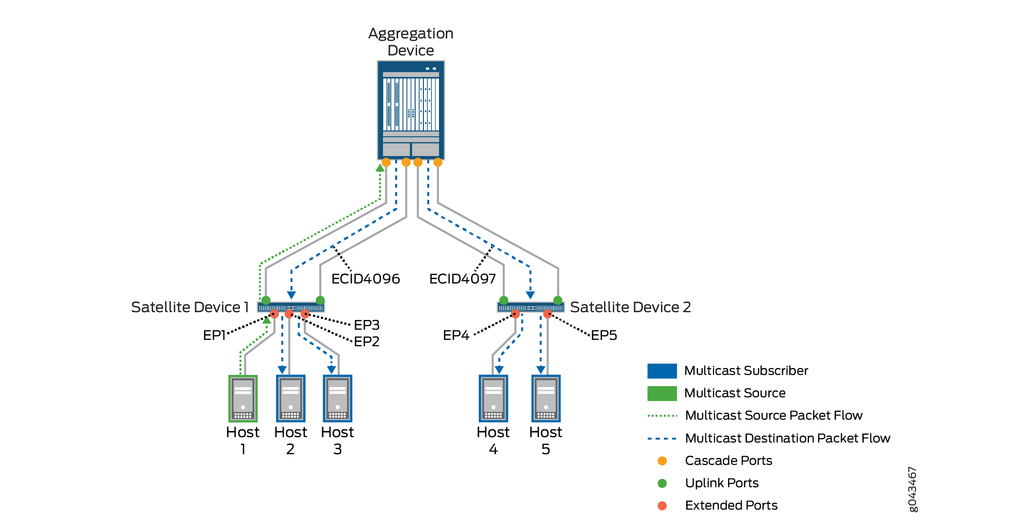
A data packet is received from a multicast source on an extended port, EP1, with traffic destined for endpoints connected to extended ports EP2 through EP5. The aggregation device acquires multicast ECIDs from the satellite devices, which represent a set of multicast destination extended ports on each satellite device. The diagram shows ECID value ECID4096 is assigned to the multicast subscribers behind extended ports EP2 and EP3 on satellite device 1, and ECID4097 is assigned to the multicast subscribers behind extended ports EP4 and EP5 on satellite device 2. The aggregation device creates only one copy of the source packet for each satellite device that has multicast destination extended ports, inserts the corresponding satellite device multicast ECID value in the IEEE 802.1BR ETAG header of each copy, and forwards the copies to those satellite devices.
In this case, the aggregation device creates two copies, forwards one with ECID4096 to satellite device 1, and forwards the other with ECID4097 to satellite device 2. Each satellite device receives its copy and uses the multicast ECID value to determine which of its extended ports should receive the multicast traffic. Satellite device 1 replicates the packet and forwards copies to EP2 and EP3; satellite device 2 replicates the packet and forwards copies to EP4 and EP5.
When forwarding replicated multicast packets to satellite devices, the aggregation device resolves the next-hop path through a corresponding cascade port that reaches the satellite device. When there are multiple cascade port links to a satellite device, the aggregation device load-balances the traffic when choosing which cascade port to use.
Other multicast destinations might be reached through ports on the aggregation devices, rather than through extended ports. For these destinations, the aggregation device creates and sends copies to those local ports directly.
Local Replication for VLAN Flooding
An aggregation device might initiate VLAN flooding (broadcasting or flooding the packet out to all interfaces in the VLAN) to learn the MAC address for a destination that is not already in its Ethernet switching tables. When local replication is not enabled, the aggregation device uses ingress replication, creating and sending copies to each destination extended port on each satellite device that has destination extended ports in the VLAN. With local replication enabled, the aggregation device requests multicast ECIDs to represent the extended ports in the VLAN on each satellite device. The aggregation device sends a copy of the source packet tagged with each ECID in the IEEE 802.1BR header to the corresponding satellite device. Each receiving satellite device does the replication locally for its extended ports in the VLAN.
Figure 2 illustrates the packet flow for VLAN flooding when local replication is enabled.
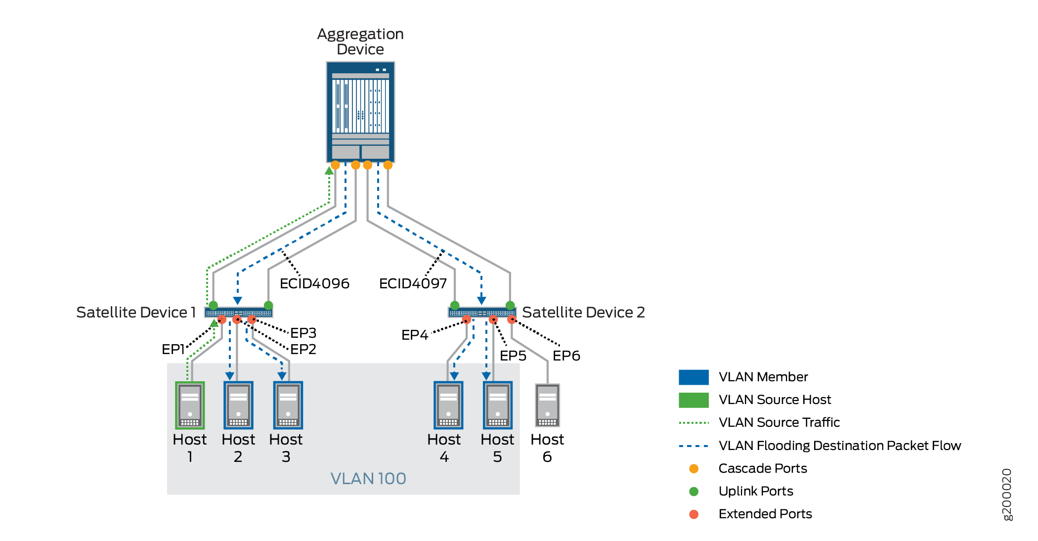
In this example, a multicast source packet for VLAN 100 ingresses on EP1, and satellite device 1 forwards the packet to the aggregation device. The aggregation device cannot resolve the destination MAC address, and decides to flood the packet to all extended port destinations in VLAN 100.
When a source packet ingresses at a satellite device with uplink ports to dual aggregation devices, the satellite device load-balances forwarding the ingress traffic among the available uplink ports, so either aggregation device might receive the source packet and manage flooding the packet to destination VLAN members.
Multicast ECID4096 is allocated to represent extended ports on satellite device 1 that are members of VLAN 100—EP1, EP2 and EP3, and multicast ECID4097 represents extended ports on satellite device 2 that are also members of VLAN 100—EP4 and EP5. Host 6 behind extended port EP6 is not a member of VLAN 100 and is not a destination for the flooded traffic. The aggregation device creates one copy of the packet tagged with ECID4096 and sends it to satellite device 1, and sends one copy tagged with ECID4097 to satellite device 2. Satellite device 1 replicates and forwards the packet for its own destination ports in VLAN 100, EP2 and EP3. (The ingress ECID split-horizon mechanism prevents forwarding traffic to the ingress port, EP1.) Satellite device 2 replicates and forwards the packet for EP4 and EP5, its local destination ports in VLAN 100. The extended port mapping for ECID4097 does not include EP6, so satellite device 2 does not forward the packet to that port.
When there are multiple cascade port links to a satellite device, the aggregation device load-balances the traffic when choosing which cascade port to use.
For destination VLAN members reachable through aggregation device ports (rather than extended ports), the aggregation device creates and sends copies to those local ports directly.
Local Replication for Layer 3 Multicast Traffic Over IRB Interfaces
Integrated Routing and Bridging (IRB) provides support for Layer 2 bridging and Layer 3 routing on the same interface, and IRB interfaces are used to route traffic between VLANs. Because satellite devices do not maintain Layer 3 routing information, local replication on the satellite devices only occurs for Layer 2 traffic, and the aggregation device manages the replication of multicast destination packets at Layer 3.
In Junos Fusion Enterprise or Junos Fusion Provider Edge architectures, the aggregation device forwarding the traffic replicates the multicast source packet for each IRB interface in the Layer 3 replication list for a multicast group, and performs a VLAN tag rewrite for each corresponding VLAN. When there are extended ports in multiple VLANs on a satellite device that are receivers in the same multicast group, the aggregation device sends copies to each IRB with its corresponding VLAN ID to that satellite device. If an IRB interface (VLAN membership) spans multiple satellite devices, the aggregation device creates and sends one copy to each satellite device that has multicast receivers that are members of that VLAN. Each satellite device then replicates and forwards copies of the received packet for its local multicast destination extended ports.
Figure 3 shows an example of Layer 3 multicast replication for VLANs over IRB interfaces in a Junos Fusion. In this case, two VLANs with corresponding IRB interfaces are configured on the aggregation device. In this case, multicast source packets ingress on an aggregation device port, and multicast subscribers are connected to extended ports EP1 through EP5, where extended ports EP1 and EP2 are in VLAN 100 and EP3 through EP5 are in VLAN 200.
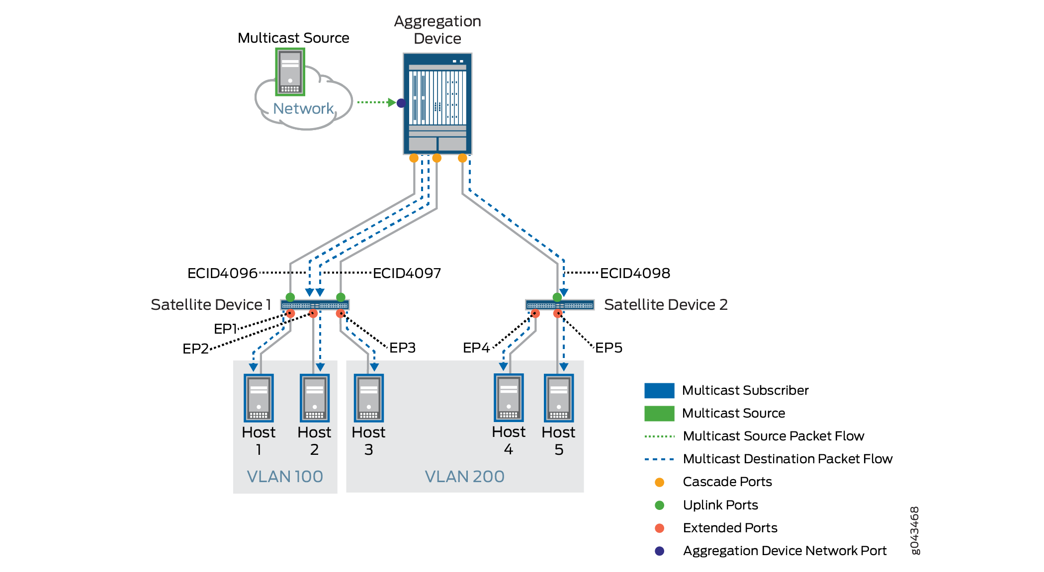
When the aggregation device receives a packet from the multicast source, it manages the Layer 3 replication by acquiring multicast ECIDs representing the destination extended ports in each VLAN on each satellite device, and creating, tagging, and forwarding copies on each VLAN’s IRB interface to the satellite devices that have destination extended ports. As the figure shows, the aggregation device creates 3 copies of the source packet, as follows:
-
Multicast ECID4096 represents EP1 and EP2 in VLAN 100 on satellite device 1. The aggregation device forwards one copy tagged with ECID4096 to satellite device 1 for the VLAN 100 IRB interface.
-
Multicast ECID4097 represents EP3 in VLAN 200 on satellite device 1. The aggregation device forwards a second copy tagged with ECID4097 to satellite device 1 for the VLAN 200 IRB interface.
-
Multicast ECID4098 represents EP4 and EP5 in VLAN 200 on satellite device 2. The aggregation device forwards a third copy tagged with ECID4098 for the VLAN 200 IRB interface to satellite device 2.
Each satellite device manages the Layer 2 processing by replicating the packets received from the aggregation device for the multicast subscribers behind its extended ports in each VLAN, as follows:
-
Satellite device 1 replicates and forwards packets tagged with ECID4096 to extended ports EP1 and EP2, and forwards packets tagged with ECID4097 to EP3.
-
Satellite device 2 replicates and forwards the packets tagged with ECID4096 to extended ports EP4 and EP5.
When there are multiple cascade port links to a satellite device, the aggregation device load-balances the traffic when choosing which cascade port to use.
For multicast destination VLAN members reachable through aggregation device ports (rather than extended ports), the aggregation device creates and sends copies to those local ports using the corresponding IRB interfaces.