Understanding CoS in Junos Fusion Enterprise
Junos Fusion provides a method of significantly expanding the number of available network interfaces on an aggregation device by allowing the aggregation device to add interfaces through interconnections with satellite devices. The entire system—the interconnected aggregation device and satellite devices—is called Junos Fusion. Junos Fusion simplifies network administration by appearing in the network topology as a single device, and the single device is managed from a single IP address.
See Figure 1 and Figure 2 for illustrations of the Junos Fusion Enterprise topology.
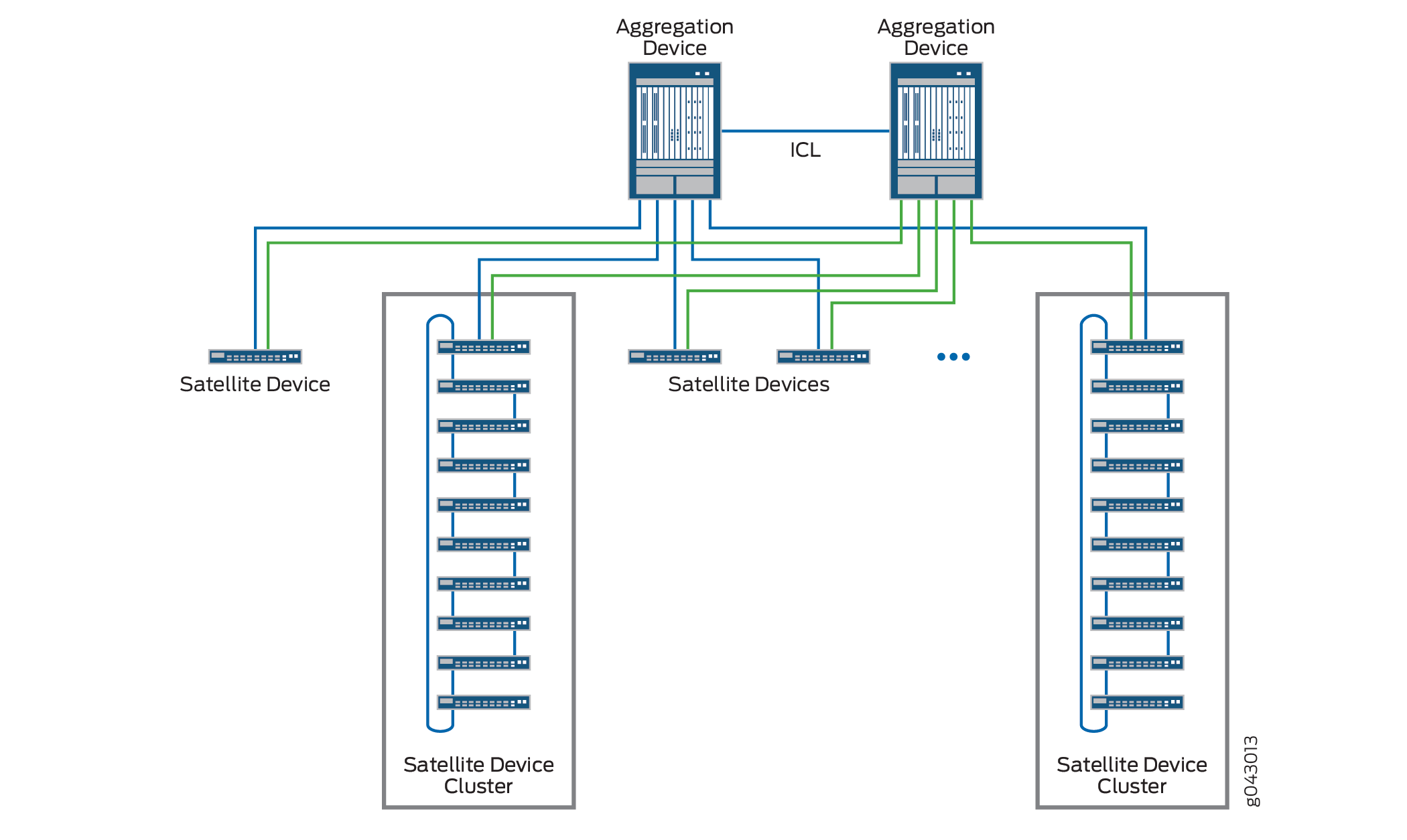
For Junos Fusion Enterprise, an aggregation device is an EX9200 switch that is running Junos OS Release 16.1R1 or later. Beginning with Junos OS Release 17.1R1, Junos Fusion Enterprise supports CoS. CoS configuration is the same on Junos Fusion Enterprise regardless of the selected architecture - single or dual aggregation devices, single or cluster satellite devices.
This topic describes class of service (CoS) on the different types of ports in Junos Fusion.
This topic covers:
Overview of CoS on Different Types of Ports in Junos Fusion
Figure 3 provides an overview of packet flow through Junos Fusion and how CoS features are applied at the different ports.
All configuration for CoS policies for Junos Fusion is done on the aggregation device. For CoS policies that you define for extended ports, however, different portions of that policy are applied at different points in a packet’s path through Junos Fusion. From Figure 3:
As a packet enters an extended port, any port-level (physical interface-level) behavior aggregate (BA) classifier you define for that port is applied to derive a forwarding class and packet loss priority.
As that packet exits the uplink port, you can apply schedulers or enhanced transmission selection (ETS) based on the port-level BA classifier assigned at the ingress extended port.
As the packet enters the aggregation device at the cascade port, any multifield classifiers, policers, or logical interface-level BA classifiers you define for the ingress extended port are applied.
As the packet exits the aggregation device at the cascade port, any rewrite rules you define for the egress extended port, as well as any schedulers you define for the cascade port, are applied. Also, the forwarding class determined in the previous step is carried in the 801.2BR header to the satellite device and used to select the output queue at the egress extended port.
Finally, as the packet exits an extended port, any schedulers or ETS you define for that port are applied based on the forwarding class determined by the multifield classifiers, policers, or logical interface-level BA classifiers defined for the ingress extended port.
The following sections provide further information about implementing CoS on each port type in Junos Fusion.
CoS on Extended Ports and Uplink Ports in Junos Fusion
All class of service (CoS) scheduling policies for extended ports and uplink ports on the satellite devices are provisioned on the EX9200 aggregation device. Similarly, standard Junos OS CoS commands are issued on the EX9200 aggregation device for retrieving extended port and uplink port CoS states and queue statistics. The EX9200 aggregation device supports configuring the following CoS features for each extended port and uplink port on each satellite device:
Behavior aggregate classifiers
Multifield classifiers
Input and output policers
Forwarding classes
Traffic control profiles
Schedulers and scheduler maps
Egress rewrite rules
Configuring CoS policies on satellite devices (on both extended and uplink ports) has the following restrictions:
IP precedence classifiers are not supported. DSCP classifiers are supported, however.
Interpolated drop profiles are not supported.
The
transmit-rateoption is supported for schedulers. However, theremainder,rate-limit, andexactoptions are not supported undertransmit-rate.
While CoS features for satellite device ports are configured on the aggregation device, the actual classification, queueing, and scheduling is performed on the satellite devices. Information on actual traffic shaping is not passed back to the aggregation device. Logical interface statistics for the show interfaces command are collected on the aggregate device and do not include shaping rate data. For actual traffic statistics gathered on satellite device interfaces, use the statistics for the physical interface and not the logical interface.
CoS statistics are not supported on extended ports.
CoS on Cascade Ports in Junos Fusion
When a cascade port is created, two logical interfaces are automatically created:
One in-band management logical interface (assigned unit 32769) for traffic that only flows between the aggregation device and the satellite devices, such as keepalives, for provisioning information, and for software updates.
One for data logical interface (assigned unit 32770) for regular traffic that flows into and out of Junos Fusion.
Per-unit scheduling is automatically enabled on the cascade port to support multiple queues on each of the logical interfaces.
All cascade ports must be configured on Modular Port Concentrators (MPCs) that support per-unit scheduling.
50 Mbps of bandwidth is reserved for the management logical interface. The remaining bandwidth is available to the data logical interface. A shaping rate of 10 percent is also applied to the management logical interface, which means it can use up to 10 percent of the full interface bandwidth, if available.
The default scheduling policy is applied to the data logical interface. This reserves 95 percent of the available bandwidth and buffer space for the best effort forwarding class (mapped to queue 0) and 5 percent for the network control forwarding class (mapped to queue 3). You can create custom forwarding classes and schedulers by applying a custom scheduler map to this logical interface.
Change History Table
Feature support is determined by the platform and release you are using. Use Feature Explorer to determine if a feature is supported on your platform.