Traffic Processing on SRX Series Firewalls Overview
Junos OS for security devices integrates network security and routing capabilities of Juniper Networks. Packets that enter and exit a device undergo both packet-based and flow-based processing.
Understanding Traffic Processing on Security Devices
Junos OS for security devices integrates the world-class network security and routing capabilities of Juniper Networks. Junos OS includes a wide range of packet-based filtering, class-of-service (CoS) classifiers, and traffic-shaping features as well as a rich, extensive set of flow-based security features including policies, screens, network address translation (NAT), and other flow-based services.
Traffic that enters and exits a security device is processed according to features you configure, such as packet filters, security policies, and screens. For example, the software can determine:
Whether the packet is allowed into the device
Which firewall screens to apply to the packet
The route the packet takes to reach its destination
Which CoS to apply to the packet, if any
Whether to apply NAT to translate the packet’s IP address
Whether the packet requires an Application Layer Gateway (ALG)
Packets that enter and exit a device undergo both packet-based and flow-based processing:
Flow-based packet processing treats related packets, or a stream of packets, in the same way. Packet treatment depends on characteristics that were established for the first packet of the packet stream, which is referred to as a flow.
For the distributed processing architecture of the services gateway, all flow-based processing occurs on the SPU and sampling is multi-thread aware. Packet sequencing is maintained for the sampled packets.
Packet-based, or stateless, packet processing treats packets discretely. Each packet is assessed individually for treatment.
For the distributed processing architecture of the services gateway, some packet-based processing, such as traffic shaping, occurs on the NPU. Some packet-based processing, such as application of classifiers to a packet, occurs on the SPU.
This topic includes the following sections:
Understanding Flow-Based Processing
A packet undergoes flow-based processing after packet-based filters and some screens have been applied to it. All flow-based processing for a single flow occurs on a single Services Processing Unit (SPU). An SPU processes the packets of a flow according to the security features and other services configured for the session.
Figure 1 shows a conceptual view of how flow-based traffic processing occurs on services gateway.
A flow is a stream of related packets that meet the same matching criteria and share the same characteristics. Junos OS treats packets belonging to the same flow in the same manner.
Configuration settings that determine the fate of a packet—such as the security policy that applies to it, if it requires an Application Layer Gateway (ALG), if NAT is applied to translate the packet’s source and/or destination IP address—are assessed for the first packet of a flow.
To determine if a flow exists for a packet, the NPU attempts to match the packet’s information to that of an existing session based on the following match criteria:
Source address
Destination address
Source port
Destination port
Protocol
Unique session token number for a given zone and virtual router
Zones and Policies
The security policy to be used for the first packet of a flow is cached in a flow table for use with the same flow and closely related flows. Security policies are associated with zones. A zone is a collection of interfaces that define a security boundary. A packet’s incoming zone, as determined by the interface through which it arrived, and its outgoing zone, as determined by the forwarding lookup, together determine which policy is used for packets of the flow.
Flows and Sessions
Flow-based packet processing, which is stateful, requires the creation of sessions. A session is created for the first packet of a flow for the following purposes:
To store most of the security measures to be applied to the packets of the flow.
To cache information about the state of the flow.
For example, logging and counting information for a flow is cached in its session. (Some stateful firewall screens rely on threshold values that pertain to individual sessions or across all sessions.)
To allocate required resources for the flow for features such as NAT.
To provide a framework for features such as ALGs and firewall features.
Most packet processing occurs in the context of a flow, including:
Management of policies, NAT, zones, and most screens.
Management of ALGs and authentication.
Understanding Packet-Based Processing
A packet undergoes packet-based processing when it is removed from the queue on its input interface and before it is added to the queue on its output interface.
Packet-based processing applies stateless firewall filters, CoS features, and some screens to discrete packets.
When a packet arrives at an interface, sanity checks, packet-based filters, some CoS features, and some screens are applied to it.
Before a packet leaves the device, any packet-based filters, some CoS features, and some screens associated with the interface are applied to the packet.
Filters and CoS features are typically associated with one or more interfaces to influence which packets are allowed to transit the system and to apply special actions to packets as necessary.
The following topics describe the kinds of packet-based features that you can configure and apply to transit traffic.
Stateless Firewall Filters
Also referred to as access control lists (ACLs), stateless firewall filters control access and limit traffic rates. They statically evaluate the contents of packets transiting the device from a source to a destination, or packets originating from or destined for the Routing Engine. A stateless firewall filter evaluates every packet, including fragmented packets.
You can apply a stateless firewall filter to an input or output interface, or to both. A filter contains one or more terms, and each term consists of two components—match conditions and actions. By default, a packet that does not match a firewall filter is discarded.
You can plan and design stateless firewall filters to be used for various purposes—for example, to limit traffic to certain protocols, IP source or destination addresses, or data rates. Stateless firewall filters are executed on the NPU.
Class-of-Service Features
CoS features allow you to classify and shape traffic. CoS features are executed on the NPU.
Behavior aggregate (BA) classifiers—These classifiers operate on packets as they enter the device. Using behavior aggregate classifiers, the device aggregates different types of traffic into a single forwarding class to receive the same forwarding treatment. BA classifiers allow you to set the forwarding class and loss priority of a packet based on the Differentiated Service (DiffServ) value.
Traffic shaping—You can shape traffic by assigning service levels with different delay, jitter, and packet loss characteristics to particular applications served by specific traffic flows. Traffic shaping is especially useful for real-time applications, such as voice and video transmission.
Screens
Some screens, such as denial-of-service (DoS) screens, are applied to a packet outside the flow process. They are executed on the Network Processing Unit (NPU).
Understanding the Default Processing Behavior for IPv4 Traffic
Flow-based processing mode is required for security features such as zones, screens, and firewall policies to function. For drop mode processing, the traffic is dropped directly, it is not forwarded. It differs from packet-mode processing for which the traffic is handled but no security processes are applied.
Use Feature Explorer to confirm platform and release support for specific features.
Review the Understanding the Default Processing Behavior for IPv4 Traffic section for notes related to your platform.
Configuring an SRX Series Device as a Border Router
When an SRX Series Firewall of any type is enabled for flow-based processing or drop mode, to
configure the device as a border router you must change the mode to packet-based
processing for MPLS. In this case, to configure the SRX Series Firewall to packet mode
for MPLS, use the set security forwarding-options family mpls mode
packet-based statement.
Platform-Specific IPv4 Traffic Behavior
Use Feature Explorer to confirm platform and release support for specific features.
Use the following table to review platform-specific behavior for your platform:
|
Platform |
Difference |
|---|---|
|
SRX Series Firewall |
|
Understanding Traffic Processing on SRX320 Devices
This topic describes the process that the SRX320 Services Gateways undertake in establishing a session for packets belonging to a flow that transits the device. The flow services of the SRX320 devices are single-threaded and non-distributed. Although they differ from the other SRX Series Firewalls in this respect, the same flow model is followed and the same command line interface (CLI) is implemented.
To illustrate session establishment and the packet “walk” including the points at which services are applied to the packets of a flow, the example described in the following sections uses the simple case of a unicast session:
- Understanding Flow Processing and Session Management
- Understanding First-Packet Processing
- Understanding Session Creation
- Understanding Fast-Path Processing
Understanding Flow Processing and Session Management
This topic explains how a session is set up to process the packets composing a flow. In the following topic, the SPU refers to the data plane thread of the SRX320 Firewall.
At the outset, the data plane thread fetches the packet and performs basic sanity checks on it. Then it processes the packet for stateless filters and CoS classifiers and applies some screens.
Understanding First-Packet Processing
To determine if a packet belongs to an existing flow, the device attempts to match the packet’s information to that of an existing session based on the following six match criteria:
Source address
Destination address
Source port
Destination port
Protocol
Unique token from a given zone and virtual router
The SPU checks its session table for an existing session for the packet. If no existent session is found, the SPU sets up a session for the flow. If a session match is found, the session has already been created, so the SPU performs fast-path processing on the packet.
Understanding Session Creation
In setting up the session, the SPU executes the following services for the packet:
Screens
Route lookup
Policy lookup
Service lookup
NAT, if required
After a session is set up, it is used for all packets belonging to the flow. Packets of a flow are processed according to the parameters of its session. For the remainder of the steps entailed in packet processing, proceed to Step 1 in “Fast-Path Processing”. All packets undergo fast-path processing.
Understanding Fast-Path Processing
If a packet matches a session, Junos OS performs fast-path processing as described in the following steps. After a session has been set up for the first packet in a flow, also undergoes fast-path processing. All packets undergo fast-path processing.
The SPU applies flow-based security features to the packet.
Configured screens are applied.
TCP checks are performed.
Flow services, such as NAT, ALG, and IPsec are applied, if required.
The SPU prepares the packet for forwarding and transmits it.
Routing packet filters are applied.
Traffic shaping is applied.
Traffic prioritizing is applied.
Traffic scheduling is applied.
The packet is transmitted.
Understanding Traffic Processing on SRX4600 Devices
The Juniper Networks SRX4600 Firewall integrates flow-based security and routing services, including advanced security and threat mitigation and traditional stateful firewall security. The Junos OS flow-based infrastructure provides the foundation and framework for Layer 4 through Layer 7 application-based services. The SRX4600 Firewall is designed to be deployed as an integrated firewall at the large enterprise data center edge and data center core, and the campus edge. It can also be deployed as an LTE security gateway and a Gi/SGi firewall.
This topic includes the following content:
- Understanding Deployment Scenarios for the SRX4600 Firewall and Its Features
- Flow-Based Processing and Session Fundamentals
- Flow and Session Underlying Components Implemented Across SRX Series Firewalls
Understanding Deployment Scenarios for the SRX4600 Firewall and Its Features
The SRX4600 Firewall can be deployed in many areas to secure your environment and its resources. It is often used to protect the data center edge and core in the following ways:
-
Deploying the SRX4600 Firewall as a Data Center Edge Firewall
You can deploy the SRX4600 Firewall at the edge of your data center to provide the applications and services that it hosts with optimum protection. Every data center has an ingress point to allow clients access to the data center’s services, but malicious aggressors can take advantage of it to launch attacks against these services. A large amount of traffic coming into the data center is ingress internet traffic. For that reason alone, deploying robust, multi-layered security at the data center edge is essential. The SRX4600 Firewall effectively and reliantly blocks attacks, and it allows you to configure the system to thwart specific kinds of attacks. The SRX4600 Firewall supports Juniper’s Software-Defined Secure Network (SDSN) framework, including Juniper Advanced Threat Prevention Cloud (ATP Cloud), which is built around automated and actionable intelligence that can be shared quickly to recognize and mitigate threats. Figure 2 shows the SRX4600 Firewall deployed at the data center edge in conjunction with an MX480 router and EX Series switches.
Figure 2: Deploying the SRX4600 Firewall at the Data Center Edge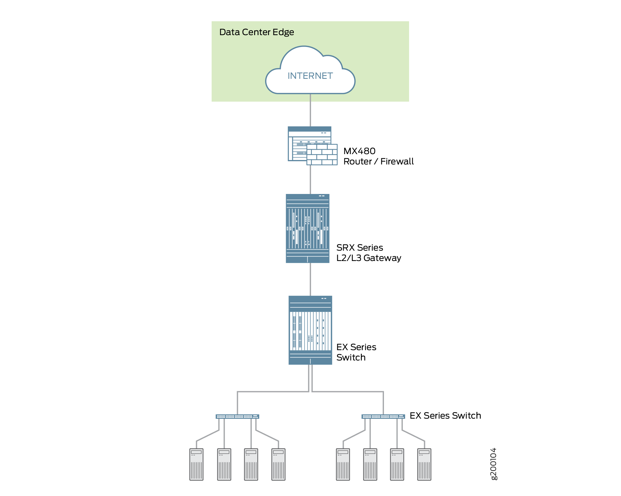
-
Deploying the SRX4600 Firewall at the Data Center Core
You can deploy the SRX4600 Firewall at the data center core to provide enhanced security and to ensure that compliance requirements are met. Data center processing has become increasingly dynamic necessitating clear network definition and compliance requirements enforcement. To ensure compliance, you can use the SRX4600 Firewall to segment your overall network into individual server networks and secure traffic within them. The SRX4600 Firewall provides high availability and automation, and its high performance Layer 3 and Layer 4 services meet the security requirements of the data center core. Figure 3 shows the SRX4600 Firewall deployed as a multi-layered firewall at the data center core.
Figure 3: Deploying the SRX4600 Firewall at the Data Center Core
In addition to its advanced anti-malware features, the SRX4600 Firewall supports the following features:
-
Stateful firewall
-
Application security suite
-
Content Security (Sophos AV, Web filtering, antispam)
-
IDP
-
High availability (Chassis cluster)
-
Dual HA control ports (10G)
-
MACsec support for HA ports
-
-
Ethernet interfaces through QSFP28 (100G/40G/4x10G modes), QSFP+ (40G/4x10G modes) and SFP+ (10G mode)
-
IPsec VPN, including AutoVPN and Group VPNv2
-
QoS and network services
-
J-Web
-
Routing policies with multicast
Flow-Based Processing and Session Fundamentals
To understand flow processing on the SRX4600 Firewall, it is important to understand the fundamentals of flow.
A flow is a stream of related packets that meet the same matching criteria and share the same characteristics. Junos OS treats packets that belong to the same flow in the same way. The architecture of an SRX Series services gateway and how it handles packet flows are tightly coupled. Consequently, in part, flow is implemented differently across the family of SRX Series Firewalls because of their architectural differences.
Flow-based packet processing, which is stateful, requires the creation of sessions. Sessions are created based on routing and other traffic classification information to store information and allocate resources for a flow. Sessions cache information about the state of the flow, and they store most of the security measures to be applied to packets of the flow. Because of the architectural differences across devices, sessions are also managed differently by different devices.
Regardless of these differences, conceptually the flow process is the same across all services gateways, and sessions serve the same purposes and have the same features.
Flow and Session Underlying Components Implemented Across SRX Series Firewalls
SRX Series Firewalls use the same infrastructure components to support flow and manage sessions, but not all devices implement all of them.
To understand flow, it is essential to understand the following components and how they are used:
-
The Services Processing Unit (SPU)
An SPU manages the session for a packet flow. It applies security features and other services to the packet. It also applies packet-based stateless firewall filters, classifiers, and traffic shapers to the packet.
-
The central point (CP)
The central point is an SPU that the system uses to allocate resources and distribute session management among SPUs. When the first packet of a flow is processed, the central point determines which SPU to use for that packet’s session. The SRX4600 Firewall does not implement a central point.
-
The Network Processing Unit (NPU) and the Network Processing session
An NPU is a processor that runs on an I/O card (IOC) and processes packets discretely. When a flow is created, subsequent packets of the flow are matched to the session on the NPU. The NPU handles additional processing such as TCP sequence check, time-to-live (TTL) processing, and Layer 2 header translation. An NPU improves performance in that extra packet forwarding between a session-SPU and a hash-SPU is avoided. The SRX4600 Firewall implements an NPU.
The SRX4600 Firewall flow architecture has been improved to optimize use of the SRX4600 device’s advanced multi-core Xeon™ Processors. The SRX4600 Firewall implements the use of a dedicated session thread to circumvent problems such as management of out-of-order packets in a flow. It utilizes the network processing session to ensure that packets are forwarded to the right, dedicated thread. Packets are distributed to different threads in accord with the hash-based session distribution model.
Understanding Traffic Processing on SRX5000 Line Devices
Junos OS on SRX5000 devices is a distributed, parallel processing, high-throughput and high-performance system. The distributed parallel processing architecture of the SRX5000 line of services gateways includes multiple processors to manage sessions and run security and other services processing. This architecture provides greater flexibility and allows for high throughput and fast performance.
In SRX1400, SRX3400, SRX3600, SRX5400, SRX5600, and SRX5800 devices, IKE negotiations involving NAT traversal do not work if the IKE peer is behind a NAT device that will change the source IP address of the IKE packets during the negotiation. For example, if the NAT device is configured with DIP, it changes the source IP because the IKE protocol switches the UDP port from 500 to 4500.
The I/O cards (IOCs) and Services Processing Cards (SPCs) on SRX5000 line devices contain processing units that process a packet as it traverses the device. An IOC has one or more Network Processing Units (NPUs), and a SPC has one or more Services Processing Units (SPUs).
These processing units have different responsibilities. All flow-based services for a packet are executed on a single SPU. The responsibilities of these NPUs are not clearly delineated in regard to the other kind of services that run on them. .)
For example:
-
An NPU processes packets discretely. It performs sanity checks and applies some screens that are configured for the interface, such as denial-of-service (DoS) screens, to the packet.
-
An SPU manages the session for the packet flow and applies security features and other services to the packet. It also applies packet-based stateless firewall filters, classifiers, and traffic shapers to the packet.
-
An NPU forwards a packet to the SPU using the hash algorithm. However, for some applications, like ALG, the system will need to query the application central point to determine on which SPU the packet should be processed.
These discrete, cooperating parts of the system, including the central point, each store the information identifying whether a session exists for a stream of packets and the information against which a packet is matched to determine if it belongs to an existing session.
This architecture allows the device to distribute processing of all sessions across multiple SPUs. It also allows an NPU to determine if a session exists for a packet, to check the packet, and to apply screens to the packet. How a packet is handled depends on whether it is the first packet in a flow.
The following sections describe the processing architecture using SRX5400, SRX5600, and SRX5800 devices as an example:
- Understanding First-Packet Processing
- Understanding Fast-Path Processing
- Understanding the Data Path for Unicast Sessions
- Understanding Services Processing Units
- Understanding Scheduler Characteristics
- Understanding Network Processor Bundling
Understanding First-Packet Processing
Figure 4 illustrates the path the first packet in a flow takes as it enters the device—the NPU determines that no session exists for the packet, and the NPU sends the packet to the distributed central point to set up a distributed central point session. The distributed central point then sends a message to the application central point to select the SPU to set up a session for the packet and to process the packet. The distributed central point then sends the packet to that SPU. The SPU processes the packet and sends it to the NPU for transmission from the device. (This high-level description does not address application of features to a packet.)
After the first packet in a flow has traversed the system and a session has been established for it, it undergoes fast-path processing.
Subsequent packets in the flow also undergo fast-path processing; in this case, after each packet enters the session and the NPU finds a match for it in its session table, the NPU forwards the packet to the SPU that manages its session.
Figure 5 illustrates fast-path processing. This is the path a packet takes when a flow has already been established for its related packets. (It is also the path that the first packet in a flow takes after the session for the flow that the packet initiated has been set up.) After the packet enters the device, the NPU finds a match for the packet in its session table, and it forwards the packet to the SPU that manages the packet’s session. Note that the packet bypasses interaction with the central point.
Understanding Fast-Path Processing
The following section explains how a session is created and the process a packet undergoes as it transits the device.
Here is an overview of the main components involved in setting up a session for a packet and processing packets both discretely and as part of a flow as they transit the SRX5400, SRX5600, and SRX5800 devices.
-
Network Processing Units (NPUs)—NPUs reside on IOCs. They handle packet sanity checking and application of some screens. NPUs maintain session tables that they use to determine if a session exists for an incoming packet or for reverse traffic.
The NPU session table contains an entry for a session if the session is established on an SPU for a packet that had previously entered the device via the interface and was processed by this NPU. The SPU installs the session in the NPU table when it creates the session.
An NPU determines if a session exists for a packet by checking the packet information against its session table. If the packet matches an existing session, the NPU sends the packet and the metadata for it to the SPU. If there is no session, the NPUs sends the packet to one SPU which is calculated using the hash algorithm.
-
Services Processing Units (SPUs)—The main processors of the SRX5400, SRX5600, and SRX5800 devices reside on SPCs. SPUs establish and manage traffic flows and perform most of the packet processing on a packet as it transits the device. Each SPU maintains a hash table for fast session lookup. The SPU applies stateless firewall filters, classifiers, and traffic shapers to traffic. An SPU performs all flow-based processing for a packet and most packet-based processing. Each multicore SPU processes packets independently with minimum interaction among SPUs on the same or different SPC. All packets that belong to the same flow are processed by the same SPU.
The SPU maintains a session table with entries for all sessions that it established and whose packets it processes. When an SPU receives a packet from an NPU, it checks its session table to ensure that the packet belongs to it. It also checks its session table when it receives a packet from the distributed central point and sends a message to establish a session for that packet to verify that there is not an existing session for the packet.
-
Central point—The central point architecture is divided into two modules, the application central point and the distributed central point. The application central point is responsible for global resource management and loading balancing, while the distributed central point is responsible for traffic identification (global session matching). The application central point functionality runs on the dedicated central point SPU, while the distributed central point functionality is distributed to the rest of the SPUs. Now the central point sessions are no longer on the dedicated central point SPU, but with the distributed central point on other flow SPUs.
-
Routing Engine—The Routing Engine runs the control plane.
Understanding the Data Path for Unicast Sessions
This section describes the process of establishing a session for packets belonging to a flow that transits the device.
To illustrate session establishment and the packet “walk” including the points at which services are applied to the packets in a flow, this example uses the simple case of a unicast session.
This packet “walk” brings together the packet-based processing and flow-based processing that Junos OS performs on the packet.
- Session Lookup and Packet-Match Criteria
- Understanding Session Creation: First-Packet Processing
- Understanding Fast-Path Processing
Session Lookup and Packet-Match Criteria
To determine if a packet belongs to an existing flow, the device attempts to match the packet’s information to that of an existing session based on the following six match criteria:
-
Source address
-
Destination address
-
Source port
-
Destination port
-
Protocol
-
Unique token from a given zone and virtual router
Understanding Session Creation: First-Packet Processing
This section explains how a session is set up to process the packets composing a flow. To illustrate the process, this section uses an example with a source “a” and a destination “b”. The direction from source to destination for the packets of the flow is referred to as (a ->b). The direction from destination to source is referred to as (b->a).
Step 1. A Packet Arrives at an Interface on the Device And the NPU Processes It.
This section describes how a packet is handled when it arrives at an SRX Series Firewall ingress IOC.
-
The packet arrives at the device’s IOC and is processed by the NPU on the IOC.
-
The NPU performs basic sanity checks on the packet and applies some screens configured for the interface to the packet.
-
The NPU checks its session table for an existing session for the packet. (It checks the packet’s tuple against those of packets for existing sessions in its session table.)
-
If no existing session is found, the NPU forwards the packet to the hash SPU.
-
If a session match is found, the session has already been created on an SPU that was assigned to it, so the NPU forwards the packet to the SPU for processing along with the session ID.
-
Example: Packet (a ->b) arrives at NPU1. NPU1 performs sanity checks and applies DoS screens to the packet. NPU1 checks its session table for a tuple match, and no existing session is found. NPU1 forwards the packet to an SPU.
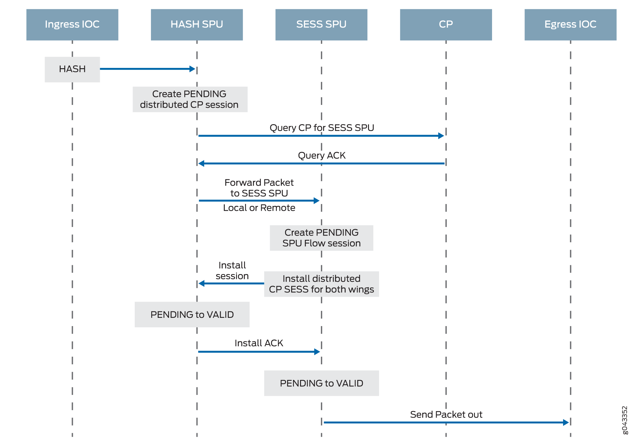
Step 2. The Distributed Central Point Creates a Session with a "Pending” State.
When an NPU receives a packet, the NPU send it to the distributed central point, based on the hash algorithm. The distributed central point then looks up the distributed central point session table and creates an entry if needed.
This process entails the following parts:
-
The distributed central point checks its session table to determine if a session exists for the packet received from the NPU. (An NPU forwards a packet to the distributed central point because it cannot find an existing session for the packet)
-
If there is no entry that matches the packet in the distributed central point session table, the distributed central point creates a pending wing for the session. The distributed central point then sends a query message to the application central point to select an SPU to be used for the session.
-
On receiving the query message, the application central point checks its gate table to determine if a gate exists for the packet. If a gate is matched or some other session distribution algorithm is triggered, the application central point selects another SPU to process the packet; otherwise, the SPU (that is, the distributed central point SPU) is selected. Finally, the application central point sends a query response to the distributed central point.
-
On receiving the query response, the distributed central point forwards the first packet in flow to the selected SPU in a message directing the SPU to set up a session locally to be used for the packet flow. For example, the distributed central point creates a pending wing (a ->b) for the session. The application central point selects SPU1 to be used for it. The distributed central point sends SPU1 the (a->b) packet along with a message to create a session for the distributed central point.
Example: The distributed central point creates a pending wing (a ->b) for the session. It selects SPU1 to be used for it. It sends SPU1 the (a->b) packet along with a message to create a session for it.
Step 3. The SPU Sets Up the Session.
Each SPU, too, has a session table, which contains information about its sessions. When the SPU receives a message from the distributed central point to set up a session, it checks its session table to ensure that a session does not already exist for the packet.
-
If there is no existing session for the packet, the SPU sets up the session locally.
-
The SPU sends a message to the distributed central point directing it to install the session.
Note:During first-packet processing, if NAT is enabled, the SPU allocates IP address resources for NAT. In this case, the first-packet processing for the session is suspended until the NAT allocation process is completed.
The SPU adds to the queue any additional packets for the flow that it might receive until the session has been installed.
Example: SPU1 creates the session for (a ->b) and sends a message back to the distributed central point directing it to install the pending session.
Step 4. The Distributed Central Point Installs the Session.
The distributed central point receives the install message from the SPU.
-
The distributed central point sets the state for the session’s pending wing to active.
-
The distributed central point installs the reverse wing for the session as an active wing.
Note:For some cases, such as NAT, the reverse wing may be installed on a different distributed central point from the init wing distributed central point.
-
It sends an acknowledge (ACK) message to the SPU, indicating that the session is installed.
Example: The distributed central point receives a message from SPU1 to install the session for the (a->b) wing. It sets the session state for the (a->b) wing to active. It installs the reverse wing (b->a) for the session and makes it active; this allows for delivery of packets from the reverse direction of the flow: destination (b) to be delivered to the source (a).
Step 5. The SPU Sets Up the Session on the Ingress and Egress NPUs.
NPUs maintain information about a session for packet forwarding and delivery. Session information is set up on the egress and ingress NPUs (which sometimes are the same) so that packets can be sent directly to the SPU that manages their flows and not to the distributed central point for redirection.
Step 6. Fast-Path Processing Takes Place.
For the remainder of the steps entailed in packet processing, proceed to Step 1 in Understanding Fast-Path Processing.
Figure 6 illustrates the first part of the process that the first packet in a flow undergoes after it reaches the device. At this point a session is set up to process the packet and the rest of the packets belonging to its flow. Subsequently, it and the rest of the packets in the flow undergo fast-path processing.
Understanding Fast-Path Processing
All packets undergo fast-path processing. However, if a session exists for a packet, the packet undergoes fast-path processing and bypasses the first-packet process. When there is already a session for the packet’s flow, the packet does not transit the central point.
Here is how fast-path processing works: NPUs at the egress and ingress interfaces contain session tables that include the identification of the SPU that manages a packet’s flow. Because the NPUs have this session information, all traffic for the flow, including reverse traffic, is sent directly to that SPU for processing.
To illustrate the fast-path process, this section uses an example with a source “a” and a destination “b”. The direction from source to destination for the packets of the flow is referred to as (a->b). The direction from destination to source is referred to as (b->a).
Step 1. A Packet Arrives at the Device and the NPU Processes It.
This section describes how a packet is handled when it arrives at a services gateway’s IOC.
-
The packet arrives at the device’s IOC and is processed by the NPU on the card.
The NPU performs sanity checks and applies some screens, such as denial-of-service (DoS) screens, to the packet.
-
The NPU identifies an entry for an existing session in its session table that the packet matches.
-
The NPU forwards the packet along with metadata from its session table, including the session ID and packet tuple information, to the SPU that manages the session for the flow, applies stateless firewall filters and CoS features to its packets, and handles the packet’s flow processing and application of security and other features.
Example: Packet (a ->b) arrives at NPU1. NPU1 performs sanity checks on the packet, applies DoS screens to it, and checks its session table for a tuple match. It finds a match and that a session exists for the packet on SPU1. NPU1 forwards the packet to SPU1 for processing.
Step 2. The SPU for the Session Processes the Packet.
Most of a packet’s processing occurs on the SPU to which its session is assigned. The packet is processed for packet-based features such as stateless firewall filters, traffic shapers, and classifiers, if applicable. Configured flow-based security and related services such as firewall features, NAT, ALGs, and so on, are applied to the packet. (For information on how security services are determined for a session.
-
Before it processes the packet, the SPU checks its session table to verify that the packet belongs to one of its sessions.
-
The SPU processes the packet for applicable features and services.
Example: SPU1 receives packet (a->b) from NPU1. SPU1 checks its session table to verify that the packet belongs to one of its sessions. Then it processes packet (a ->b) according to input filters and CoS features that apply to its input interface. The SPU applies the security features and services that are configured for the packet’s flow to it, based on its zone and policies. If any are configured, it applies output filters, traffic shapers and additional screens to the packet.
Step 3. The SPU Forwards the Packet to the NPU.
-
The SPU forwards the packet to the NPU.
-
The NPU applies any applicable screens associated with the interface to the packet.
Example: SPU1 forwards packet (a ->b) to NPU2, and NPU2 applies DoS screens.
Step 4. The Interface Transmits the Packet from the Device.
Example: The interface transmits packet (a->b) from the device.
Step 5. A Reverse Traffic Packet Arrives at the Egress Interface and the NPU Processes It.
This step mirrors Step 1 exactly in reverse. See Step 1 in this section for details.
Example: Packet (b->a) arrives at NPU2. NPU2 checks its session table for a tuple match. It finds a match and that a session exists for the packet on SPU1. NPU2 forwards the packet to SPU1 for processing.
Step 6. The SPU for the Session Processes the Reverse Traffic Packet.
This step is the same as Step 2 except that it applies to reverse traffic. See Step 2 in this section for details.
Example: SPU1 receives packet (b->a) from NPU2. It checks its session table to verify that the packet belongs to the session identified by NPU2. Then it applies packet-based features configured for the NPU1’s interface to the packet. It processes packet (b->a) according to the security features and other services that are configured for its flow, based on its zone and policies.
Step 7. The SPU Forwards the Reverse Traffic Packet to the NPU.
This step is the same as Step 3 except that it applies to reverse traffic. See Step 3 in this section for details.
Example: SPU1 forwards packet (b->a) to NPU1. NPU1 processes any screens configured for the interface.
8. The Interface Transmits the Packet from the Device.
This step is the same as Step 4 except that it applies to reverse traffic. See Step 4 in this section for details.
Example: The interface transmits packet (b->a) from the device.
Figure 7 illustrates the process a packet undergoes when it reaches the device and a session exists for the flow that the packet belongs to.
Understanding Services Processing Units
For a given physical interface, the SPU receives ingress packets from all network processors in the network processor bundle associated with the physical interface. The SPU extracts network processor bundle information from the physical interface and uses the same 5-tuple hash algorithm to map a flow to a network processor index. To determine the network processor, the SPU does a lookup on the network processor index in the network processor bundle. The SPU sends egress packets to the physical interface’s local Physical Interface Module (PIM) for the outward traffic.
The network processor and the SPU use the same 5-tuple hash algorithm to get the hash values for the packets.
Understanding Scheduler Characteristics
For SRX5400, SRX5600, and SRX5800 devices, the IOC supports the following hierarchical scheduler characteristics:
-
IFL – The configuration of the network processor bundle is stored in the physical interface data structure. For example, SRX5400, SRX5600, and SRX5800 devices have a maximum of 48 PIMs. The physical interface can use a 48-bit bit-mask to indicate the PIM, or the network processor traffic from this physical interface is distributed in addition to the physical interface’s primary network processor.
On SRX5000 line devices, the iflset functionality is not supported for aggregated interfaces like reth.
-
IFD – The logical interface associated with the physical interface of a network processor bundle is passed to all the IOCs that have a PIM in the network processor bundle.
Understanding Network Processor Bundling
The network processor bundling feature is available on SRX5000 line devices. This feature enables distribution of data traffic from one interface to multiple network processors for packet processing. A primary network processor is assigned for an interface that receives the ingress traffic and distributes the packets to several other secondary network processors. A single network processor can act as a primary network processor or as a secondary network processor to multiple interfaces. A single network processor can join only one network processor bundle.
Network Processor Bundling Limitations
Network processor bundling functionality has the following limitations:
-
Network processor bundling allows a total of 16 PIMs per bundle and 8 different network processor bundle systems.
-
You need to reboot the device to apply the configuration changes on the bundle.
-
Network processor bundling is below the reth interface in the overall architecture. You can choose one or both interfaces from the network processor bundle to form the reth interface.
-
If the IOC is removed from a network processor bundle, the packets forwarded to the PIM on that IOC are lost.
-
When the network processor bundle is enabled, the ICMP, UDP, and TCP sync flooding thresholds no longer apply to an interface. Packets are distributed to multiple network processors for processing. These thresholds apply to each network processor in the network processor bundle.
-
Network processor bundling is not supported in Layer 2 mode.
-
Because of memory constraints on the network processor, the number of network processor bundled ports that are supported per PIM is limited. Within the network processor bundle, each port needs to have a global port index. The global port index is calculated using the following formula:
Global_port_index = (global_pic * 16) + port_offset
-
Link aggregation groups (LAGs) and redundant Ethernet interface LAGs in chassis cluster implementations can coexist with network processor bundling. However, neither LAGs nor redundant Ethernet interface LAGs can overlap with or share physical links with a network processor bundle.
Understanding Session Cache
- Overview
- Selective Session Cache Installation
- IPsec VPN Session Affinity Enhancement Using Session Cache
- Fragmentation Packet Ordering Using NP Session Cache
Overview
The SRX5K-MPC (IOC2), SRX5K-MPC3-100G10G (IOC3), and SRX5K-MPC3-40G10G (IOC3) on SRX5400, SRX5600, and SRX5800 devices support session cache and selective installation of the session cache.
Session cache is used to cache a conversation between the network processor (NP) and the SPU on an IOC. A conversation could be a session, GTP-U tunnel traffic, IPsec VPN tunnel traffic, and so on. A conversation has two session cache entries, one for incoming traffic and the other for reverse traffic. Depending on where the traffic ingress and egress ports are, two entries might reside in the same network processor or in different network processors. IOCs support session cache for IPv6 sessions.
A session cache entry is also called a session wing.
Session cache on the IOC leverages Express Path (formerly known as services offloading) functionality and helps prevent issues such as high latency and IPsec performance drop.
A session cache entry records:
To which SPU the traffic of the conversion should be forwarded
To which egress port the traffic of the conversion should be forwarded in Express Path mode
What processing to do for egress traffic, for example, NAT translation in Express Path mode
Other traffic was hashed to SPUs based on their 5-tuple key information. VPN traffic employed the concept of the anchored SPU, which did not necessarily coincide with the functions of the flow SPU. The network processor could only forward the packets to the flow SPU based on the 5-tuple hash. The flow SPU then forwarded the packet to the anchored SPU. This created an extra hop for VPN traffic, which wasted the switch fabric bandwidth and reduced the VPN throughput roughly by half. This performance reduction occurred because the traffic still had to go back to the flow SPU after processing on the anchored SPU.
The session cache table is now extended on IOC to support the NP sessions. Express Path traffic and NP traffic share the same session cache table on IOCs. Express Path traffic is forwarded by the IOC itself either locally or to another IOC, because the traffic does not require any services from the SPU. NP traffic is forwarded to the SPU specified in the session cache for further processing. All the session cache entries are shared by both Express Path session traffic and NP traffic.
To enable session cache on the IOCs you need to run the set chassis fpc <fpc-slot> np-cache command.
The IOC2 and the IOC3 utilize the delay sessions delete mechanism. The same sessions (sessions with the same five tuples) that are deleted and then reinstalled immediately are not cached on the IOCs.
Selective Session Cache Installation
To avoid high latency, improve IPSec performance, and to better utilize the valuable resources, certain priority mechanisms are applied to both flow module and the IOC.
The IOCs maintain and monitor session cache usage threshold levels. The IOCs also communicate the session cache usage to the SPU, so that when a certain session cache usage threshold is reached, the SPU only sends session cache installation requests for selective high-priority traffic sessions.
Applications like IDP, ALG need to process packets in order. One SPU has multiple flow threads to handle packets belong to one session, load balancing thread (LBT), and packet-ordering thread (POT) packet order can make sure traffic pass through firewall in order, it cannot guarantee application to process packets that belong to same session in order. Flow serialization provides the method that only one SPU flow thread processing packets belong to the same session at one time, so applications can receive, process and send out packet in order. Other flow threads can do flow serialization processing for other sessions at the same time.
The following four priority levels are used to determine which type of traffic can install session cache on the IOCs:
Priority 1 (P1)— IPSec and Express Path qualified traffic
Priority 2 (P2)— Fragmentation ordering
Priority 3 (P3)— NAT/SZ (Session serialization) traffic traffic
Priority 4(P3)— All other types of traffic
The IOCs maintain and monitor the threshold levels for session cache usage and update the current real-time session cache usage to the SPU. The SPU requests the IOC to install the session cache for certain high-priority traffic sessions. Session cache usage for high-priority traffic sessions is defined in table:
Traffic Type |
0% < utilization < 25% |
25% < utilization < 50% |
50% < utilization < 75% |
75% < utilization < 100% |
|---|---|---|---|---|
IPsec and Express Path traffic |
Yes |
Yes |
Yes |
Yes |
Fragmentation Ordering traffic |
Yes |
Yes |
Yes |
No |
NAT/SZ traffic |
Yes |
Yes |
No |
No |
Other traffic |
Yes |
No |
No |
No |
To conserve session entries on the IOC, the flow module selectively installs sessions on the IOC. To facilitate the session install selection, the IOC maintains corresponding thresholds to provide an indication to the flow module (on how full the session cache table is on the IOCs).Two bits in the meta header are added to indicate the current cache table utilization status. All packets going to the SPU will carry these two status bits to inform the flow module of the utilization of the cache table on the IOC.
IPsec VPN Session Affinity Enhancement Using Session Cache
SRX Series Firewalls are fully distributed systems, and an IPsec tunnel is allocated and anchored to a specific SPU. All the traffic that belongs to an IPsec tunnel is encrypted and decrypted on its tunnel-anchored SPU. In order to achieve better IPsec performance, IOC improves the flow module to create sessions for IPsec tunnel-based traffic (before encryption and after decryption) on its tunnel-anchored SPU, and installs session cache for the sessions so that the IOC can redirect the packets directly to the same SPU to minimize packet-forwarding overhead. Express Path traffic and NP traffic share the same session cache table on IOCs.
You need to enable session cache on the IOCs and set the security policy to determine whether a session is for Express Path (formerly known as services offloading) mode on the selected Flexible PIC Concentrator (FPC).
To enable IPsec VPN affinity use, the set security flow
load-distribution session-affinity ipsec command.
To enable IPsec VPN affinity, you must also enable the session
cache on IOCs by using the set chassis fpc <fpc-slot> np-cache command.
Fragmentation Packet Ordering Using NP Session Cache
A session might consist of both normal and fragmented packets. With hash-based distribution, 5-tuple and 3-tuple key can be used to distribute normal and fragmented packets to different SPUs, respectively. On SRX Series Firewalls, all the packets of the session are forwarded to a processing SPU. Due to forwarding and processing latency, the processing SPU might not guarantee packet ordering of the session.
Session cache on the IOCs ensure ordering of packets of a session with fragmented packets. A session cache entry is allocated for normal packets of the session and a 3-tuple key is used to find the fragmented packets. On receipt of the first fragmented packet of the session, the flow module allows the IOC to update the session cache entry to remember the fragmented packets for the SPU. Later, IOC forwards all subsequent packets of the session to the SPU to ensure ordering of packets of a session with fragmented packets.
Configuring IOC to NPC Mapping
An Input/Output card (IOC) to Network Processing Card (NPC) mapping requires you to map one IOC to one NPC. However, you can map multiple IOCs to a single NPC. To balance the processing power in the NPC on the SRX3400, and SRX3600 Services Gateways, the chassis process (daemon) runs an algorithm that performs the mapping. It maps an IOC to an NPC that has the least amount of IOCs mapped to it. You can also use the command-line interface (CLI) to assign a specific IOC to a specific NPC. When you configure the mapping, the chassis process will first use your configuration, then apply the least-number NPC algorithm for the rest of the IOCs.
Platform support depends on the Junos OS release in your installation.
To configure the IOC to NPC mapping:
[edit]
set chassis ioc-npc-connectivity {
    ioc slot-number npc (none | slot-number);
}
You must restart the chassis control after you commit
the set chassis ioc-npc-connectivity command.
Understanding Flow Processing on SRX5K-SPC3 Devices
The service processing card SRX5K-SPC3 is introduced to improve the performance of security services on the SRX5000 security services gateway. The SPC3 card supports higher throughput, maintains its reliability as it preserves the chassis cluster functionality and scalability for service processing.
The SPC3 card provides support for the following security features:
-
Application layer gateway (ALG). [See ALG Overview]
-
Advanced anti-malware (Juniper ATP Cloud). [See Juniper Sky Advanced Threat Prevention Administration]
-
Application security suite. [See Application Security User Guide for Security Devices]
-
Flow-based packet processing implementation
-
GPRS tunneling protocol (GTP) and stream control transmission protocol (SCTP). [See General Packet Radio Service User Guide for Security Devices]
-
High availability (chassis cluster). [See Chassis Cluster User Guide for SRX Series Devices]
-
Intrusion detection and prevention (IDP). [See Intrusion Detection and Prevention Overview]
-
Network address translation (NAT). [See Network Address Translation User Guide for Security Devices]
-
Stateful firewall
-
SSL proxy. [See SSL Proxy]
-
Firewall user authentication. [See Authentication and Integrated User Firewalls User Guide for Security Devices]
-
Content Security (antivirus, web filtering, content filtering, and antispam). [See UTM User Guide for Security Devices]
The security flow is enhanced to support SPC3 card with all the existing security features that are supported on the SPC2 card.
The following limitations apply for the SPC3 card in Junos OS Release 18.2R1-S1:
-
Interoperability of SPC3 card and SPC2 card is not supported.
-
IPsec VPN functionality is not supported with SPC3 card.
On SRX5000 line devices, SPC3 card interoperates with I/O cards (IOC2, IOC3), Switch Control Board (SCB2, SCB3), Routing Engines and SPC2 cards.
Starting in Junos OS Release 18.4R1, a mix of of SPC3 and SPC2 cards is supported on SRX5000 line devices.
If you are adding the SPC3 cards on SRX5000 line of devices, the new SPC3 card must installed in the lowest-numbered slot of any SPC. The SPC3 card is installed in the original lowest-numbered slot provides the central point (CP) functionality in mixed-mode. For example, if your services gateway contains a mix of SPC2 and SPC3 cards, an SPC3 must occupy the lowest-numbered slot of any SPC in the chassis. This configuration ensures that the central point (CP) functionality in mixed-mode is performed by the SPC3 card.
On SRX5000 line devices operating in mixed-mode, flow processing is shared between SPC3 and SPC2 cards. Central Point processing takes place on the lowest number SPC slot for which an SPC3 card is installed.
When SRX Series Firewalls are operating in a chassis cluster mode, SPC3 and SPC2 cards must be installed in the same slot locations on each chassis.
- Understanding SPC3 Software Architecture
- Understanding Load Distribution
- Understanding NP Session and Service Offload (SOF)
- Understanding J-Flow support on SPC3
- Understanding Datapath Debug SPU Support (E2E)
- Understanding Fragmentation Handling, ISSU, and ISHU Support
Understanding SPC3 Software Architecture
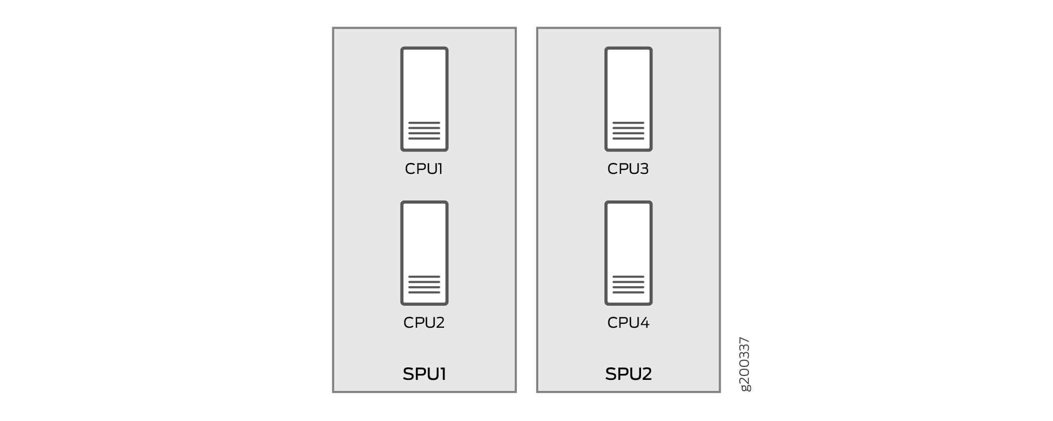
SPC3 flow architecture is same as CP-Lite architecture. The SPC3 physically has two Services Processing Units (SPU) and each SPU has two CPUs.
When you install one or two SPC3s, traffic processing utilizes 75% of the first SPC. When you install three or more SPC3s, the traffic processing utilizes 50% of the first SPC.
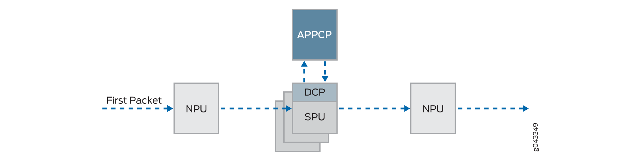
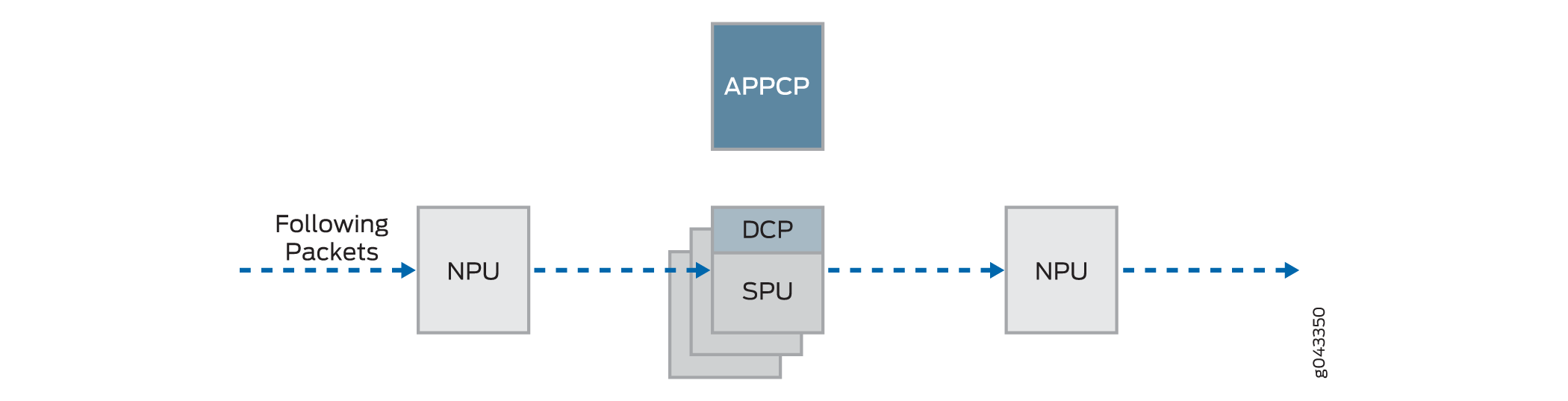
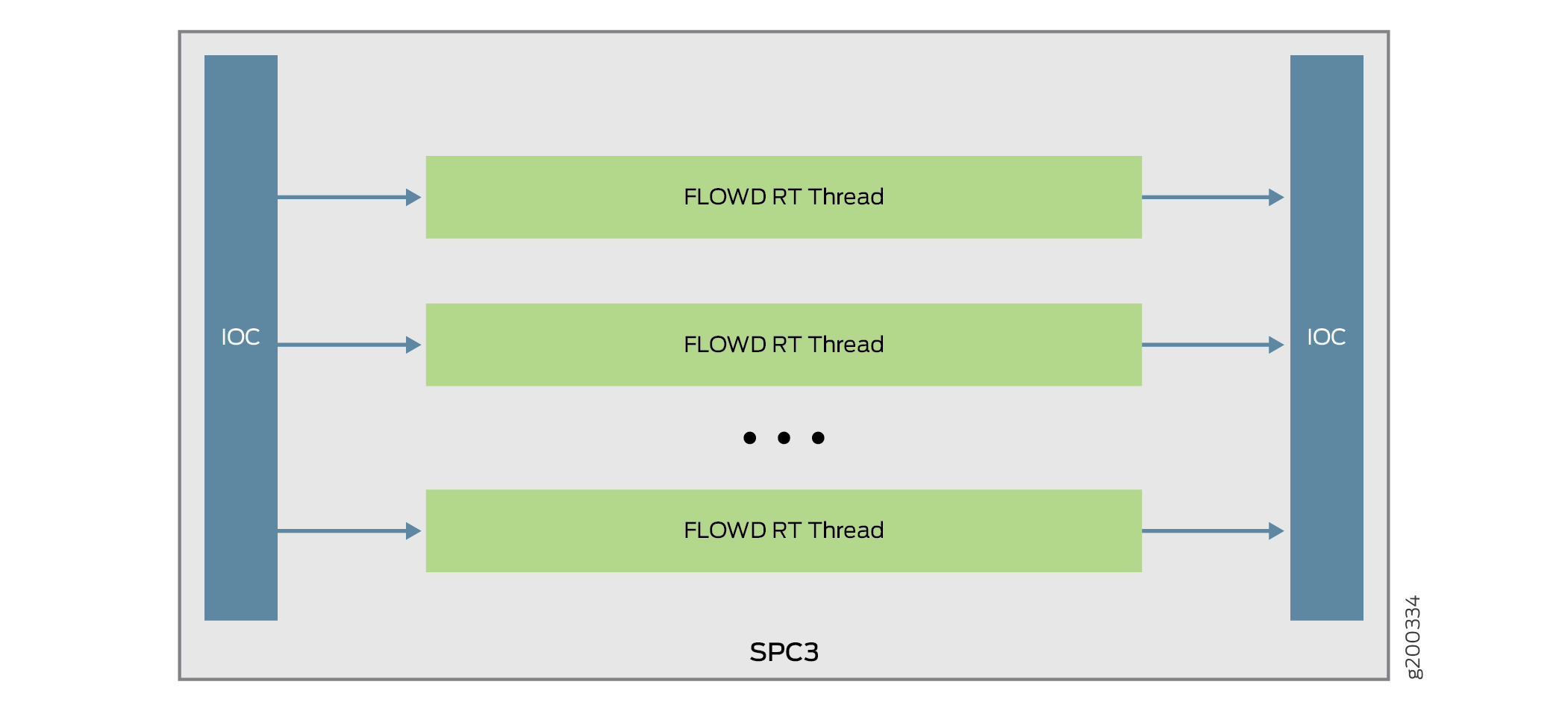
The way the IOC hashes the packets to process the flow is changed. Figure shows the packet flow of SRX Series Firewall with SPC3.
On SPC3, packets are distributed from IOC to each core directly. Since the IOC directly hashes packets to the flowd RT thread, the original LBT thread is removed. The packets are now delivered to the flowd thread instead of SPU. If the security flow installs NP sessions, instead of SPU ID, the session thread ID is used by IOC to forward packets to correct thread associate with the session.
Understanding Load Distribution
All packets that come through a revenue port will be distributed to different SPUs based on hash algorithm, which is same as the existing SRX5000 Line devices hash based on CP-Lite architecture. The hash method varies for different types of traffic. The table below lists hash methods.
|
Protocol |
Ports |
Hash Method |
|
|---|---|---|---|
|
TCP |
L4 src port and dst port |
Hashed by 5-tuple |
|
|
UDP |
Normal |
L4 src port and dst port |
Hashed by 5-tuple |
|
GTP |
L4 src port and dst port |
Hashed by 5-tuple |
|
|
IKE |
L4 src port and dst port |
Hashed by IP pair |
|
|
ICMP |
|
ICMP info is hashed by 5-tuple; ICMP error is hashed by 3-tuple (no ports info) |
|
|
SCTP |
L4 src port and dst port |
Hashed by 5-tuple |
|
|
ESP |
SPI |
Hashed by IP pair |
|
|
AH |
SPI |
Hashed by IP pair |
|
|
GRE |
If PPTP alg is enabled, sport = call id; dport = 0 By default, port is 0x00010001 |
Hashed by 3-tuple |
|
|
PIM |
By default, PIM ports 0x00010001 |
Hashed by 3-tuple |
|
|
FRAGMENT |
First fragment, has the normal ports None first fragment, no ports |
Hashed by 3-tuple |
|
|
Other IP packet |
Ports 0x00010001 |
Hashed by 3-tuple |
|
|
NONE IP |
Not applicable |
Hashed by Mac address and Ethernet Type (Vlan ID) |
|
Understanding NP Session and Service Offload (SOF)
Network processor (NP) session is an IOC-based session that allows and establishes the SPU sessions. The packets that pass the NP session has the following advantages:
-
Avoids session lookup on SPU to gain better performance.
-
Avoids extra packet forwarding between session SPU and hash SPU.
Service offload is a special type of NP session to provide low-latency feature for session that needs basic firewall service. Packets that hits the SOF session on an IOC bypass the packet processing on SPU and is directly forwarded by IOC. The following traffic types support service offload:
-
Basic firewall (without plugin and fragments), IPv4 and IPv6 TCP, UDP traffic
-
IPv4 NAT
-
1Fan-in and 1Fan-out Multicast
-
ALGs such as FTP data session
Understanding J-Flow support on SPC3
J-Flow is the juniper version of industry standard traffic monitoring mechanism. It provides a feature to export snapshot of network traffic statistics to the remote server for network monitoring and further data processing. J-Flow supports v5, v8 and v9 format. All these three versions are supported on SPC3.
Understanding Datapath Debug SPU Support (E2E)
Datapath debug provides filter based end-to-end (E2E) packet debug feature on SRX5000 Line devices. It traces packet path and dump packet content.
On SPC3, JEXEC is the only E2E event type that is supported and the following E2E action types are supported:
-
Count
-
Dump
-
Trace
-
Trace-summary
Understanding Fragmentation Handling, ISSU, and ISHU Support
On SPC3, fragmented packets are forwarded to “fragment core” in a specific PFE based on its header tuple values. After receiving a fragmented packet, flow performs defragmentation and forwards the packet to its session core. The flow logic does not change and remains the same.
While performing the ISSU, the virtual SPUs are synchronized to related virtual SPU IDs. The ISHU support is based on CP-Lite architecture. Basically, two ISHU operations are supported:
-
Insert a new SPC to secondary node.
-
Replace an SPC on secondary node, and the number of SPCs should be same as that of primary node.
Change History Table
Feature support is determined by the platform and release you are using. Use Feature Explorer to determine if a feature is supported on your platform.