Understanding FlowTap and FlowTapLite Architecture
Learn about mediation devices and how they interact with the router running the FlowTap or FlowTapLite application.
The flow-tap architecture consists of one or more mediation devices that send requests to an ACX or MX Series router that supports this feature to monitor incoming data. Any packets that match specific filter criteria are forwarded to a set of one or more content destinations:
-
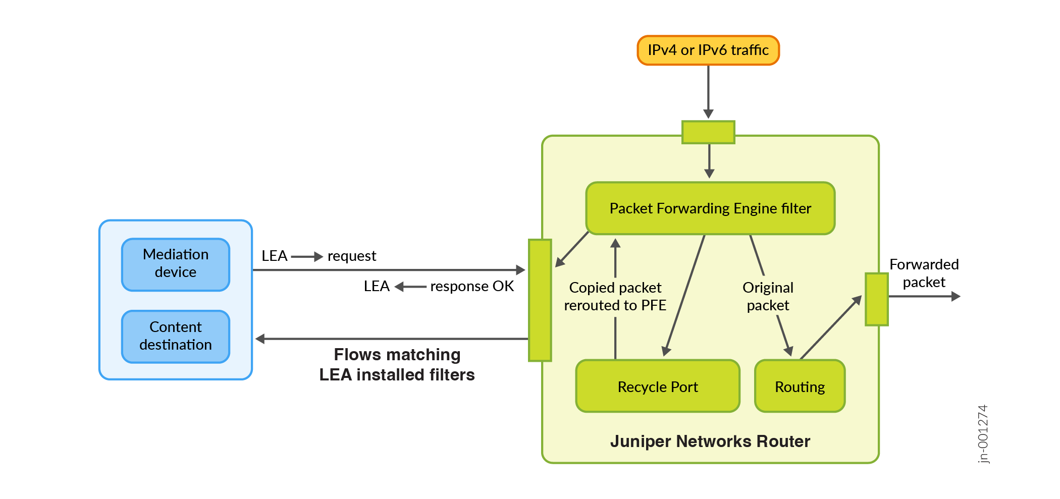
Mediation device—A client that monitors electronic data or voice transfer over the network. The mediation device sends filter requests to the router using DTCP. The clients are not identified for security reasons, but have permissions defined by a set of special login classes.
-
Monitoring platform—A router configured to support the FlowTap or FlowTapLite application. The monitoring platform processes the requests from the mediation devices, applies the dynamic filters, monitors incoming data flows, and sends the matched packets to the appropriate content destinations.
-
Content destination—Recipient of the matched packets from the monitoring platform. Typically the matched packets are sent using an IP Security (IPSec) tunnel from the monitoring platform to another router connected to the content destination. The content destination and the mediation device can be physically located on the same host.
-
Dynamic filters—The Packet Forwarding Engine automatically generates a firewall filter that is applied to all IPv4 routing instances. Each term in the filter includes a
flow-tapaction that is similar to the existingsampleorport-mirroringactions. As long as one of the filter terms matches an incoming packet, the router copies the packet and forwards it to the MPC card or line card that is configured forflow-tapservice. The card runs the packet through the client filters and sends a copy to each matching content destination. For security, filters installed by one client are not visible to others and the CLI configuration does not reveal the identity of the monitored target.Following is a sample filter configuration; note that it is dynamically generated by the router (no user configuration is required):
filter combined_LEA_filter {
    term LEA1_filter {
        from {
            source-address 192.0.2.1;
            destination-address 198.51.100.6;
        }
        then {
            flow-tap;
        }
    }
    term LEA2_filter {
        from {
            source-address 10.1.1.1;
            source-port    23;
        }
        then {
            flow-tap;
        }
    }
}
Figure 1 shows a sample topology that uses two mediation devices and two content destinations.
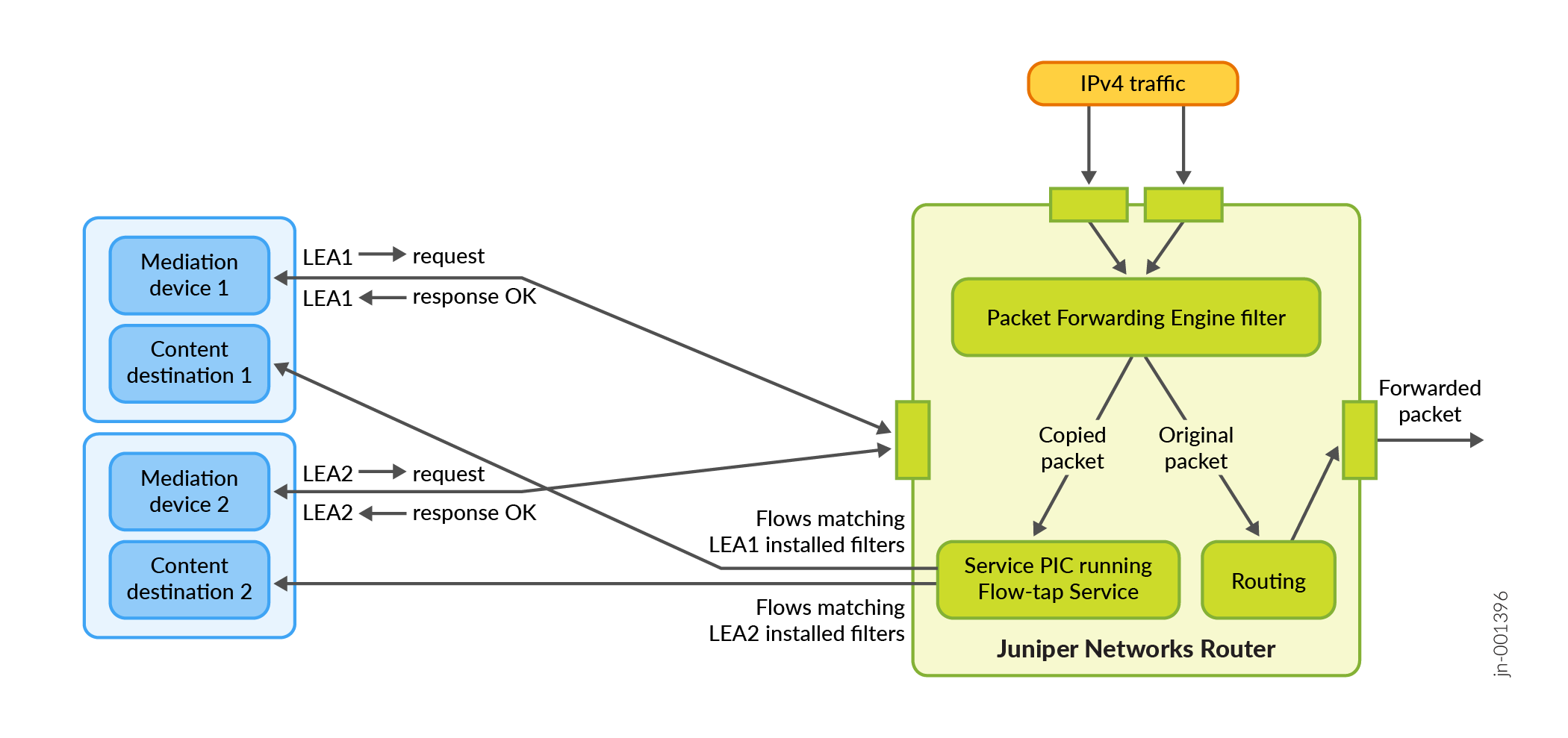
Figure 2 shows a sample topology that uses one mediation device and one content destination. Note that the ACX Series routers use a recycle port.