Easy EVPN LAG (EZ-LAG) Configuration
With the EZ-LAG configuration feature, you can easily configure a small Ethernet virtual private network (EVPN) for a pair of peer provider edge (PE) devices that have attached multihomed or single-homed servers. You use a simplified Junos OS CLI statement hierarchy, and a built-in commit script generates the full configuration.
EVPN fabric PE devices reliably handle traffic to and from attached multihomed end devices by grouping the multihoming links into an EVPN Ethernet segment with an identifier (ESI). You configure the links participating in the Ethernet segment into a link aggregation group (LAG), so we call the set of multihomed links an ESI LAG. In this document, we call the PE devices peer PE devices when they link to multihomed end devices with the same ESI. The PE devices might also have one or more links in a LAG to single-homed end devices, although an EVPN PE device doesn't need to handle single-homed links as an Ethernet segment.
The end devices might be hosts or servers directly attached to the PE devices, or might be customer edge (CE) devices with attached end hosts or servers. For simplicity, in this document we refer to the end devices collectively as servers.
EVPN Multihoming provides redundancy and load balancing between the two switches, and provides a loop-free Layer 2 (L2) network without running STP. However, configuring EVPN multihoming can be complex, and involves configuring many statements correctly across the PE devices in the fabric. With this easy EVPN LAG configuration feature (also called the EZ-LAG feature), we provide a simplified configuration statement hierarchy and a built-in commit script that you can use to set up EVPN multihoming. This feature makes it easy to migrate a multichassis link aggregation group (MC-LAG) topology to a standards-based EVPN-VXLAN multihoming model.
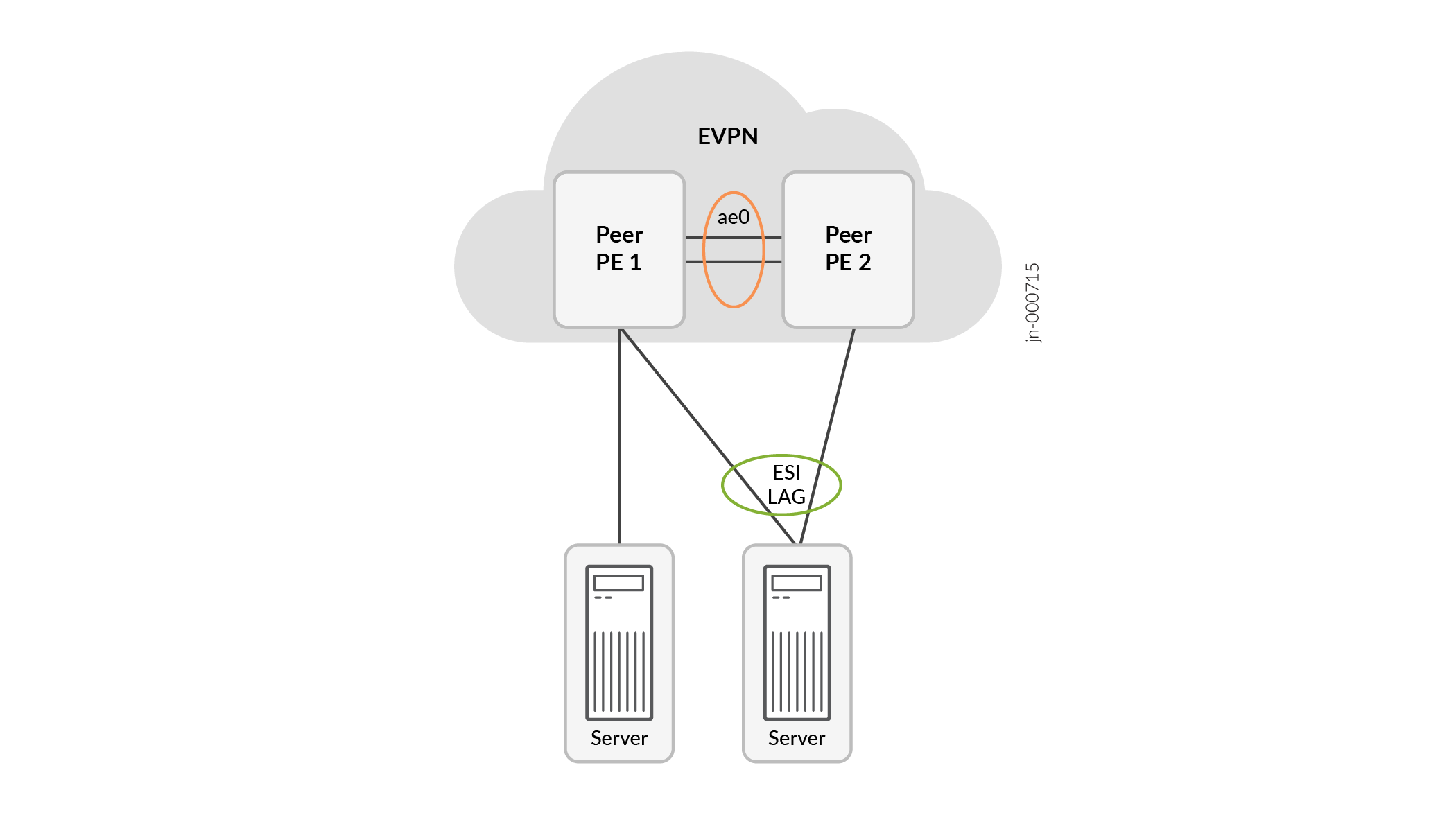
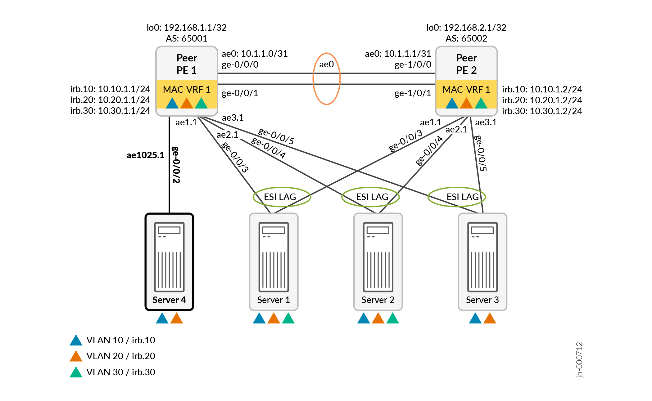
See Figure 1. The supported EVPN topology includes:
-
Two peer PE devices connected back-to-back with an aggregated Ethernet interface bundle
-
An EVPN fabric with VXLAN encapsulation interconnecting the peer PE devices
-
ESI LAG configurations between the peer PE devices and one or more attached multihomed servers
-
Connections between a peer PE device and one or more attached single-homed servers
This feature requires a software license. See the Juniper Licensing User Guide for details on the Juniper Flex Software License model and Juniper Agile Licensing, and the available licenses for the EZ-LAG feature on supported platforms.
Benefits of Using Easy EVPN LAG Configuration
-
Automated configuration: You can easily set up a small EVPN fabric, including ESI-LAGs for multihomed attached servers, without using a network controller. You provide some essential parameters through the CLI, and the device's built-in commit script transforms them into a complete EVPN fabric configuration.
-
Configuration flexibility: You have the flexibility to use the basic and default configuration options, and also customize the generated configuration. You can override many of the commit script default behaviors, and manually configure those elements.
-
Simplified topology migration: You can use this feature to easily migrate a multichassis link aggregation group (MC-LAG) topology to a simple EVPN-VXLAN fabric.
Easy EVPN LAG Configuration Overview
The easy EVPN LAG configuration feature operates at configuration commit time. It consists of:
-
A set of configuration statements at the
[edit services evpn]hierarchy level with which you provide the parameters to set up the prescribed EVPN fabric. -
A built-in commit script that processes the simplified configuration elements at commit time (before the standard Junos OS configuration validity checks) and generates a corresponding EVPN fabric configuration. See Built-in Commit Script for how to enable the EZ-LAG commit script.
You configure a few [edit services evpn] statements to provide the
minimal, required set of parameters to configure the EVPN fabric and the links to
the attached servers.
When you commit the [edit services evpn] configuration statements,
the device invokes the commit script that generates the corresponding EVPN
configuration using the parameters you provided. The commit script derives some
configuration statements specific to the device on which you commit the simplified
configuration. The commit process validates the configuration and generates warning
messages for missing required parameters or misconfigured parameters.
See Commit Script Overview and How Commit Scripts Work for more on commit scripts.
At any time, you can easily include a few more [edit services evpn]
statements to add elements to the existing configuration, such as new VLANs or
connections to new servers.
Overview of the [edit services evpn] Statement Hierarchy
You can specify the minimal set of parameters in just a few configuration statements. For example, consider the following small EVPN-VXLAN fabric with two connected multihomed servers that each host two VLANs:
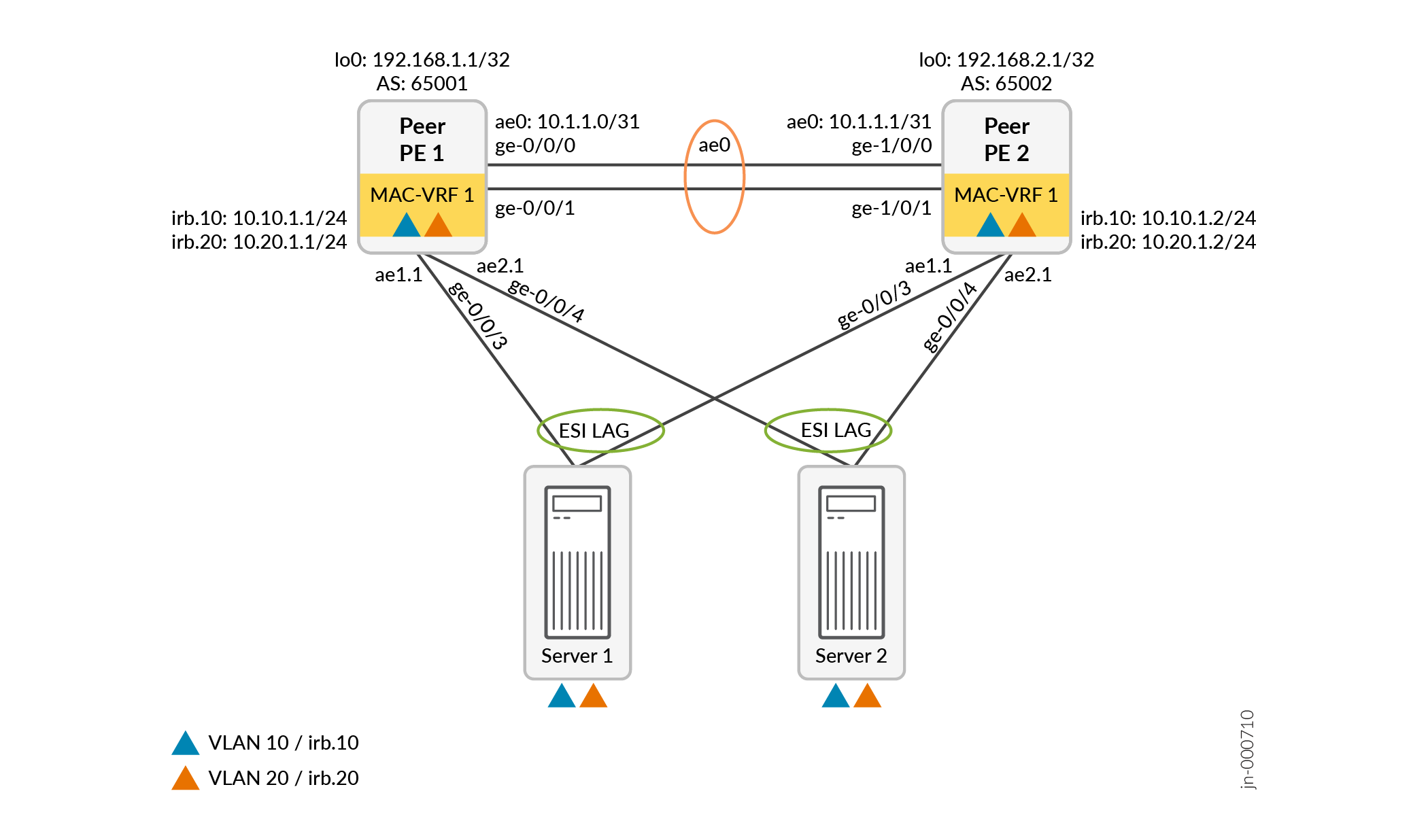
The following few easy EVPN LAG configuration commands provide the minimal required parameters to configure the EVPN fabric from Figure 2 on device Peer PE 1. When you commit these configuration commands, the commit script generates a corresponding full default configuration that might contain 80 to 100 configuration commands:
set services evpn device-attribute peer-id 1 system-id 10:14:15:16:17:10 peer-to-peer peer-subnet inet 10.1.1.0/31 interface-name [ ge-0/0/0 ge-0/0/1 ]
set services evpn device-attribute loopback peer1-subnet 192.168.1.1/32 peer2-subnet 192.168.2.1/32
set services evpn evpn-vxlan irb IRB_10 vlan-id 10 subnet-address inet 10.10.1.1/24
set services evpn evpn-vxlan irb IRB_20 vlan-id 20 subnet-address inet 10.20.1.1/24
set services evpn evpn-vxlan server SERVER_1 esi-lag-id 1 vlan-id-list [ 10 20 ] interface ge-0/0/3
set services evpn evpn-vxlan server SERVER_2 esi-lag-id 2 vlan-id-list [ 10 20 ] interface ge-0/0/4
The [edit services
evpn] command hierarchy has many additional options that give you
flexibility to customize the default generated configuration as needed. The
commit script uses some of the elements you provide in the simplified
configuration to automatically derive other parameters in the generated
configuration. By default, the commit script also generates configuration
commands for other common features in an EVPN fabric, such as loop detection and
storm control on the interfaces from PE devices to servers.
You can include options to:
-
Tell the commit script not to automatically derive some parameters in the generated configuration.
-
Override some of the commit script default values and behaviors.
-
Apply configuration groups to statements the commit script generates.
With any of those options, if the commit script requires any such elements to provide a valid configuration, you must configure those elements manually.
See Simplified CLI Statements and Parameters to Generate the Configuration for details on the parameters each statement and option provide to the commit script, and how those parameters affect the generated configuration.
Built-in Commit Script
The commit script for this feature,
services_evpn_commit_script.py, is enabled by default on
supported platforms.
Because the commit script applies transient configuration changes, for the commit script to work, you must also set the system scripts allow-transients option, as follows:
-
In releases before Junos OS Release 24.2R1, you can set the
allow-transientsoption only at the global level, and the option will apply to any configured commit scripts, as follows:set system scripts commit allow-transients
-
Starting in Junos OS Release 24.2R1, if needed, you can alternatively set the
allow-transientsoption at the individual script level so the option applies only to the EZ-LAG commit script, as follows:set system scripts commit file services_evpn_commit_script.py allow-transients
-
Starting in Junos OS Release 24.4R1, we include the
allow-transientsoption at the EZ-LAG commit script level in the default configuration, so you don't need to explicitly set this option anymore.
Simplified CLI Statements and Parameters to Generate the Configuration
[edit services evpn] hierarchy level. We also show how the commit script maps
the simplified configuration parameters to generate the full configuration.- Default Generated Configuration Overview
- Easy EVPN LAG Configuration Statements and Options
- How the Commit Script Uses Easy EVPN LAG Configuration Elements in the Generated Configuration
Default Generated Configuration Overview
The default generated configuration includes:
-
Underlay and overlay peering using external BGP (EBGP).
-
A default MAC-VRF EVPN instance named __SERVICES_EVPN_EVPN_VXLAN_MAC-VRF_1, with VLAN-aware service type and VXLAN encapsulation, which hosts the VLANs you specify.
You can also configure additional MAC-VRF instances and their member VLANs.
-
IRB interfaces with the specified IPv4 (or IPv6) addresses for routing between VLANs.
By default, the commit script derives a virtual gateway address for each IRB interface as the highest configurable address in the specified IRB subnet address range.
The commit script also assigns a default virtual gateway MAC address of 00:00:5e:00:01:01 if you don't specify that parameter.
-
ESI LAG connections to multihomed servers, and LAG links to single-homed servers.
The commit script assigns aggregated Ethernet interfaces to those links as trunk interfaces with VLAN tagging, flexible Ethernet services encapsulation, and LACP enabled.
-
Lightweight loop detection on the server-facing aggregated Ethernet interfaces associated with the EVPN MAC-VRF instance, with loop detection action
interface
                            down
. See EVPN-VXLAN Lightweight Leaf to Server Loop Detection for more on this feature. -
Storm control on server-facing interfaces.
The commit script generates a default storm control profile named __SERVICES_EVPN_EVPN_VXLAN_STORM_CONTROL, and assigns it to the each server-facing interface. See MAC Filtering, Storm Control, and Port Mirroring Support in an EVPN-VXLAN Environment for more on the storm control feature.
-
Other options commonly included in EVPN network configurations to improve routing table convergence if the aggregated Ethernet interface connections become unstable, such as:
-
no-core-isolationat the[edit (routing-instances name) protocols evpn]hierarchy level . See Understanding When to Disable EVPN-VXLAN Core Isolation. -
no-mac-flush-on-aa-ae-downat the [edit protocols l2-learning platform-parameters]hierarchy level.
-
See an example easy LAG configuration and the corresponding generated configuration here: Easy EVPN LAG Configuration with Multihomed Servers.
The next sections describe the configuration elements in detail.
Easy EVPN LAG Configuration Statements and Options
Table 1 shows the statements and options at the [edit services evpn] configuration statement hierarchy level. The commit
script requires a minimum set of statements to have enough information to
generate a working configuration. The table indicates which statements are
mandatory. You can optionally include other statements to change the commit
script behavior and override default values as needed for your topology and
configuration preferences.
The commit script uses some of the elements you provide in the simplified configuration to automatically derive other parameters in the generated configuration. By default, the commit script also generates configuration statements for supporting common features in an EVPN fabric, such as loop detection and storm control on links to servers.
| Statement and Child Statements | Options | Purpose | Mandatory? |
|---|---|---|---|
|
defaults-override If you configure any of these options, the script will not
automatically derive those parameters from the related
|
|||
|
no-aggregate-device-count-config |
Don't generate the default aggregated Ethernet (aen) interface count configuration statement. |
No |
|
|
no-loop-detect-config |
Don't generate lightweight loop detection configuration statements. |
No |
|
|
no-platform-defaults-config |
Don't generate statements for default platform-specific options. |
No |
|
|
no-policy-and-routing-options-config |
Don't generate default routing and policy options configuration statements. If you specify this option, you must manually provide
configuration for a policy-statement named EXPORT-LO0 at the
Or, you must include the |
No |
|
|
no-storm-control-config |
Don't generate configuration for storm control. |
No |
|
|
no-overlay-bgp-config |
Don't generate BGP configuration for the overlay. |
No |
|
|
no-underlay-config |
Don't generate configuration for the underlay peering. |
No |
|
|
With these statements, you define parameters to configure the
peer PE devices, including the peer interconnection
interfaces, underlay peering, and overlay peering between
them to form the EVPN fabric. The commit script configures
underlay and overlay peering with external BGP (EBGP) by
default. You can optionally specify that the commit script
generate configuration for one of the other available
underlay or overlay protocols. Or, you can alternatively set
the |
|||
|
peer-id peer-id |
Number (1-2) that identifies the PE device (compared to its peer PE device) in the fabric. The commit script uses this value to derive some values that must be unique across the peer PE devices in the generated configuration. |
Yes |
|
|
system-id system-id |
Peer PE device's system ID (MAC address format). The commit script needs this value to derive configuration to set up LACP on ESI LAG interfaces. |
Yes |
|
|
(device-attribute) loopback |
peer1-subnet peer1-subnet peer2-subnet peer2-subnet |
PE device loopback IPv4 subnet addresses for peer PE 1 and peer PE 2 From this parameter, the commit script configures the loopback interface subnet addresses for the peer PE devices, and the router ID for each device. |
Yes |
|
(device-attribute) |
peer-subnet (inet | inet6) subnet-address |
IPv4 or IPv6 subnet address for the interfaces that connect the PE device to its peer PE device. You can specify this option with either the
|
Yes |
|
peer-subnet interface-name [ interface-name … ] |
Name or names of the interfaces that connect the PE device to its peer PE device. |
Yes |
|
|
overlay-connectivity { ibgp } |
Generate a prescribed configuration for overlay peering using internal BGP (IBGP) instead of the default protocol, EBGP. |
No |
|
|
underlay-connectivity { ospf } |
Generate a prescribed configuration for underlay peering using OSPF instead of the default protocol, EBGP. |
No |
|
|
With these statements, you define parameters to configure the peer PE devices to run EVPN with VXLAN encapsulation using one or more VLAN-aware MAC-VRF instances. By default, the commit script enables EVPN-VXLAN in a single
MAC-VRF instance named __SERVICES_EVPN_EVPN_VXLAN_MAC_VRF_1.
If you configure the If needed, you can configure more than one MAC-VRF instance for tenant traffic separation at L2. These statements also provide the parameters to set up the ESI-LAGs to multihomed servers or LAGs to single-homed servers, including the IRB interfaces and the associated VLANs. You can optionally specify to configure DHCP relay for the IRB instances under this stanza as well. |
|||
|
name |
DHCP relay group name. |
No |
|
|
dhcp-server-address dhcp-server-address |
IP address of the DHCP server to enable the DHCP server relay group. |
No |
|
|
relay-source DHCP-relay-source-interface |
IP address of the DHCP relay source loopback interface. The commit script generates DHCP |
No |
|
|
vrf-instance vrf-instance-id |
VRF instance identifier in this configuration for which you want to configure DHCP relay. If you don't specify a vrf-instance-id,
the commit script uses the default VRF instance
( |
No |
|
|
irb-instance |
String to identify an IRB instance and its associated parameters for commit script processing. We recommend choosing IDs that match the parameters of the IRB instance in the generated configuration. For example, use "irb_10" for the IRB instance associated with VLAN 10, which will be irb.10 in the generated configuration. |
Yes |
|
|
apply-config-groups config-groups |
Apply the specified configuration groups to the configuration the commit script generates from the statements at this hierarchy level. |
No |
|
|
no-dhcp-relay |
Exclude this IRB instance from the DHCP relay configuration. This option applies only if you specified to generate
configuration for DHCP relay with the
|
No |
|
|
use-anycast-address |
Configure the IRB instance with an anycast gateway address. With this option, you must include the |
No |
|
|
vlan-id vlan-num |
VLAN ID associated with the IRB instance. The commit script derives the IRB interface name with a matching logical unit number. For example, the commit script configures irb.10 for vlan-num 10. |
Yes |
|
|
(irb irb-instance) instance |
mac-vrf-instance instance-id |
The MAC-VRF instance ID to which the IRB instance belongs. The commit script generates MAC-VRF instance configuration statements using MAC-VRF instance name __SERVICES_EVPN_EVPN_VXLAN_MAC_VRF_instance-id. |
No* *If you don't configure this option, the commit script creates a MAC-VRF instance using default instance-id 1. |
|
vrf-instance instance-id |
The Layer 3 (L3) virtual routing and forwarding (VRF) instance to which this IRB instance belongs. If you specify this option, the commit script generates VRF instance configuration statements for VRF instance name __SERVICES_EVPN_EVPN_VXLAN_VRF_instance-id. |
No* *If you don't configure this option, the commit script uses
the default VRF instance (which corresponds to the
|
|
|
(irb irb-instance) |
inet (ipv4-subnet-address | [ipv4-addr1 ipv4-addr 2 …]) |
IPv4 subnet address or list of subnet addresses for the IRB interface. For simplicity, you can configure the same IRB subnet address on both peer PE devices. By default, the commit script uses the PE peer ID to derive different IRB subnet addresses for each peer device based on the configured ipv4-subnet-address value. Alternatively, you can set the subnet addresses you
want on each peer PE device, and include the
router-advertisement configuration
statements the commit script generates for the IRB interfaces. |
Yes* *You must configure at least one subnet address for the IRB
instance using either the |
|
inet6 (ipv6-subnet-address | [ipv6-addr1 ipv6-addr 2 …]) |
IPv6 subnet address for the IRB interface. The commit script has the same default behavior with this
option as with the |
Yes* *You must configure at least one subnet address for the IRB
instance using either the |
|
|
no-irb-address-auto-derive |
Don't derive IRB subnet addresses in the generated configuration for this IRB instance. You must specify this option if you don't want the commit
script default behavior that uses the PE peer ID to derive
different IRB subnet addresses for each peer device from the
same configured ( With this option, the commit script uses the exact
This option is also available at the |
No |
|
|
virtual-gateway-v4-address virtual-gateway-v4-address |
Virtual gateway IPv4 address for the IRB interface. If you don't include this option, by default the commit
script derives a virtual gateway IPv4 address from the
|
No |
|
|
virtual-gateway-v6-address virtual-gateway-v6-address |
Virtual gateway IPv6 address for the IRB interface. If you don't include this option, the commit script has the
same default behavior to derive the
|
No |
|
|
name |
A unique name to identify a server connected to the peer PE device, such as SERVER_1 or HostA. This value is used internally to associate server-related parameters with the statements to generate for that server. You might see this server name in description parameters for related statements in the generated configuration. |
Yes |
|
|
apply-config-groups config-groups |
Apply the specified configuration groups to the configuration the commit script generates from the statements at this hierarchy level. |
No |
|
|
enable-pxe-boot |
Enable this connected server to use a preboot execution environment (PXE) boot process. The commit script configures LACP |
No |
|
|
esi-lag-id esi-lag-id |
ESI LAG connection ID for this server. The commit script assigns an aggregated Ethernet interface for the connection to this server by adding esi-lag-id to the base interface name ae0 (so for example, esi-lag-id 1 uses ae1). |
Yes* *You must specify at least one |
|
|
single-home-id single-home-id |
Single-homed connection ID for the named server. The commit script assigns an aggregated Ethernet interface for the connection to this server by adding single-home-id to the base interface name ae1024 (so for example, single-home-id 1 uses ae1025). |
Yes* *You must specify at least one
esi-lag-id option in the previous
row.) |
|
|
interface (interface-name | [ interface-name …]) |
Interface name or list of interface names for the physical links from the peer PE device to this server. |
Yes |
|
|
vlan-id-list [vlan-id-list] |
List of VLAN IDs hosted by this MAC-VRF instance and server. |
Yes* *You must configure at least one VLAN ID list (with at least
one VLAN ID in it) for each server, either at this
|
|
|
(server name) mac-vrf-instance |
instance-id |
Identifier for a MAC-VRF instance that hosts this server. If you don't specify this option, the commit script generates configuration that associates these server parameters with the default MAC-VRF instance (named __SERVICES_EVPN_EVPN_VXLAN_MAC_VRF_1). |
No |
|
vlan-id-list [vlan-id-list] |
List of VLAN IDs hosted by this MAC-VRF instance and server. |
Yes* *You must configure at least one VLAN ID list (with at least
one VLAN ID in it) for each server, either at this MAC-VRF
instance level or at the |
|
|
With these statements, you specify parameters for configuration elements that are common across the peer PE devices in the EVPN fabric, such as the default VLAN and anycast gateway addresses. The commit script has default values it uses if you don't configure these options. |
|||
|
anycast-mac anycast-mac |
Globally use the specified anycast virtual gateway MAC address in the generated configuration. |
No |
|
|
default-vlan vlan-id |
Use this VLAN ID (1-4094) as the default VLAN in the generated configuration. The commit script uses the system default VLAN ID if you don't configure this. |
No |
|
|
no-irb-address-auto-derive |
Don't derive IRB interface subnet addresses in the generated
configuration for all IRB instances. Instead, use the exact
IPv4 or IPv6 subnet addresses you specify with the
Otherwise, by default, the commit script derives the IRB
subnet address from the You can alternatively set this option at the |
No |
|
|
start-aggregate-ethernet-index num |
Use this number as the starting index in aggregated Ethernet interface names for ESI LAG links to attached servers. The commit script starts at ae1 by default for ESI LAG links to servers, and reserves ae0 interface names only for the links between the peer PEs. Note:
This option does not affect generated interface names for links to single-homed servers. The commit script uses aggregated Ethernet interface names starting at ae1025 for single-homed server links. |
No |
|
| virtual-gateway-mac virtual-gateway-mac |
Use this virtual gateway MAC address for both IPv4 and IPv6 traffic in the generated configuration. Specify the |
No |
|
|
(global-parameters) mtu |
overlay overlay-mtu |
Specify the maximum transmission unit (MTU) in bytes to set in the generated configuration for the interfaces used in the overlay peering, instead of the default MTU value. The default MTU value varies by platform and type of interface (or protocol) for which you configure the value. |
No |
|
underlay underlay-mtu |
Specify the MTU in bytes to set in the generated configuration for the interfaces used in the overlay peering, instead of the default MTU value. The default MTU value varies by platform and type of interface (or protocol) for which you configure the value. |
No |
|
|
(global-parameters) virtual-gateway |
v4-mac v4-mac |
Globally use this virtual gateway MAC address for IPv4 traffic in the generated configuration. The commit script uses 00:00:5e:00:01:01 by default if you
don't configure this option or the
|
No |
|
v6-mac v6-mac |
Globally use this virtual gateway MAC address for IPv6 traffic in the generated configuration. The commit script uses 00:00:5e:00:02:01 by default if you
don't configure this option or the
|
No |
|
How the Commit Script Uses Easy EVPN LAG Configuration Elements in the Generated Configuration
Table 2 lists configuration elements and default values that the commit script uses or derives from the simplified configuration you provide.
| Configuration Element | Default or Derived Value |
|---|---|
|
General or Shared Elements |
|
|
Number of aggregated Ethernet interface connected device for
|
num is 255 by default. (Some platforms might use a different default platform-specific value.) |
|
Peer PE identifier, to associate specified or derived parameters with the corresponding peer PE device From |
Parameter peer-id is required for each peer PE device (there is no default value). The peer-id can have value 1 or 2. |
|
Peer PE device loopback interface (lo0) address From
|
Use the loopback interface address on peer PE device peer-id from the provided loopback subnet addess for that peer ID. |
|
Router ID, for From
|
Assigned the same value as the device's loopback interface address. |
|
Load balancing routing options policy for per-flow load balancing |
set policy-options policy-statement pplb then load-balance per-packet set routing-options forwarding-table export pplb |
|
Storm control configuration for each server-facing interface |
Storm control configuration is platform-dependent. See Platform-Specific Behavior for EZ-LAG Generated Configurations for the differences in the generated configuration per platform. |
|
Peer to Peer PE Device Connections You specify a peer PE device ID used internally to track the parameters that apply to that configured EVPN peer PE device as follows:
|
|
|
Aggregated Ethernet interface name |
ae0 |
|
Aggregated Ethernet interface address From
|
For configuration simplicity, you configure the same subnet-address on both peer PE devices. The commit script derives the interface address based on peer-id as follows:
For example, if the IPv4 subnet-address is 10.0.1.0/31:
|
|
Aggregated Ethernet interface member physical interface or interfaces From |
Parameter [ interface-name ... ] is required; set those interfaces as member links in ae0. |
|
Peer PE Device to Server Connections You specify server names and assign IDs that represent the links to those servers (either multihomed ESI LAG connections or single-homed connections), as follows:
The commit script uses the server names internally to associate configured elements with an attached server, but also displays these names in the description element of related generated configuration statements. |
|
| Starting index for assigning aggregated Ethernet interface names for ESI LAG links to multihomed servers |
Default is 1 (ae1) To override the default value and assign a different starting index (num), configure:
This option affects only the starting index for aggregated
Ethernet interfaces to multihomed servers
( This option doesn't affect how the commit script allocates
single-homed server links ( |
|
Name of physical interface or interfaces from peer PE device to server (single interface or list of interfaces) From |
Required parameter per server, no default |
|
Aggregated Ethernet interface name (aeindex) and logical unit (unit num) From
|
Derive as follows based on server link ID and configured
MAC-VRF instance ID (or default MAC-VRF
instance-id 1):
|
|
Aggregated Ethernet interface options and member VLANs From
|
Enable VLAN tagging, flexible Ethernet services encapsulation, and trunk interface mode. Set member VLANs from configured server
For example, for esi-lag-id 1 (interface
name ae1) in the default
MAC-VRFinstance-id 1 with
set interfaces ae1 vlan-tagging set interfaces ae1 encapsulation flexible-ethernet-services set interfaces ae1 unit 1 family ethernet-switching interface-mode trunk set interfaces ae1 unit 1 family ethernet-switching vlan members 10 set interfaces ae1 unit 1 family ethernet-switching vlan members 20 |
|
System ID for LACP on PE device to server links (MAC address format) From:
|
Derive from system-id per server link by adding the server link ID as follows: system-id + esi-lag-id OR system-id + single-home-id For example, if system-id is 10:11:12:13:14:15, then for esi-lag-id 1 (ae1), LACP system ID is 10:11:12:13:14:16 in the generated LACP configuration for that link: set interfaces ae1 aggregated-ether-options lacp active set interfaces ae1 aggregated-ether-options lacp system-id 10:11:12:13:14:16 Note:
To skip configuring LACP for a peer-server link, include the following option: set services evpn evpn-vxlan server server-name no-lacp |
|
Multihomed server interface ESI LAG configuration From |
Automatically derive the ESI: set interfaces aeesi-lag-id esi auto-derive type-1-lacp set interfaces aeesi-lag-id all-active |
|
Lightweight loop detection configuration on server-facing logical aggregated Ethernet interfaces From
|
Generates set protocols loop-detect enhanced interface aeesi-lag-id.instance-id vlan-id vlan-id set protocols loop-detect enhanced interface aeesi-lag-id.instance-id loop-detect-action interface-down set protocols loop-detect enhanced interface aeesi-lag-id.instance-id transmit-interval 1s set protocols loop-detect enhanced interface aeesi-lag-id.instance-id revert-interval 60 For more on this loop detection feature, see EVPN-VXLAN Lightweight Leaf to Server Loop Detection. Note: The commit script generates the loop
detection configuration only on platforms that support the
EVPN-VXLAN lightweight loop detection feature (see Feature
Explorer).
|
|
EVPN, VXLAN, and IRB Interface Elements Supported EVPN instance parameters in generated configuration: MAC-VRF instance type, VLAN-aware service type, and VXLAN encapsulation |
|
|
MAC-VRF EVPN instance name From: |
If you don't configure one or more
Otherwise, for each configured instance-id, the MAC-VRF instance name is __SERVICES_EVPN_EVPN_VXLAN_MAC_VRF_instance-id. |
|
Aggregated Ethernet interface logical unit per MAC-VRF instance From
|
Derive and configure associated logical interface as
follows: set routing-instances __SERVICES_EVPN_EVPN_VXLAN_MAC_VRF_instance-id interface ae(esi-lag-id | single-home-id).instance-id |
|
Route distinguisher (RD) for EVPN instance From :
|
Route distinguisher for each MAC-VRF routing instance is derived from the peer PE device loopback subnet address and the MAC-VRF instance-id as follows: peer<peer-id>-subnet:instance-id |
|
Target extended community for EVPN instance From |
vrf-target:1:instance-id |
|
VLANs (bridge domains) hosted in the EVPN instance From: |
VLAN names are SERVICES_EVPN_EVPN_VXLAN_VLAN_vlan-id |
|
IRB interface logical units corresponding to configured server VLANs From: |
IRB interface logical unit is vlan-id in generated configuration for:
|
|
IRB interface address (to configure From If you want the generated configuration to have different IRB interface subnet-address values that you explicitly set per peer PE device (instead of the default addresses derived from a common configured subnet-address value), then configure the following option:
|
Derive different addresses per peer PE device from IPv4 or IPv6 subnet-address. Parameter subnet-address is required, and for configuration simplicity, you configure the same subnet-address on both peer PE devices. The commit script derives different IRB interface addresses per peer PE device based on subnet-address and peer-id, as follows:
For example, if IPv4 subnet-address is 10.10.1.0/24:
Note:
The commit process doesn't do a commit check to enforce setting the same subnet address across both devices. By default, the commit script will derive the IRB interface subnet address based on the configured subnet-address at this hierarchy level. As a result, we strongly recommend you use the same
subnet address for this parameter on both peer PE
devices, and only set the |
|
IRB interface virtual gateway address From Include the following options at
|
Derive the virtual gateway address for the IRB instance as the highest configurable address in the IPv4 or IPv6 subnet-address subnet range. For example, if the IPv4 ( Similarly, for example, if the IPv6 ( |
|
IRB interface virtual gateway MAC address Include the following options at
|
IPv4 virtual gateway MAC address: 00:00:5e:00:01:01 IPv6 virtual gateway MAC address: 00:00:5e:00:02:01 |
|
VXLAN network identifier (VNI) mapping From: |
Add vlan-id to a base value of 10000 |
|
Underlay Peering for PE Devices—Default Protocol: EBGP BGP group name: __SERVICES_EVPN_EVPN_VXLAN_EBGP_UNDERLAY |
|
|
Autonomous system (AS) number |
65000 + peer-id |
|
Local AS number and peer AS number for BGP group
configuration ( From |
On The AS numbers are reversed on the other peer PE device
|
|
Local device address and peer neighbor address for BGP group
configuration ( From |
On peer PE device The local address and neighbor address are reversed on the
other peer PE device |
|
MTU size for underlay or overlay peering interfaces |
Use the See Media MTU and Protocol MTU for more on MTU settings. |
|
Routing policy to advertise loopback interface to EBGP peer PE device |
set policy-options policy-statement EXPORT-LO0 term LOOPBACK from interface lo0.0 set policy-options policy-statement EXPORT-LO0 term LOOPBACK then accept set policy-options policy-statement EXPORT-LO0 term REJECT then reject set protocols bgp group __SERVICES_EVPN_EVPN_VXLAN_EBGP_UNDERLAY export EXPORT-LO |
|
Overlay Peering for PE Devices—Default Protocol: EBGP BGP group name: __SERVICES_EVPN_EVPN_VXLAN_EBGP_OVERLAY |
|
|
Autonomous system (AS) number (for From |
65000 + peer-id |
|
Local device address and peer neighbor address for generated
BGP group configuration ( From
|
Each peer device uses the provided |
|
Other Underlay Peering Options for PE Devices—OSPF If you configure |
|
|
Aggregated Ethernet interface logical unit with OSPF underlay peering |
ae0.0 |
|
OSPF area |
0.0.0.0 |
|
Other Overlay Peering Options for PE Devices—IBGP If you configure |
|
|
Autonomous system number for internal BGP peering
( |
65000 |
|
Local device address and peer neighbor address for generated
IBGP group configuration ( From
|
Same as with an EBGP overlay—each peer device uses the
provided |
|
Option to Configure DHCP Relay for a VRF Routing Instance If you configure |
|
|
DHCP Relay group configuration From
|
Derived DHCP relay group name is SERVICES_EVPN_EVPN_VXLAN_VRFname and default configuration is: [edit routing-instances __SERVICES_EVPN_EVPN_VXLAN_VRF_instance-id forwarding-options] set dhcp-relay forward-only set dhcp-relay server-group SERVICES_EVPN_EVPN_VXLAN_VRFnamedhcp-server-address [edit routing-instances __SERVICES_EVPN_EVPN_VXLAN_VRF_instance-id forwarding-options dhcp-relay group SERVICES_EVPN_EVPN_VXLAN_VRFname] set active-server-group SERVICES_EVPN_EVPN_VXLAN_VRFname set overrides relay-source relay-source-interface set relay-option-82 server-id-override |
Platform-Specific Behavior for EZ-LAG Generated Configurations
See the Simplified configuration for ESI LAGS with EVPN dual homing (EZ-LAG) entry in Feature Explorer to review the platforms and releases in which we support the EZ-LAG feature.
Use the following table to review platform-specific differences in the generated configuration on different platforms that support the EZ-LAG feature:
|
Platform |
Difference |
|---|---|
|
EX9204, EX9208, and EX9214 routers |
Storm control default generated configuration: set forwarding-options storm-control-profiles __SERVICES_EVPN_EVPN_VXLAN_STORM_CONTROL all bandwidth-percentage 1 set interfaces interface-name family ethernet-switching storm-control __SERVICES_EVPN_EVPN_VXLAN_STORM_CONTROL |
|
Other supported platforms besides EX9204, EX9208, and EX9214 routers |
Storm control default generated configuration: set forwarding-options storm-control-profiles __SERVICES_EVPN_EVPN_VXLAN_STORM_CONTROL all bandwidth-percentage 1 set interfaces interface-name ether-options ethernet-switch-profile storm-control __SERVICES_EVPN_EVPN_VXLAN_STORM_CONTROL |
Easy EVPN LAG Configuration with Multihomed Servers
Figure 3 shows a topology with two multihomed servers connected to two peer PE devices. The peer PE devices are connected back-to-back in a small EVPN fabric that hosts two server VLANs (VLAN IDs 10 and 20).
- Simplified Configuration with Two Multihomed Servers
- Generated Configuration with Two Multihomed Servers
- Derived Values in Generated Configuration
Simplified Configuration with Two Multihomed Servers
This section shows an example of a minimal easy EVPN LAG configuration for the
topology in Figure 3. You use statements in the [edit services evpn] configuration stanza. This configuration provides all
of the required parameters for the commit script to generate a corresponding
EVPN-VXLAN configuration. You configure only a few elements that are specific to
each peer PE device. Otherwise, most of the configuration is the same on both
devices.
In this example, both peer PE devices host the same VLANs and use the same physical interface names to link to the multihomed servers, so those required configuration parameters can all be part of the common configuration across the peer PE devices. However, because physical interface allocations per device are usually different in actual customer deployments, we include the easy EVPN LAG configuration statements for those parameters separately below for each peer PE device.
The commit script uses default values for some elements. It also automatically derives other values for the generated configuration from the parameters in the simplified configuration, as mentioned earlier.
In this configuration, note that we configure the following common subnet address parameters across both peer PE devices. We do this because the commit script uses or automatically derives values on each peer PE device based on the peer-id on which the script is running:
-
The device loopback subnet addresses for each device:
set services evpn device-attribute loopback peer1-subnet peer1-subnet peer2-subnet peer2-subnet
The commit script uses the provided loopback subnet address as the local address for the peer-id on which it runs. It uses the other peer-id loopback subnet address as its peer PE device neighbor address.
-
The peer PE device peer-to-peer link subnet addresses:
set services evpn device-attribute peer-to-peer peer-subnet inet subnet-address
The commit script uses the aggregated Ethernet interface subnet address for peer-id 1 as the configured subnet-address, and derives the address for peer-id 2 as that subnet-address plus 1 in the low-order byte of the address subnet range.
-
The IRB interface subnet address for each IRB interface that serves each VLAN:
set services evpn evpn-vxlan irb irb-instance subnet-address inet subnet-address
The commit script derives an IRB interface address in the same way as for the peer-to-peer aggregated Ethernet addresses above—it uses the configured subnet-address for peer-id 1, and adds 1 to the low-order byte of that subnet-address address range for peer-id 2.
The commit process doesn't do a commit check to enforce setting the same
subnet address across both devices. By default, the commit script will
automatically derive these addresses based on the provided
subnet-address
peer-id 1 values. As a result, we strongly recommend that
you make sure to set these subnet addresses to the same base value on both
peer PE devices in an easy EVPN LAG configuration. That way the default
address derivation works as expected for the loopback device, loopback peer
link, and IRB interface subnet addresses on each peer PE device.
See Derived Values in Generated Configuration for details on all of the values that the commit script derives for the generated configuration.
- Easy EVPN LAG Configuration for Two Multihomed Servers
- Default Parameters Not Specified in the Simplified Configuration
Easy EVPN LAG Configuration for Two Multihomed Servers
Peer PE 1:
set services evpn device-attribute peer-id 1 set services evpn device-attribute peer-to-peer peer-subnet interface-name ge-0/0/0 set services evpn device-attribute peer-to-peer peer-subnet interface-name ge-0/0/1 set services evpn evpn-vxlan server SERVER_1 interface ge-0/0/3 set services evpn evpn-vxlan server SERVER_2 interface ge-0/0/4
Peer PE 2:
set services evpn device-attribute peer-id 2 set services evpn device-attribute peer-to-peer peer-subnet interface-name ge-1/0/0 set services evpn device-attribute peer-to-peer peer-subnet interface-name ge-1/0/1 set services evpn evpn-vxlan server SERVER_1 interface ge-0/0/3 set services evpn evpn-vxlan server SERVER_2 interface ge-0/0/4
Common Configuration on Both Peer PE Devices:
set services evpn device-attribute loopback peer1-subnet 192.168.1.1/32 peer2-subnet 192.168.2.1/32 set services evpn device-attribute system-id 10:11:12:13:14:10 set services evpn device-attribute peer-to-peer peer-subnet inet 10.1.1.0/31 set services evpn evpn-vxlan irb irb_10 vlan-id 10 set services evpn evpn-vxlan irb irb_10 subnet-address inet 10.10.1.1/24 set services evpn evpn-vxlan irb irb_20 vlan-id 20 set services evpn evpn-vxlan irb irb_20 subnet-address inet 10.20.1.1/24 set services evpn evpn-vxlan server SERVER_1 esi-lag-id 1 set services evpn evpn-vxlan server SERVER_1 vlan-id-list [ 10 20 ] set services evpn evpn-vxlan server SERVER_2 esi-lag-id 2 set services evpn evpn-vxlan server SERVER_2 vlan-id-list [ 10 20 ]
Default Parameters Not Specified in the Simplified Configuration
The commit script uses the following default elements that you don't specify in this simplified configuration:
| Configuration Element | Default Value |
|---|---|
|
Aggregated Ethernet device count |
255 |
|
Peer to peer PE device links |
ae0 |
|
Overlay peering autonomous system number base value |
65000 |
|
Underlay and overly peering protocol |
EBGP |
|
Underlay BGP group name |
__SERVICES_EVPN_EVPN_VXLAN_EBGP_UNDERLAY |
|
Underlay export policy name and policy statement |
EXPORT-LO0 |
|
Overlay BGP group name |
__SERVICES_EVPN_EVPN_VXLAN_EBGP_OVERLAY |
|
EVPN-VXLAN MAC-VRF instance |
instance-id 1 Name: __SERVICES_EVPN_EVPN_VXLAN_MAC_VRF_1
|
|
Virtual gateway MAC address (for IPv4) |
00:00:5e:00:01:01 |
|
VLAN name |
SERVICES_EVPN_EVPN_VXLAN_VLAN_vlan-id |
|
Storm control profile name |
__SERVICES_EVPN_EVPN_VXLAN_STORM_CONTROL |
Generated Configuration with Two Multihomed Servers
With the easy EVPN LAG configuration commit script enabled, when you commit the configuration in Simplified Configuration with Two Multihomed Servers, the commit script generates the following EVPN-VXLAN configuration. By default, the commit script configures storm control and lightweight loop detection on the server-facing interfaces.
See Derived Values in Generated Configuration for all the values the commit script derives in this generated configuration from the simplified configuration.
Peer PE 1:
set chassis aggregated-devices ethernet device-count 255 set chassis network-services enhanced-ip set interfaces ge-0/0/0 ether-options 802.3ad ae0 set interfaces ge-0/0/1 ether-options 802.3ad ae0 set interfaces ge-0/0/3 ether-options ethernet-switch-profile storm-control __SERVICES_EVPN_EVPN_VXLAN_STORM_CONTROL set interfaces ge-0/0/3 ether-options 802.3ad ae1 set interfaces ge-0/0/4 ether-options ethernet-switch-profile storm-control __SERVICES_EVPN_EVPN_VXLAN_STORM_CONTROL set interfaces ge-0/0/4 ether-options 802.3ad ae2 set interfaces ae0 aggregated-ether-options lacp active set interfaces ae0 unit 0 family inet address 10.1.1.0/31 set interfaces ae1 vlan-tagging set interfaces ae1 encapsulation flexible-ethernet-services set interfaces ae1 esi auto-derive type-1-lacp set interfaces ae1 esi all-active set interfaces ae1 aggregated-ether-options lacp active set interfaces ae1 aggregated-ether-options lacp system-id 10:11:12:13:14:11 set interfaces ae1 unit 1 family ethernet-switching interface-mode trunk set interfaces ae1 unit 1 family ethernet-switching vlan members 10 set interfaces ae1 unit 1 family ethernet-switching vlan members 20 set interfaces ae2 vlan-tagging set interfaces ae2 encapsulation flexible-ethernet-services set interfaces ae2 esi auto-derive type-1-lacp set interfaces ae2 esi all-active set interfaces ae2 aggregated-ether-options lacp active set interfaces ae2 aggregated-ether-options lacp system-id 10:11:12:13:14:12 set interfaces ae2 unit 1 family ethernet-switching interface-mode trunk set interfaces ae2 unit 1 family ethernet-switching vlan members 10 set interfaces ae2 unit 1 family ethernet-switching vlan members 20 set interfaces irb unit 10 virtual-gateway-accept-data set interfaces irb unit 10 family inet address 10.10.1.1/24 virtual-gateway-address 10.10.1.254 set interfaces irb unit 10 virtual-gateway-v4-mac 00:00:5e:00:01:01 set interfaces irb unit 20 virtual-gateway-accept-data set interfaces irb unit 20 family inet address 10.20.1.1/24 virtual-gateway-address 10.20.1.254 set interfaces irb unit 20 virtual-gateway-v4-mac 00:00:5e:00:01:01 set interfaces lo0 unit 0 family inet address 192.168.1.1/32 primary set interfaces lo0 unit 0 family inet address 192.168.1.1/32 preferred set forwarding-options storm-control-profiles __SERVICES_EVPN_EVPN_VXLAN_STORM_CONTROL all bandwidth-percentage 1 set policy-options policy-statement EXPORT-LO0 term LOOPBACK from interface lo0.0 set policy-options policy-statement EXPORT-LO0 term LOOPBACK then accept set policy-options policy-statement EXPORT-LO0 term REJECT then reject set policy-options policy-statement pplb then load-balance per-packet set routing-instances __SERVICES_EVPN_EVPN_VXLAN_MAC_VRF_1 instance-type mac-vrf set routing-instances __SERVICES_EVPN_EVPN_VXLAN_MAC_VRF_1 protocols evpn encapsulation vxlan set routing-instances __SERVICES_EVPN_EVPN_VXLAN_MAC_VRF_1 protocols evpn default-gateway no-gateway-community set routing-instances __SERVICES_EVPN_EVPN_VXLAN_MAC_VRF_1 vtep-source-interface lo0.0 set routing-instances __SERVICES_EVPN_EVPN_VXLAN_MAC_VRF_1 service-type vlan-aware set routing-instances __SERVICES_EVPN_EVPN_VXLAN_MAC_VRF_1 interface ae1.1 set routing-instances __SERVICES_EVPN_EVPN_VXLAN_MAC_VRF_1 interface ae2.1 set routing-instances __SERVICES_EVPN_EVPN_VXLAN_MAC_VRF_1 route-distinguisher 192.168.1.1:1 set routing-instances __SERVICES_EVPN_EVPN_VXLAN_MAC_VRF_1 vrf-target target:1:1 set routing-instances __SERVICES_EVPN_EVPN_VXLAN_MAC_VRF_1 vlans SERVICES_EVPN_EVPN_VXLAN_VLAN_10 vlan-id 10 set routing-instances __SERVICES_EVPN_EVPN_VXLAN_MAC_VRF_1 vlans SERVICES_EVPN_EVPN_VXLAN_VLAN_10 l3-interface irb.10 set routing-instances __SERVICES_EVPN_EVPN_VXLAN_MAC_VRF_1 vlans SERVICES_EVPN_EVPN_VXLAN_VLAN_10 vxlan vni 10010 set routing-instances __SERVICES_EVPN_EVPN_VXLAN_MAC_VRF_1 vlans SERVICES_EVPN_EVPN_VXLAN_VLAN_20 vlan-id 20 set routing-instances __SERVICES_EVPN_EVPN_VXLAN_MAC_VRF_1 vlans SERVICES_EVPN_EVPN_VXLAN_VLAN_20 l3-interface irb.20 set routing-instances __SERVICES_EVPN_EVPN_VXLAN_MAC_VRF_1 vlans SERVICES_EVPN_EVPN_VXLAN_VLAN_20 vxlan vni 10020 set routing-options router-id 192.168.1.1 set routing-options autonomous-system 65001 set routing-options forwarding-table export pplb set protocols bgp group __SERVICES_EVPN_EVPN_VXLAN_EBGP_UNDERLAY type external set protocols bgp group __SERVICES_EVPN_EVPN_VXLAN_EBGP_UNDERLAY local-address 10.1.1.0 set protocols bgp group __SERVICES_EVPN_EVPN_VXLAN_EBGP_UNDERLAY export EXPORT-LO0 set protocols bgp group __SERVICES_EVPN_EVPN_VXLAN_EBGP_UNDERLAY local-as 65004 set protocols bgp group __SERVICES_EVPN_EVPN_VXLAN_EBGP_UNDERLAY multipath multiple-as set protocols bgp group __SERVICES_EVPN_EVPN_VXLAN_EBGP_UNDERLAY neighbor 10.1.1.1 peer-as 65003 set protocols bgp group __SERVICES_EVPN_EVPN_VXLAN_EBGP_OVERLAY type external set protocols bgp group __SERVICES_EVPN_EVPN_VXLAN_EBGP_OVERLAY multihop ttl 2 set protocols bgp group __SERVICES_EVPN_EVPN_VXLAN_EBGP_OVERLAY multihop no-nexthop-change set protocols bgp group __SERVICES_EVPN_EVPN_VXLAN_EBGP_OVERLAY local-address 192.168.1.1 set protocols bgp group __SERVICES_EVPN_EVPN_VXLAN_EBGP_OVERLAY family evpn signaling set protocols bgp group __SERVICES_EVPN_EVPN_VXLAN_EBGP_OVERLAY neighbor 192.168.2.1 peer-as 65002 set protocols evpn no-core-isolation set protocols l2-learning platform-parameters no-mac-flush-on-aa-ae-down set protocols loop-detect enhanced interface ae1.1 vlan-id 10 set protocols loop-detect enhanced interface ae1.1 loop-detect-action interface-down set protocols loop-detect enhanced interface ae1.1 transmit-interval 1s set protocols loop-detect enhanced interface ae1.1 revert-interval 60 set protocols loop-detect enhanced interface ae2.1 vlan-id 10 set protocols loop-detect enhanced interface ae2.1 loop-detect-action interface-down set protocols loop-detect enhanced interface ae2.1 transmit-interval 1s set protocols loop-detect enhanced interface ae2.1 revert-interval 60
Peer PE 2:
set chassis aggregated-devices ethernet device-count 255 set chassis network-services enhanced-ip set interfaces ge-0/0/0 ether-options 802.3ad ae0 set interfaces ge-0/0/1 ether-options 802.3ad ae0 set interfaces ge-0/0/3 ether-options ethernet-switch-profile storm-control __SERVICES_EVPN_EVPN_VXLAN_STORM_CONTROL set interfaces ge-0/0/3 ether-options 802.3ad ae1 set interfaces ge-0/0/4 ether-options ethernet-switch-profile storm-control __SERVICES_EVPN_EVPN_VXLAN_STORM_CONTROL set interfaces ge-0/0/4 ether-options 802.3ad ae2 set interfaces ae0 aggregated-ether-options lacp active set interfaces ae0 unit 0 family inet address 10.1.1.0/31 set interfaces ae1 vlan-tagging set interfaces ae1 encapsulation flexible-ethernet-services set interfaces ae1 esi auto-derive type-1-lacp set interfaces ae1 esi all-active set interfaces ae1 aggregated-ether-options lacp active set interfaces ae1 aggregated-ether-options lacp system-id 10:11:12:13:14:11 set interfaces ae1 unit 1 family ethernet-switching interface-mode trunk set interfaces ae1 unit 1 family ethernet-switching vlan members 10 set interfaces ae1 unit 1 family ethernet-switching vlan members 20 set interfaces ae2 vlan-tagging set interfaces ae2 encapsulation flexible-ethernet-services set interfaces ae2 esi auto-derive type-1-lacp set interfaces ae2 esi all-active set interfaces ae2 aggregated-ether-options lacp active set interfaces ae2 aggregated-ether-options lacp system-id 10:11:12:13:14:12 set interfaces ae2 unit 1 family ethernet-switching interface-mode trunk set interfaces ae2 unit 1 family ethernet-switching vlan members 10 set interfaces ae2 unit 1 family ethernet-switching vlan members 20 set interfaces irb unit 10 virtual-gateway-accept-data set interfaces irb unit 10 family inet address 10.10.1.2/24 virtual-gateway-address 10.10.1.254 set interfaces irb unit 10 virtual-gateway-v4-mac 00:00:5e:00:01:01 set interfaces irb unit 20 virtual-gateway-accept-data set interfaces irb unit 20 family inet address 10.20.1.2/24 virtual-gateway-address 10.20.1.254 set interfaces irb unit 20 virtual-gateway-v4-mac 00:00:5e:00:01:01 set interfaces lo0 unit 0 family inet address 192.168.2.1/32 primary set interfaces lo0 unit 0 family inet address 192.168.2.1/32 preferred set forwarding-options storm-control-profiles __SERVICES_EVPN_EVPN_VXLAN_STORM_CONTROL all bandwidth-percentage 1 set policy-options policy-statement EXPORT-LO0 term LOOPBACK from interface lo0.0 set policy-options policy-statement EXPORT-LO0 term LOOPBACK then accept set policy-options policy-statement EXPORT-LO0 term REJECT then reject set policy-options policy-statement pplb then load-balance per-packet set routing-instances __SERVICES_EVPN_EVPN_VXLAN_MAC_VRF_1 instance-type mac-vrf set routing-instances __SERVICES_EVPN_EVPN_VXLAN_MAC_VRF_1 protocols evpn encapsulation vxlan set routing-instances __SERVICES_EVPN_EVPN_VXLAN_MAC_VRF_1 protocols evpn default-gateway no-gateway-community set routing-instances __SERVICES_EVPN_EVPN_VXLAN_MAC_VRF_1 vtep-source-interface lo0.0 set routing-instances __SERVICES_EVPN_EVPN_VXLAN_MAC_VRF_1 service-type vlan-aware set routing-instances __SERVICES_EVPN_EVPN_VXLAN_MAC_VRF_1 interface ae1.1 set routing-instances __SERVICES_EVPN_EVPN_VXLAN_MAC_VRF_1 interface ae2.1 set routing-instances __SERVICES_EVPN_EVPN_VXLAN_MAC_VRF_1 route-distinguisher 192.168.2.1:1 set routing-instances __SERVICES_EVPN_EVPN_VXLAN_MAC_VRF_1 vrf-target target:1:1 set routing-instances __SERVICES_EVPN_EVPN_VXLAN_MAC_VRF_1 vlans SERVICES_EVPN_EVPN_VXLAN_VLAN_10 vlan-id 10 set routing-instances __SERVICES_EVPN_EVPN_VXLAN_MAC_VRF_1 vlans SERVICES_EVPN_EVPN_VXLAN_VLAN_10 l3-interface irb.10 set routing-instances __SERVICES_EVPN_EVPN_VXLAN_MAC_VRF_1 vlans SERVICES_EVPN_EVPN_VXLAN_VLAN_10 vxlan vni 10010 set routing-instances __SERVICES_EVPN_EVPN_VXLAN_MAC_VRF_1 vlans SERVICES_EVPN_EVPN_VXLAN_VLAN_20 vlan-id 20 set routing-instances __SERVICES_EVPN_EVPN_VXLAN_MAC_VRF_1 vlans SERVICES_EVPN_EVPN_VXLAN_VLAN_20 l3-interface irb.20 set routing-instances __SERVICES_EVPN_EVPN_VXLAN_MAC_VRF_1 vlans SERVICES_EVPN_EVPN_VXLAN_VLAN_20 vxlan vni 10020 set routing-options router-id 192.168.2.1 set routing-options autonomous-system 65002 set routing-options forwarding-table export pplb set protocols bgp group __SERVICES_EVPN_EVPN_VXLAN_EBGP_UNDERLAY type external set protocols bgp group __SERVICES_EVPN_EVPN_VXLAN_EBGP_UNDERLAY local-address 10.1.1.1 set protocols bgp group __SERVICES_EVPN_EVPN_VXLAN_EBGP_UNDERLAY export EXPORT-LO0 set protocols bgp group __SERVICES_EVPN_EVPN_VXLAN_EBGP_UNDERLAY local-as 65003 set protocols bgp group __SERVICES_EVPN_EVPN_VXLAN_EBGP_UNDERLAY multipath multiple-as set protocols bgp group __SERVICES_EVPN_EVPN_VXLAN_EBGP_UNDERLAY neighbor 10.1.1.0 peer-as 65004 set protocols bgp group __SERVICES_EVPN_EVPN_VXLAN_EBGP_OVERLAY type external set protocols bgp group __SERVICES_EVPN_EVPN_VXLAN_EBGP_OVERLAY multihop ttl 2 set protocols bgp group __SERVICES_EVPN_EVPN_VXLAN_EBGP_OVERLAY multihop no-nexthop-change set protocols bgp group __SERVICES_EVPN_EVPN_VXLAN_EBGP_OVERLAY local-address 192.168.2.1 set protocols bgp group __SERVICES_EVPN_EVPN_VXLAN_EBGP_OVERLAY family evpn signaling set protocols bgp group __SERVICES_EVPN_EVPN_VXLAN_EBGP_OVERLAY neighbor 192.168.1.1 peer-as 65001 set protocols evpn no-core-isolation set protocols l2-learning platform-parameters no-mac-flush-on-aa-ae-down set protocols loop-detect enhanced interface ae1.1 vlan-id 10 set protocols loop-detect enhanced interface ae1.1 loop-detect-action interface-down set protocols loop-detect enhanced interface ae1.1 transmit-interval 1s set protocols loop-detect enhanced interface ae1.1 revert-interval 60 set protocols loop-detect enhanced interface ae2.1 vlan-id 10 set protocols loop-detect enhanced interface ae2.1 loop-detect-action interface-down set protocols loop-detect enhanced interface ae2.1 transmit-interval 1s set protocols loop-detect enhanced interface ae2.1 revert-interval 60
Derived Values in Generated Configuration
In the generated configuration in Generated Configuration with Two Multihomed Servers, the commit script derives the following values based on corresponding easy EVPN LAG configuration elements:
| Configuration Element | Derived From [edit services evpn] | Derived Value on Peer peer-id | |
|---|---|---|---|
| Peer 1 | Peer 2 | ||
|
AS number |
Default AS number base: 65000 |
Underlay AS number: 65004 Overlay AS number: 65001 |
Underlay AS number: 65003 Overlay AS number: 65002 |
|
Peer to peer ae0 address |
|
10.1.1.0/31 |
10.1.1.1/31 |
|
Underlay EBGP local address and neighbor address |
|
|
|
|
Overlay EBGP local address and neighbor address |
|
|
|
|
system-id for LACP configuration per server ESI LAG link |
|
ae1: 10:11:12:13:14:11 ae2: 10:11:12:13:14:12 |
ae1: 10:11:12:13:14:11 ae2: 10:11:12:13:14:12 |
|
Server VLANs for:
|
|
|
|
|
IRB interface subnet address and
|
|
10.10.1.1/24 10.10.1.254/24 |
10.10.1.2/24 10.10.1.254/24 |
|
IRB interface subnet address and |
|
10.20.1.1/24 10.20.1.254/24 |
10.20.1.2/24 10.20.1.254/24 |
|
MAC-VRF instance route distinguisher |
Default MAC-VRF instance-id: 1
|
192.168.1.1:1 |
192.168.2.1:1 |
|
MAC-VRF instance route target |
Default MAC-VRF instance-id: 1
|
|
|
|
MAC-VRF instance aggregated Ethernet interface logical units per server ESI LAG link: ae[esi-lag-id].[instance-id] |
Default MAC-VRF instance-id: 1
|
Server 1: ae1.1 Server 2: ae2.1 |
Server 1: ae1.1 Server 2: ae2.1 |
|
IRB interface names (VLANs 10 and 20) |
|
|
|
|
VLAN to VNI mappings (VLANs 10 and 20) |
Default VNI base value: 10000 |
For VLAN 10: 10010 For VLAN 20: 10020 |
for VLAN 10: 10010 for VLAN 20: 10020 |
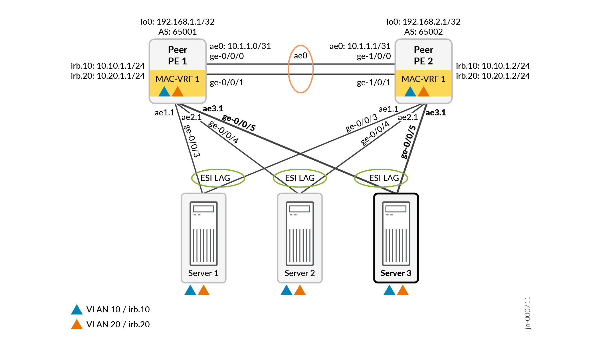
Add Configuration for a New Multihomed Server
Figure 4 shows the same topology as Figure 3 with an additional multihomed server.
The example configuration here shows how to add the new multihomed server, Server 3, that hosts the two VLANs VLAN 10 and VLAN 20.
- Simplified Configuration to Add a New Multihomed Server and ESI LAG
- Additional Generated Configuration for a New Multihomed Server and ESI LAG
Simplified Configuration to Add a New Multihomed Server and ESI LAG
In this example, both peer PE devices:
-
Link to the new server using interface ge-0/0/5.
-
Host the same VLANs, VLAN 10 and VLAN 20.
-
Automatically derive the ES identifier by default (using the
set interfaces aex esi auto-derive type-1-lacpcommand)
As a result, you can add the same additional easy EVPN LAG configuration
statements on both devices, and the commit script generates the same additional
configuration statements on both devices. You can also combine
server
server-name
options at the
[edit services evpn evpn-vxlan] hierarchy level into the
same command, as this configuration example shows. You only need to add one
configuration line item for this use case.
To add Server 3 with corresponding ESI LAG links, add the following single easy EVPN LAG configuration command to the existing simplified configuration on both Peer PE 1 and Peer PE 2:
set services evpn evpn-vxlan server SERVER_3 esi-lag-id 3 vlan-id-list [ 10 20 ] interface ge-0/0/5
Additional Generated Configuration for a New Multihomed Server and ESI LAG
The commit script generates the following additional configuration on both peer PE devices from the simplified configuration statements in Simplified Configuration to Add a New Multihomed Server and ESI LAG:
set interfaces ge-0/0/5 ether-options ethernet-switch-profile storm-control __SERVICES_EVPN_EVPN_VXLAN_STORM_CONTROL set interfaces ge-0/0/5 ether-options 802.3ad ae3 set interfaces ae3 vlan-tagging set interfaces ae3 encapsulation flexible-ethernet-services set interfaces ae3 esi auto-derive type-1-lacp set interfaces ae3 esi all-active set interfaces ae3 aggregated-ether-options lacp active set interfaces ae3 aggregated-ether-options lacp system-id 10:11:12:13:14:13 set interfaces ae3 unit 1 family ethernet-switching interface-mode trunk set interfaces ae3 unit 1 family ethernet-switching vlan members 10 set interfaces ae3 unit 1 family ethernet-switching vlan members 20 set routing-instances __SERVICES_EVPN_EVPN_VXLAN_MAC_VRF_1 interface ae3.1 set protocols loop-detect enhanced interface ae3.1 vlan-id 10 set protocols loop-detect enhanced interface ae3.1 loop-detect-action interface-down set protocols loop-detect enhanced interface ae3.1 transmit-interval 1s set protocols loop-detect enhanced interface ae3.1 revert-interval 60
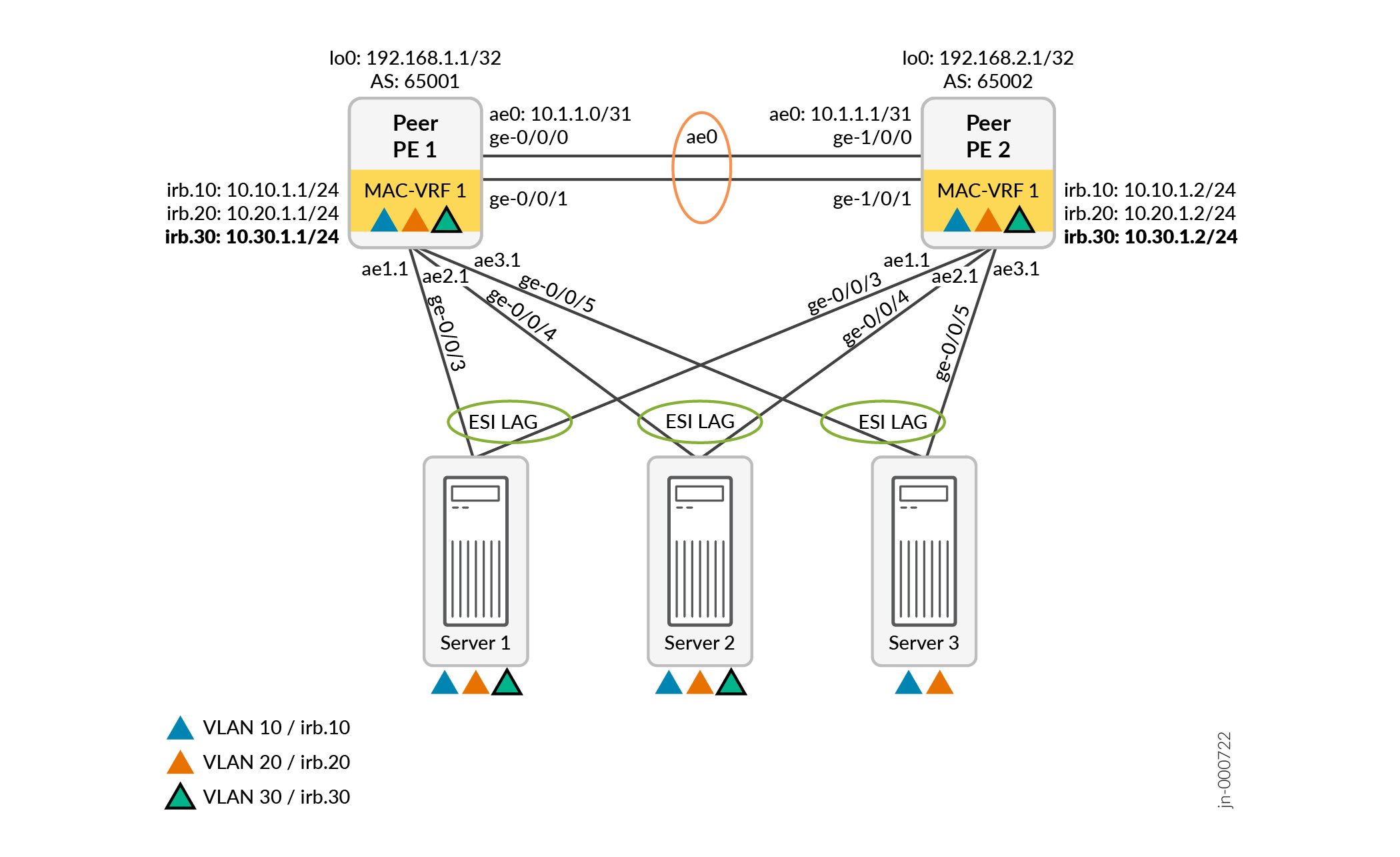
Add a New VLAN and IRB Interfaces
Figure 5 shows the same topology as Figure 5 with a new VLAN, VLAN 30, hosted only by Server 1 and Server 2.
Simplified Configuration to Add a New VLAN
To add VLAN 30 for Server 1 and Server 2 to the original configuration in Easy EVPN LAG Configuration with Multihomed Servers), add the following easy EVPN LAG configuration commands:
On both Peer PE devices:
set services evpn evpn-vxlan irb IRB_30 vlan-id 30 subnet-address inet 10.30.1.1/24
set services evpn evpn-vxlan server SERVER_1 vlan-id-list [ 30 ]
set services evpn evpn-vxlan server SERVER_2 vlan-id-list [ 30 ]
The simplified EVPN LAG configuration here is the same on both peer PE devices in this case because:
-
The commit script derives unique IRB interface subnet addresses for you using the provided subnet-address parameter.
-
We are adding the same VLAN on both devices.
Additional Generated Configuration for a New VLAN
The commit script generates the following additional configuration for VLAN 30:
Peer PE 1:
set interfaces ae1 unit 1 family ethernet-switching vlan members 30 set interfaces ae2 unit 1 family ethernet-switching vlan members 30 set interfaces irb unit 30 virtual-gateway-accept-data set interfaces irb unit 30 family inet address 10.30.1.1/24 virtual-gateway-address 10.30.1.254 set interfaces irb unit 30 virtual-gateway-v4-mac 00:00:5e:00:01:01 set routing-instances __SERVICES_EVPN_EVPN_VXLAN_MAC_VRF_1 vlans SERVICES_EVPN_EVPN_VXLAN_VLAN_30 vlan-id 30 set routing-instances __SERVICES_EVPN_EVPN_VXLAN_MAC_VRF_1 vlans SERVICES_EVPN_EVPN_VXLAN_VLAN_30 l3-interface irb.30 set routing-instances __SERVICES_EVPN_EVPN_VXLAN_MAC_VRF_1 vlans SERVICES_EVPN_EVPN_VXLAN_VLAN_30 vxlan vni 10030
Peer PE 2:
set interfaces ae1 unit 1 family ethernet-switching vlan members 30 set interfaces ae2 unit 1 family ethernet-switching vlan members 30 set interfaces irb unit 30 virtual-gateway-accept-data set interfaces irb unit 30 family inet address 10.30.1.2/24 virtual-gateway-address 10.30.1.254 set interfaces irb unit 30 virtual-gateway-v4-mac 00:00:5e:00:01:01 set routing-instances __SERVICES_EVPN_EVPN_VXLAN_MAC_VRF_1 vlans SERVICES_EVPN_EVPN_VXLAN_VLAN_30 vlan-id 30 set routing-instances __SERVICES_EVPN_EVPN_VXLAN_MAC_VRF_1 vlans SERVICES_EVPN_EVPN_VXLAN_VLAN_30 l3-interface irb.30 set routing-instances __SERVICES_EVPN_EVPN_VXLAN_MAC_VRF_1 vlans SERVICES_EVPN_EVPN_VXLAN_VLAN_30 vxlan vni 10030
Add a New Single-homed Server
Figure 6 adds a single-homed server, Server 4, that connects only to Peer PE 1. Server 4 hosts VLANs VLAN 10 and VLAN 20.
In the simplified configuration, you provide a single-home-id to identify single-homed servers links and the parameters related to that server. By default, the commit script uses aggregated Ethernet interface names starting with a base index of 1024 for links to single-homed servers. The commit script adds the single-home-id to that index, producing interface names that start with ae1025 (for single-home-id = 1).
- Simplified Configuration to Add a Single-homed Server
- Additional Generated Configuration for a Single-homed Server
Simplified Configuration to Add a Single-homed Server
To add single-homed Server 4 to the original configuration in Easy EVPN LAG Configuration with Multihomed Servers), add the following easy EVPN LAG configuration commands on Peer PE 1:
set services evpn evpn-vxlan server SERVER_4 single-home-id 1 vlan-id-list [ 10 20 ] interface ge-0/0/2
You can combine server server-name
options at the [edit services evpn evpn-vxlan] hierarchy
level, as this configuration example shows. As a result, you only need to
add one configuration line item for this use case.
Additional Generated Configuration for a Single-homed Server
The commit script generates the following additional configuration for Server 4 on Peer PE 1:
set interfaces ge-0/0/2 ether-options ethernet-switch-profile storm-control __SERVICES_EVPN_EVPN_VXLAN_STORM_CONTROL set interfaces ge-0/0/2 ether-options 802.3ad ae1025 set interfaces ae1025 vlan-tagging set interfaces ae1025 encapsulation flexible-ethernet-services set interfaces ae1025 aggregated-ether-options lacp active set interfaces ae1025 aggregated-ether-options lacp system-id 10:11:12:13:18:19 set interfaces ae1025 unit 1 family ethernet-switching interface-mode trunk set interfaces ae1025 unit 1 family ethernet-switching vlan members 10 set interfaces ae1025 unit 1 family ethernet-switching vlan members 20 set routing-instances __SERVICES_EVPN_EVPN_VXLAN_MAC_VRF_1 interface ae1025.1 set protocols loop-detect enhanced interface ae1025.1 vlan-id 10 set protocols loop-detect enhanced interface ae1025.1 loop-detect-action interface-down set protocols loop-detect enhanced interface ae1025.1 transmit-interval 1s set protocols loop-detect enhanced interface ae1025.1 revert-interval 60
Use OSPF for the Underlay Configuration
By default, the easy EVPN LAG configuration commit script generates a configuration that uses EBGP for the underlay peering between the peer PE devices. See the __SERVICES_EVPN_EVPN_VXLAN_EBGP_UNDERLAY EBGP group configuration statements in the example in Generated Configuration with Two Multihomed Servers.
If you want to use OSPF for the underlay peering instead, include the following option in your easy EVPN LAG configuration on both peer PE devices:
set services evpn device-attribute peer-to-peer underlay-connectivity ospf
With this option, in place of the default EBGP underlay configuration statements, the commit script generates an OSPF underlay peering configuration using the following default parameters (also refer to Table 2):
-
Aggregated Ethernet interface logical unit ae0.0
-
OSPF area 0.0.0.0
The commit script generates the following default OSPF underlay peering configuration on both peer PE devices:
set protocols ospf area 0.0.0.0 interface ae0.0 set protocols ospf area 0.0.0.0 interface lo0.0 passive
If you don't want to use the default EBGP or OSPF underlay peering configurations, you can set the following easy EVPN LAG configuration option:
set services evpn defaults-override no-underlay-config
With this option set, the commit script will not generate any underlay peering configuration. In that case, you must manually configure the desired underlay peering.
Use IBGP for the Overlay Configuration
By default, the easy EVPN LAG configuration commit script generates a configuration that uses EBGP for the overlay peering between the peer PE devices. See the __SERVICES_EVPN_EVPN_VXLAN_EBGP_OVERLAY EBGP group configuration statements in the example in Generated Configuration with Two Multihomed Servers.
If you want to use IBGP for the overlay peering instead, include the following option in your easy EVPN LAG configuration on both peer PE devices:
set services evpn device-attribute peer-to-peer overlay-connectivity ibgp
With this option, instead of the default EBGP overlay configuration, the commit script generates an IBGP overlay peering configuration using the following default or derived parameters (also refer to Table 2):
-
IBGP group name __SERVICES_EVPN_EVPN_VXLAN_IBGP_OVERLAY
-
AS number 65000
-
IBGP local address and peer neighbor address derived from
set services evpn device-attribute:-
peer-id peer-id -
loopback peer1-subnet peer1-subnet -
loopback peer2-subnet
                                                  peer2-subnet
-
For the example topology in Figure 3, the generated configuration is:
Peer PE 1:
set routing-options autonomous-system 65000
set protocols bgp group __SERVICES_EVPN_EVPN_VXLAN_IBGP_OVERLAY type internal
set protocols bgp group __SERVICES_EVPN_EVPN_VXLAN_IBGP_OVERLAY local-address 192.168.1.1
set protocols bgp group __SERVICES_EVPN_EVPN_VXLAN_IBGP_OVERLAY family inet-vpn unicast
set protocols bgp group __SERVICES_EVPN_EVPN_VXLAN_IBGP_OVERLAY family evpn signaling
set protocols bgp group __SERVICES_EVPN_EVPN_VXLAN_IBGP_OVERLAY neighbor 192.168.2.1
Peer PE 2:
set routing-options autonomous-system 65000
set protocols bgp group __SERVICES_EVPN_EVPN_VXLAN_IBGP_OVERLAY type internal
set protocols bgp group __SERVICES_EVPN_EVPN_VXLAN_IBGP_OVERLAY local-address 192.168.2.1
set protocols bgp group __SERVICES_EVPN_EVPN_VXLAN_IBGP_OVERLAY family inet-vpn unicast
set protocols bgp group __SERVICES_EVPN_EVPN_VXLAN_IBGP_OVERLAY family evpn signaling
set protocols bgp group __SERVICES_EVPN_EVPN_VXLAN_IBGP_OVERLAY neighbor 192.168.1.1