ON THIS PAGE
Example: Configuring VXLAN Data Center Interconnect Using EVPN
This example shows how to configure Virtual Extensible Local Area Network (VXLAN) data center connectivity using Ethernet VPN (EVPN) to leverage the benefits of EVPN as a data center interconnect (DCI) solution.
Requirements
This example uses the following hardware and software components:
Two provider edge (PE) devices in different data centers (DCs) acting as VXLAN tunnel endpoints (VTEPs).
Two customer edge (CE) devices.
Four host devices connected to each PE and CE device.
Before you begin:
Configure the device interfaces.
Configure an IGP, such as OSPF, on all the devices.
Establish a BGP session between the PE devices.
Configure MPLS and RSVP on the PE devices.
Configure PIM on the CE devices and in the routing instance of the PE devices.
Overview
VXLAN is a technology that provides intra data center connectivity using a tunneling scheme to stretch Layer 2 connections over an intervening Layer 3 network.
The Ethernet VPN (EVPN) technology, on the other hand, provides a solution for multipoint Layer 2 VPN services with advanced multihoming capabilities, using BGP control plane over MPLS/IP network.
Although several solutions are available for data center connectivity, the integration of EVPN with VXLAN provides an added advantage over the existing MPLS data center interconnect (DCI) technologies.
EVPN provides mechanisms for next generation DCI by adding extended control plane procedures to exchange Layer 2 MAC address and Layer 3 IP address information among the participating Data Center Border Routers (DCBRs). EVPN with its advanced features like active-active redundancy, aliasing, and mass MAC withdrawal helps in addressing the DCI challenges, such as seamless VM mobility and optimal IP routing, thus making it essential to provide VXLAN solutions over EVPN.
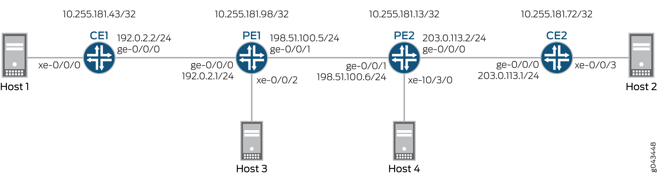
Figure 1 illustrates VXLAN data center interconnect using EVPN between devices PE1 and PE2 that are located in different data centers (DC1 and DC2, respectively). Each PE device is connected to one CE device and one host. All the PE and CE devices are configured under VLAN 10, and with the same VXLAN Network Identifier (VNI) of 10. Devices CE1 and PE1 belong to the multicast group of 192.168.1.10, and devices CE2 and PE2 belong to the multicast group of 172.16.1.10.
Topology
Configuration
CLI Quick Configuration
To quickly configure this example, copy the following commands, paste them into a text file, remove any line breaks, change any details necessary to match your network configuration, copy and paste the commands into the CLI at the [edit] hierarchy level, and then enter commit from configuration mode.
CE1
set interfaces xe-0/0/0 vlan-tagging
set interfaces xe-0/0/0 encapsulation flexible-ethernet-services
set interfaces xe-0/0/0 unit 10 encapsulation vlan-bridge
set interfaces xe-0/0/0 unit 10 vlan-id 10
set interfaces ge-0/0/0 unit 0 family inet address 192.0.2.2/24
set interfaces ge-0/0/0 unit 0 family mpls
set interfaces lo0 unit 0 family inet address 10.255.181.43/32
set protocols ospf area 0.0.0.0 interface ge-0/0/0.0
set protocols ospf area 0.0.0.0 interface lo0.0 passive
set protocols ospf area 0.0.0.0 interface fxp0.0 disable
set protocols pim rp local address 10.255.181.43
set protocols pim interface all
set bridge-domains evpn10 vlan-id 10
set bridge-domains evpn10 interface xe-0/0/0.10
set bridge-domains vxlan vni 10
set bridge-domains vxlan multicast-group 172.16.1.10
set bridge-domains vxlan encapsulate-inner-vlan
set bridge-domains vxlan decapsulate-accept-inner-vlan
CE2
set interfaces xe-0/0/3 vlan-tagging
set interfaces xe-0/0/3 encapsulation flexible-ethernet-services
set interfaces xe-0/0/3 unit 10 encapsulation vlan-bridge
set interfaces xe-0/0/3 unit 10 vlan-id 10
set interfaces lo0 unit 0 family inet address 10.255.181.72/32
set protocols ospf area 0 interface ge-0/0/0.0
set protocols ospf area 0 interface lo0.0 passive
set protocols ospf area 0 interface fxp0.0 disable
set protocols pim rp local address 10.255.181.72
set protocols pim interface all
set bridge-domains evpn10 vlan-id 10
set bridge-domains evpn10 interface xe-0/0/3.10
set bridge-domains vxlan vni 10
set bridge-domains vxlan multicast-group 192.168.1.10
set bridge-domains vxlan encapsulate-inner-vlan
set bridge-domains vxlan decapsulate-accept-inner-vlan
PE1
set interfaces xe-0/0/2 vlan-tagging
set interfaces xe-0/0/2 encapsulation flexible-ethernet-services
set interfaces xe-0/0/2 unit 10 encapsulation vlan-bridge
set interfaces xe-0/0/2 unit 10 vlan-id 10
set interfaces ge-0/0/0 unit 0 family inet address 192.0.2.1/24
set interfaces ge-0/0/1 mtu 1600
set interfaces ge-0/0/1 unit 0 family inet address 198.51.100.5/24
set interfaces ge-0/0/1 unit 0 family mpls
set interfaces lo0 unit 1 family inet address 10.255.181.98/32
set protocols rsvp interface all
set protocols mpls no-cspf
set protocols mpls label-switched-path to-PE2 to 10.255.181.13
set protocols mpls interface all
set protocols bgp family evpn signaling
set protocols bgp group ibgp type internal
set protocols bgp group ibgp neighbor 10.255.181.13 local-address 10.255.181.98
set protocols ospf area 0 interface ge-0/0/1.0
set protocols ospf area 0 interface fxp0.0 disable
set protocols ospf area 0 interface lo0.0 passive
set routing-instances evpn10 vtep-source-interface lo0.0
set routing-instances evpn10 instance-type evpn
set routing-instances evpn10 vlan-id 10
set routing-instances evpn10 interface xe-0/0/2.10
set routing-instances evpn10 vxlan vni 10
set routing-instances evpn10 vxlan multicast-group 172.16.1.10
set routing-instances evpn10 vxlan encapsulate-inner-vlan
set routing-instances evpn10 vxlan decapsulate-accept-inner-vlan
set routing-instances evpn10 route-distinguisher 10.255.181.98:10
set routing-instances evpn10 vrf-target target:10:10
set routing-instances evpn10 protocols evpn
set routing-instances evpna instance-type vrf
set routing-instances evpna route-distinguisher 10.255.181.98:11
set routing-instances evpna vrf-target target:65000:11
set routing-instances evpna vrf-table-label
set routing-instances vrf instance-type vrf
set routing-instances vrf interface ge-0/0/0.0
set routing-instances vrf interface lo0.0
set routing-instances vrf route-distinguisher 10.255.181.98:100
set routing-instances vrf vrf-target target:100:100
set routing-instances vrf protocols ospf area 0 interface lo0.0 passive
set routing-instances vrf protocols ospf area 0 interface ge-0/0/0.0
set routing-instances vrf protocols pim rp static address 10.255.181.43
set routing-instances vrf protocols pim interface all
PE2
set interfaces ge-0/0/1 mtu 1600
set interfaces ge-0/0/1 unit 0 family inet address 198.51.100.6/24
set interfaces ge-0/0/1 unit 0 family mpls
set interfaces xe-10/3/0 vlan-tagging
set interfaces xe-10/3/0 encapsulation flexible-ethernet-services
set interfaces xe-10/3/0 unit 10 encapsulation vlan-bridge
set interfaces xe-10/3/0 unit 10 vlan-id 10
set interfaces lo0 unit 1 family inet address 10.255.181.13/32
set protocols rsvp interface all
set protocols mpls no-cspf
set protocols mpls label-switched-path to-PE1 to 10.255.181.98
set protocols mpls interface all
set protocols bgp family evpn signaling
set protocols bgp group ibgp type internal
set protocols bgp group ibgp neighbor 10.255.181.98 local-address 10.255.181.13
set protocols ospf area 0 interface ge-0/0/1.0
set protocols ospf area 0 interface fxp0.0 disable
set protocols ospf area 0 interface lo0.0 passive
set routing-instances evpn10 vtep-source-interface lo0.0
set routing-instances evpn10 instance-type evpn
set routing-instances evpn10 vlan-id 10
set routing-instances evpn10 interface xe-10/3/0.10
set routing-instances evpn10 vxlan vni 10
set routing-instances evpn10 vxlan multicast-group 192.168.1.10
set routing-instances evpn10 vxlan encapsulate-inner-vlan
set routing-instances evpn10 vxlan decapsulate-accept-inner-vlan
set routing-instances evpn10 route-distinguisher 10.255.181.13:10
set routing-instances evpn10 vrf-target target:10:10
set routing-instances evpn10 protocols evpn
set routing-instances evpna instance-type vrf
set routing-instances evpna route-distinguisher 10.255.181.13:11
set routing-instances evpna vrf-target target:65000:11
set routing-instances evpna vrf-table-label
set routing-instances vrf instance-type vrf
set routing-instances vrf interface xe-10/3/0.0
set routing-instances vrf interface lo0.0
set routing-instances vrf route-distinguisher 10.255.181.13:100
set routing-instances vrf vrf-target target:100:100
set routing-instances vrf protocols ospf area 0 interface lo0.0 passive
set routing-instances vrf protocols ospf area 0 interface xe-10/3/0.0
set routing-instances vrf protocols pim rp static address 10.255.181.72
set routing-instances vrf protocols pim interface all
Procedure
Step-by-Step Procedure
The following example requires you to navigate various levels in the configuration hierarchy. For information about navigating the CLI, see Using the CLI Editor in Configuration Mode.
To configure Device CE1:
Repeat this procedure for Device CE2 after modifying the appropriate interface names, addresses, and other parameters.
Configure Device CE1 interfaces.
[edit interfaces]
user@CE1# set xe-0/0/0 vlan-tagging
user@CE1# set xe-0/0/0 encapsulation flexible-ethernet-services
user@CE1# set xe-0/0/0 unit 10 encapsulation vlan-bridge
user@CE1# set xe-0/0/0 unit 10 vlan-id 10
user@CE1# set ge-0/0/0 unit 0 family inet address 192.0.2.2/24
user@CE1# set ge-0/0/0 unit 0 family mpls
user@CE1# set lo0 unit 0 family inet address 10.255.181.43/32
Enable OSPF on Device CE1 interface, excluding the management interface.
[edit protocols]
user@CE1# set ospf area 0.0.0.0 interface ge-0/0/0.0
user@CE1# set ospf area 0.0.0.0 interface lo0.0 passive
user@CE1# set ospf area 0.0.0.0 interface fxp0.0 disable
Enable PIM on all the interfaces of Device CE1.
[edit protocols]
user@CE1# set pim rp local address 10.255.181.43
user@CE1# set pim interface all
Configure an EVPN bridge domain, and assign VLAN ID and interface.
[edit bridge-domains]
user@CE1# set evpn10 vlan-id 10
user@CE1# set evpn10 interface xe-0/0/0.10
Configure a VXLAN bridge domain, assign VXLAN ID, a multicast group address, and encapsulation and decapsulation parameters.
[edit bridge-domains]
user@CE1# set vxlan vni 10
user@CE1# set vxlan multicast-group 172.16.1.10
user@CE1# set vxlan encapsulate-inner-vlan
user@CE1# set vxlan decapsulate-accept-inner-vlan
Step-by-Step Procedure
To configure Device PE1:
Repeat this procedure for Device PE2 after modifying the appropriate interface names, addresses, and other parameters.
Configure Device PE1 interfaces.
[edit interfaces]
user@PE1# set xe-0/0/2 vlan-tagging
user@PE1# set xe-0/0/2 encapsulation flexible-ethernet-services
user@PE1# set xe-0/0/2 unit 10 encapsulation vlan-bridge
user@PE1# set xe-0/0/2 unit 10 vlan-id 10
user@PE1# set ge-0/0/0 unit 0 family inet address 192.0.2.1/24
user@PE1# set ge-0/0/1 mtu 1600
user@PE1# set ge-0/0/1 unit 0 family inet address 198.51.100.5/24
user@PE1# set ge-0/0/1 unit 0 family mpls
user@PE1# set lo0 unit 1 family inet address 10.255.181.98/32
Enable MPLS and RSVP on all the interfaces of Device PE1.
[edit protocols]
user@PE1# set rsvp interface all
user@PE1# set mpls no-cspf
user@PE1# set mpls interface all
Configure a label-switched-path from Device PE1 to Device PE2.
[edit protocols]
user@PE1# set mpls label-switched-path to-PE2 to 10.255.181.13
Configure internal BGP peering between Devices PE1 and PE2, and enable EVPN signaling for the BGP session.
[edit protocols]
user@PE1# set bgp family evpn signaling
user@PE1# set bgp group ibgp type internal
user@PE1# set bgp group ibgp neighbor 10.255.181.13 local-address 10.255.181.98
Configure OSPF on Device PE1 interface, excluding the management interface.
[edit protocols]
user@PE1# set ospf area 0 interface ge-0/0/1.0
user@PE1# set ospf area 0 interface fxp0.0 disable
user@PE1# set ospf area 0 interface lo0.0 passive
Configure an EVPN routing instance, assign the VXLAN tunnel endpoint source interface, VLAN ID, assign route distinguisher and VRF target values, and assign Device PE1 interface to the routing instance.
[edit routing-instances]
user@PE1# set evpn10 vtep-source-interface lo0.0
user@PE1# set evpn10 instance-type evpn
user@PE1# set evpn10 vlan-id 10
user@PE1# set evpn10 interface xe-0/0/2.10
user@PE1# set evpn10 route-distinguisher 10.255.181.13:10
user@PE1# set evpn10 vrf-target target:10:10
user@PE1# set evpn10 protocols evpn
Assign the VXLAN ID, multicast group address, and encapsulation and decapsulation parameters for the EVPN routing instance.
[edit routing-instances]
user@PE1# set evpn10 vxlan vni 10
user@PE1# set evpn10 vxlan multicast-group 172.16.1.10
user@PE1# set evpn10 vxlan encapsulate-inner-vlan
user@PE1# set evpn10 vxlan decapsulate-accept-inner-vlan
Configure the first VPN routing and forwarding (VRF) routing instance, and assign route distinguisher and vrf-target values.
[edit routing-instances]
user@PE1# set evpna instance-type vrf
user@PE1# set evpna route-distinguisher 10.255.181.13:11
user@PE1# set evpna vrf-target target:65000:11
user@PE1# set evpna vrf-table-label
Configure the second VRF routing instance, and assign Device PE1 interfaces, route distinguisher and vrf-target values.
[edit routing-instances]
user@PE1# set vrf instance-type vrf
user@PE1# set vrf interface ge-0/0/0.0
user@PE1# set vrf interface lo0.0
user@PE1# set vrf route-distinguisher 10.255.181.13:100
user@PE1# set vrf vrf-target target:100:100
Configure OSPF and PIM protocols for the second VRF routing instance.
[edit routing-instances]
user@PE1# set vrf protocols ospf area 0 interface lo0.0 passive
user@PE1# set vrf protocols ospf area 0 interface ge-0/0/0.0
user@PE1# set vrf protocols pim rp static address 10.255.181.43
user@PE1# set vrf protocols pim interface all
Results
From configuration mode, confirm your configuration by entering the show interfaces, show protocols, and show routing-instances commands. If the output does not display the intended configuration, repeat the instructions in this example to correct the configuration.
CE1
user@CE1# show interfaces
xe-0/0/0 {
    vlan-tagging;
    encapsulation flexible-ethernet-services;
    unit 10 {
        encapsulation vlan-bridge;
        vlan-id 10;
    }
}
ge-0/0/0 {
    unit 0 {
        family inet {
            address 192.0.2.2/24;
        }
        family mpls;
    }
}
lo0 {
    unit 0 {
        family inet {
            address 10.255.181.43/32;
        }
    }
}
user@CE1# show protocols
ospf {
    area 0.0.0.0 {
        interface ge-0/0/0.0;
        interface lo0.0 {
            passive;
        }
        interface fxp0.0 {
            disable;
        }
    }
}
pim {
    rp {
        local {
            address 10.255.181.43;
        }
    }
    interface all;
}
user@CE1# show bridge-domains
evpn10 {
    vlan-id 10;
    interface xe-0/0/0.10;
    vxlan {
        vni 10;
        multicast-group 172.16.1.10;
        encapsulate-inner-vlan;
        decapsulate-accept-inner-vlan;
    }
}
PE1
user@PE1# show interfaces
xe-0/0/2 {
    vlan-tagging;
    encapsulation flexible-ethernet-services;
    unit 10 {
        encapsulation vlan-bridge;
        vlan-id 10;
    }
}
ge-0/0/0 {
    unit 0 {
        family inet {
            address 192.0.2.1/24;
        }
    }
}
ge-0/0/1 {
    mtu 1600;
    unit 0 {
        family inet {
            address 198.51.100.5/24;
        }
        family mpls;
    }
}
lo0 {
    unit 1 {
        family inet {
            address 10.255.181.98/32;
        }
    }
}
user@PE1# show protocols
rsvp {
    interface all;
}
mpls {
    no-cspf;
    label-switched-path to-PE2 {
        to 10.255.181.13;
    }
    interface all;
}
bgp {
    family evpn {
        signaling;
    }
    group ibgp {
        type internal;
        neighbor 10.255.181.13 {
            local-address 10.255.181.98;
        }
    }
}
ospf {
    area 0.0.0.0 {
        interface ge-0/0/1.0;
        interface fxp0.0 {
            disable;
        }
        interface lo0.0 {
            passive;
        }
    }
}
user@PE1# show routing-instances
evpn10 {
    vtep-source-interface lo0.0;
    instance-type evpn;
    vlan-id 10;
    interface xe-0/0/2.10;
    vxlan {
        vni 10;
        multicast-group 172.16.1.10;
        encapsulate-inner-vlan;
        decapsulate-accept-inner-vlan;
    }
    route-distinguisher 10.255.181.13:10;
    vrf-target target:10:10;
    protocols {
        evpn;
    }
}
evpna {
    instance-type vrf;
    route-distinguisher 10.255.181.98:11;
    vrf-target target:65000:11;
    vrf-table-label;
}
vrf {
    instance-type vrf;
    interface ge-0/0/0.0;
    interface lo0.0;
    route-distinguisher 10.255.181.98:100;
    vrf-target target:100:100;
    protocols {
        ospf {
            area 0.0.0.0 {
                interface lo0.0 {
                    passive;
                }
                interface ge-0/0/0.0;
            }
        }
        pim {
            rp {
                static {
                    address 10.255.181.43;
                }
            }
            interface all;
        }
    }
}
Verification
Confirm that the configuration is working properly.
Verifying MAC Learning
Purpose
Verify the bridging and EVPN MAC table entries on CE and PE devices.
Action
On Device CE1, determine the bridging MAC table entries.
From operational mode, run the show bridge mac-table command.
user@CE1> show bridge mac-table

 MAC flags       (S -static MAC, D -dynamic MAC, L -locally learned, C -Control MAC
     O -OVSDB MAC, SE -Statistics enabled, NM -Non configured MAC, R -Remote PE MAC)

 Routing instance : default-switch
  Bridging domain : evpn10, VLAN : 10
    MAC                 MAC      Logical          NH     RTR
    address             flags    interface        Index  ID
    00:00:00:00:00:11   D        xe-0/0/0.10
    00:00:00:00:00:22   D        vtep.32769
On Device PE1, determine the EVPN MAC table entries.
From operational mode, run the show evpn mac-table command.
user@PE1> show evpn mac-table

 MAC flags       (S -static MAC, D -dynamic MAC, L -locally learned, C -Control MAC
     O -OVSDB MAC, SE -Statistics enabled, NM -Non configured MAC, R -Remote PE MAC)

 Routing instance : evpn10
  Bridging domain : __evpn10__, VLAN : 10
    MAC                 MAC      Logical          NH     RTR
    address             flags    interface        Index  ID
    00:00:00:00:00:11   D        vtep.32769
    00:00:00:00:00:22   DC                        1048576 1048576
Meaning
The bridging and EVPN MAC tables have learned the VLAN configurations.
Verifying PIM Reachability
Purpose
Verify that the PIM configuration is working properly on the CE and PE devices.
Action
On Device CE1, verify PIM configuration.
From operational mode, run the show pim rps extensive command.
user@CE1> show pim rps extensive
 Instance: PIM.master

 address-family INET

 RP: 10.255.181.43
 Learned via: static configuration
 Mode: Sparse
 Time Active: 00:06:08
 Holdtime: 150
 Device Index: 161
 Subunit: 32769
 Interface: pd-0/2/0.32769
 Static RP Override: Off
 Group Ranges:
         224.0.0.0/4
 Register State for RP:
 Group           Source          FirstHop        RP Address      State    Timeout
 172.16.1.10      203.1.113.11       203.1.113.11       10.255.181.43   Receive      171

 address-family INET6
From operational mode, run the show pim join extensive command.
user@CE1> show pim join extensive
 Instance: PIM.master Family: INET
 R = Rendezvous Point Tree, S = Sparse, W = Wildcard

 Group: 172.16.1.10
     Source: *
     RP: 10.255.181.43
     Flags: sparse,rptree,wildcard
     Upstream interface: Local
     Upstream neighbor: Local
     Upstream state: Local RP
     Uptime: 00:06:08
     Downstream neighbors:
         Interface: ge-0/0/0.0 (assert winner)
             192.0.2.1 State: Join Flags: SRW Timeout: 201
             Uptime: 00:05:08 Time since last Join: 00:00:08
             Assert Winner: 192.0.2.2 Metric: 0 Pref: 2147483648 Timeout: 82
         Interface: Pseudo-VXLAN
     Number of downstream interfaces: 2

 Group: 172.16.1.10
     Source: 10.255.181.43
     Flags: sparse,spt
     Upstream interface: Local
     Upstream neighbor: Local
     Upstream state: Local Source, Local RP, No Prune to RP
     Keepalive timeout: 338
     Uptime: 00:04:15
     Downstream neighbors:
         Interface: ge-0/0/0.0
             192.0.2.1 State: Join Flags: S Timeout: 201
             Uptime: 00:04:15 Time since last Join: 00:00:08
         Interface: Pseudo-VXLAN
     Number of downstream interfaces: 2

 Group: 172.16.1.10
     Source: 203.1.113.11
     Flags: sparse,spt
     Upstream interface: ge-0/0/0.0
     Upstream neighbor: 192.0.2.1 (assert winner)
     Upstream state: Local RP, Join to Source, No Prune to RP
     Keepalive timeout: 338
     Uptime: 00:04:15
     Downstream neighbors:
         Interface: ge-0/0/0.0 (pruned)
             192.0.2.1 State: Prune Flags: SR Timeout: 201
             Uptime: 00:04:15 Time since last Prune: 00:00:08
             Assert Winner: 192.0.2.1 Metric: 0 Pref: 0 Timeout: 179
         Interface: Pseudo-VXLAN
     Number of downstream interfaces: 2

 Instance: PIM.master Family: INET6
 R = Rendezvous Point Tree, S = Sparse, W = Wildcard
Meaning
The device reachability using PIM is working as configured.
Verifying VXLAN Reachability
Purpose
Verify the connectivity between the VTEPs in the different data centers.
Action
From the operational mode, run the show l2-learning vxlan-tunnel-end-point source, show l2-learning vxlan-tunnel-end-point remote, and show interfaces vtep commands.
user@PE1> show l2-learning vxlan-tunnel-end-point source
 Logical System Name       Id  SVTEP-IP         IFL   L3-Idx
        <default>                 0   203.1.113.11        lo0.0    7
     L2-RTT                   Bridge Domain              VNID     MC-Group-IP

evpn10 __evpn10__ 10 172.16.1.10user@PE2> show l2-learning vxlan-tunnel-end-point source
Logical System Name Id SVTEP-IP IFL L3-Idx
<default> 0 203.1.113.12 lo0.0 7
L2-RTT Bridge Domain VNID MC-Group-IP
evpn10 __evpn10__ 10 192.168.1.10user@PE1> show l2-learning vxlan-tunnel-end-point remote
Logical System Name Id SVTEP-IP IFL L3-Idx
<default> 0 203.1.113.11 lo0.0 7
RVTEP-IP IFL-Idx NH-Id
10.255.181.43 2684275660 2684275660
VNID MC-Group-IP
10 172.16.1.10
user@PE2> show l2-learning vxlan-tunnel-end-point remote
 Logical System Name       Id  SVTEP-IP         IFL   L3-Idx
        <default>                 0   203.1.113.12        lo0.0    7
  RVTEP-IP         IFL-Idx   NH-Id
  10.255.181.98    351       661
     VNID          MC-Group-IP
10 192.168.1.10user@PE1> show interfaces vtep
Physical interface: vtep, Enabled, Physical link is Up
Interface index: 133, SNMP ifIndex: 508
Type: Software-Pseudo, Link-level type: VxLAN-Tunnel-Endpoint, MTU: 1600, Speed: Unlimited
Device flags : Present Running
Interface flags: SNMP-Traps
Link type : Full-Duplex
Link flags : None
Last flapped : Never
Input packets : 0
Output packets: 0
Logical interface vtep.32768 (Index 339) (SNMP ifIndex 560)
Flags: Up SNMP-Traps Encapsulation: ENET2
Ethernet segment value: 00:00:00:00:00:00:00:00:00:00, Mode: Single-homed, Multi-homed status: Forwarding
VXLAN Endpoint Type: Source, VXLAN Endpoint Address: 203.1.113.11, L2 Routing Instance: evpn10, L3 Routing Instance: vrf
Input packets : 0
Output packets: 0
Logical interface vtep.32769 (Index 341) (SNMP ifIndex 567)
Flags: Up SNMP-Traps Encapsulation: ENET2
VXLAN Endpoint Type: Remote, VXLAN Endpoint Address: 10.255.181.43, L2 Routing Instance: evpn10, L3 Routing Instance: vrf
Input packets : 143746
Output packets: 95828
Protocol bridge, MTU: 1600
Flags: Trunk-ModeMeaning
The output shows the correct tunnel source IP address (assigned to the loopback interface), VLAN, and multicast group for the VXLAN. Device PE1 is reachable because its IP address (the address assigned to the loopback interface) appears in the output. The output also shows that the VXLAN (VNI 10) and corresponding multicast group are configured correctly on the remote VTEP, Device PE2.