VXLAN Data Center Interconnect Using EVPN Overview
Ethernet VPN (EVPN) technology can be used to interconnect Virtual Extensible Local Area Network (VXLAN) networks over an MPLS/IP network to provide data center connectivity. This is done through Layer 2 intra-subnet connectivity and control-plane separation among the interconnected VXLAN networks.
The following sections describe the technology and implementation overview of integrating EVPN with VXLAN to be used as a data center interconnect (DCI) solution.
Technology Overview of VXLAN-EVPN Integration for DCI
The following sections provide a conceptual overview of VXLAN, EVPN, the need for their integration for DCI and the resulting benefits.
- Understanding VXLAN
- Understanding EVPN
- VXLAN-EVPN Integration Overview
- VXLAN-EVPN Packet Format
- VXLAN-EVPN Packet Walkthrough
Understanding VXLAN
Virtual Extensible Local Area Network (VXLAN) is a Layer 3 encapsulation protocol that enables MX Series routers to push Layer 2 or Layer 3 packets through a VXLAN tunnel to a virtualized data center or the Internet. Communication is established between two virtual tunnel endpoints (VTEPs), which can be end hosts or network switches or routers, that encapsulate and de-encapsulate the virtual machine (VM) traffic into a VXLAN header.
VXLAN is often described as an overlay technology because it allows you to stretch Layer 2 connections over an intervening Layer 3 network by encapsulating (tunneling) Ethernet frames in a VXLAN packet that includes IP addresses. This feature of VXLAN addresses the requirements of a multi-tenant datacenter, where each tenant’s VM might be sharing the physical server with other tenants that are distributed across physical servers within or across different data centers, by meeting the growing need to provide seamless Layer 2 connectivity between all the VMs owned by a tenant, in addition to isolating each tenant’s traffic for security and potential MAC address overlaps.
VXLAN tunnels are created between the physical servers by the hypervisors. Since a physical server can host multiple tenants, each hypervisor creates multiple VXLAN tunnels.
VXLAN is a technology that allows you to segment your networks (as VLANs do) but that also solves the scaling limitation of VLANs and provides benefits that VLANs cannot. Some of the important benefits of using VXLANs include:
-
You can theoretically create as many as 16 million VXLANs in an administrative domain (as opposed to 4094 VLANs on a Juniper Networks device).
MX Series routers support as many as 32K VXLANs. This means that VXLANs provide network segmentation at the scale required by cloud builders to support very large numbers of tenants.
-
You can enable migration of virtual machines between servers that exist in separate Layer 2 domains by tunneling the traffic over Layer 3 networks. This functionality allows you to dynamically allocate resources within or between data centers without being constrained by Layer 2 boundaries or being forced to create large or geographically stretched Layer 2 domains.
Understanding EVPN
EVPN is a new standards-based technology that provides virtual multi-point bridged connectivity between different Layer 2 domains over an IP or IP/MPLS backbone network. Similar to other VPN technologies, such as IPVPN and VPLS, EVPN instances (EVIs) are configured on PE routers to maintain logical service separation between customers. The PEs connect to CE devices which can be a router, switch, or host. The PE routers then exchange reachability information using Multi-Protocol BGP (MP-BGP) and encapsulated traffic is forwarded between PEs. Because elements of the architecture are common with other VPN technologies, EVPN can be seamlessly introduced and integrated into existing service environments.
The EVPN technology provides mechanisms for next generation Data Center Interconnect (DCI) by adding extended control plane procedures to exchange the Layer 2 (MAC address) and Layer 3 (IP address) information among the participating Data Center Border Routers (DCBRs). These features help to address some of the DCI challenges, such as seamless VM mobility and optimal IP routing. Seamless VM mobility refers to the challenge of Layer 2 extension and maintaining connectivity in the face of VM mobility, and optimal IP routing refers to the challenge of supporting default gateway behavior for a VM's outbound traffic and triangular routing avoidance of a VM's inbound traffic.
The EVPN technology is used by the data center operator to offer multi-tenancy, flexible and resilient services that can be extended on demand. This flexibility and resiliency can require using compute resources among different physical data centers for a single service (Layer 2 extension), and VM motion.
EVPN supports all-active multihoming which allows a CE device to connect to two or more PE routers such that traffic is forwarded using all of the links between the devices. This enables the CE to load balance traffic to the multiple PE routers. More importantly, it allows a remote PE to load balance traffic to the multihomed PEs across the core network. This load balancing of traffic flows between data centers is known as aliasing. EVPN also has mechanisms that prevent the looping of broadcast, unknown unicast, and multicast (BUM) traffic in an all-active multi-homed topology.
Multihoming provides redundancy in the event that an access link or one of the PE routers fails. In either case, traffic flows from the CE towards the PE use the remaining active links. For traffic in the other direction, the remote PE updates its forwarding table to send traffic to the remaining active PEs connected to the multihomed Ethernet segment. EVPN provides a fast convergence mechanism so that the time it takes to make this adjustment is independent of the number of MAC addresses learned by the PE.
EVPN’s MP-BGP control plane allows live virtual machines to be dynamically moved from one data center to another, also known as VM motion. After a VM is moved to a destination server/hypervisor it transmits a Gratuitous ARP that updates the Layer 2 forwarding table of the PE at the destination data center. The PE then transmits a MAC route update to all remote PEs, which in turn update their forwarding tables. In this manner, an EVPN tracks the movement of the VM, also known as MAC Mobility. EVPN also has mechanisms to detect and stop MAC flapping.
The EVPN technology, similar to Layer 3 MPLS VPN, is a technology that introduces the concept of routing MAC addresses using MP-BGP over MPLS core. Some of the important benefits of using EVPNs include:
-
Ability to have a dual active multihomed edge device.
-
Provides load balancing across dual-active links.
-
Provides MAC address mobility.
-
Provides multi-tenancy.
-
Provides aliasing.
-
Enables fast convergence.
VXLAN-EVPN Integration Overview
VXLAN defines a tunneling scheme to overlay Layer 2 networks on top of Layer 3 networks. It allows for optimal forwarding of Ethernet frames with support for multipathing of unicast and multicast traffic with the use of UDP/IP encapsulation for tunneling, and is mainly used for intra-datacenter site connectivity.
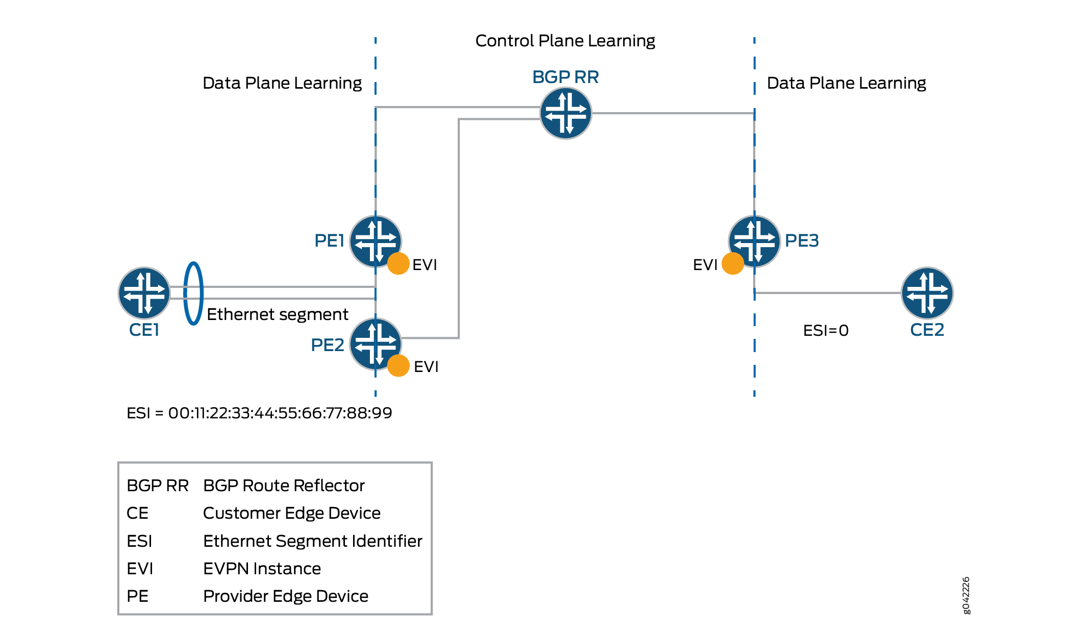
On the other hand, a unique characteristic of EVPN is that MAC address learning between PE devices occurs in the control plane. A new MAC address detected from a CE device is advertised by the local PE, using MP-BGP, to all the remote PE devices. This method differs from existing Layer 2 VPN solutions such as VPLS, which learn by flooding unknown unicast in the data plane. This control plane-based MAC learning method is the key enabler of the many useful features provided by EVPN.
Because MAC learning is handled in the control plane, this leaves EVPN with the flexibility to support different data plane encapsulation technologies between PEs. This is important because not every backbone network may be running MPLS, especially in Enterprise networks.
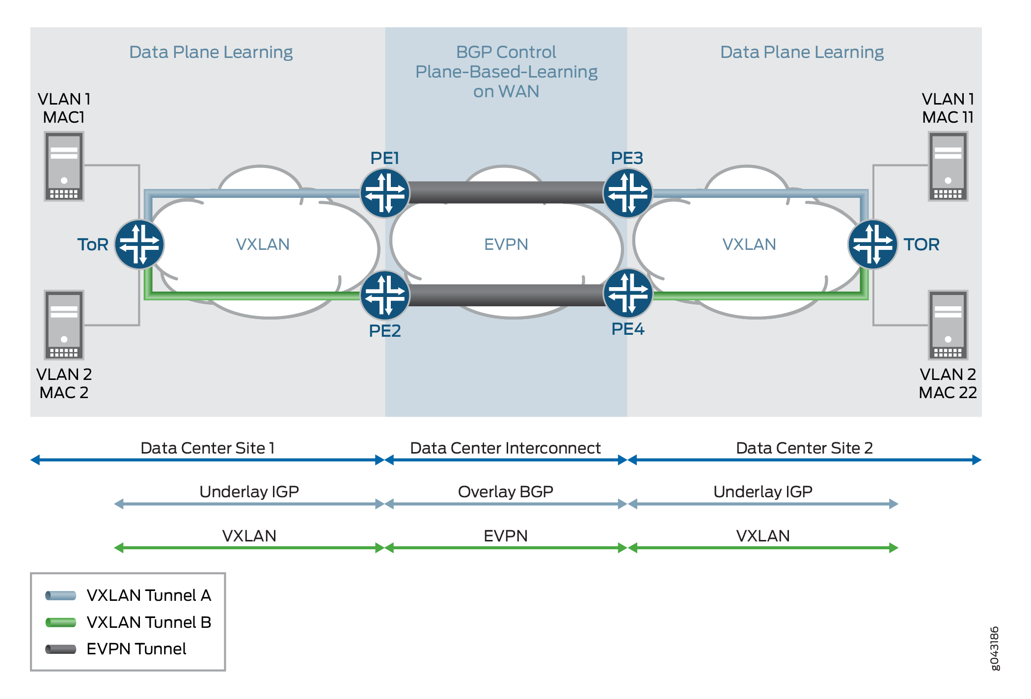
There is a lot of interest in EVPN today because it addresses many of the challenges faced by network operators that are building data centers to offer cloud and virtualization services. The main application of EVPN is Data Center Interconnect (DCI), the ability to extend Layer 2 connectivity between different data centers that are deployed to improve the performance of delivering application traffic to end users and for disaster recovery.
Although there are various DCI technologies available, EVPN has an added advantage over the other MPLS technologies because of its unique features, such as active-active redundancy, aliasing, and mass MAC withdrawal. As a result, to provide a solution for DCI, VXLAN is integrated with EVPN.
Every VXLAN network, which is connected to the MPLS or IP core, runs an independent instance of the IGP control plane. Each PE device participates in the IGP control plane instance of its VXLAN network. Here, each customer is a datacenter so it has its own virtual router for VXLAN underlay.
Each PE node may terminate the VXLAN data plane encapsulation where each VNI or VSID is mapped to a bridge domain. The PE router performs data plane learning on the traffic received from the VXLAN network.
Each PE node implements EVPN to distribute the client MAC addresses learnt over the VXLAN tunnel into BGP. Each PE node encapsulates the VXLAN or Ethernet frames with MPLS when sending the packets over the MPLS core and with the VXLAN tunnel header when sending the packets over the VXLAN network
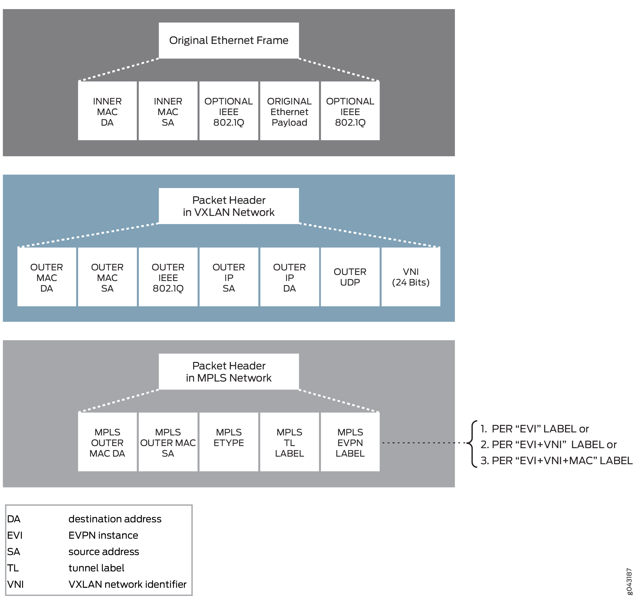
VXLAN-EVPN Packet Format
The VXLAN and EVPN packet format is as follows:
VXLAN-EVPN Packet Walkthrough
The following sections describe the packet walkthrough for two types of traffic between the VXLAN and EVPN networks:
BUM Traffic Handling
The VXLAN to EVPN BUM traffic from VXLAN segment1 to VXLAN segment2 over the EVPN cloud is handled as follows:
-
0—On boot up, Server A wants to send traffic to Server B. Because Server A does not have an ARP binding for Server B in its ARP table, Server A builds an ARP broadcast request and sends it.
The contents of the ARP packets are as follows:
-
VLAN ID = VLAN 10
-
Source MAC= MAC1
-
Destination MAC = ff.ff.ff.ff.ff.ff
-
Source IP address = IP address of Server A or VM IP address
-
Destination IP address = IP address of Server B
-
Ether type of packet = 0x0806
A Layer 2 frame is sent to top-of-rack (TOR) switch TOR A, which is VXLAN enabled.
-
-
1—The ARP request (broadcast) frame is received by switch TOR A. TOR A is the originator and terminator of the VXLAN VTEP for VNI 1000. The VTEP for VXLAN 1000 is part of the broadcast domain for Server A VLAN 10.
After receiving the frame, TOR A performs ingress processing, including ingress packet classification. Based on the incoming VLAN in the packet, TOR A classifies the packet into one of the IFL under a given port. The family of this IFL is a bridge family. Based on the IFL bridge family, the bridge domain ID is identified.
After the bridge domain is identified, TOR A learns the incoming frame source MAC so that MAC A becomes reachable through this IFL. Because the frame is a broadcast frame, TOR A needs to send the frame to all the members of the broadcast domain (other than the member on which the frame was received). One of the members of the broadcast domain is the VTEP for VNI 1000. To send the frame on the VXLAN segment, TOR A completes VXLAN BUM next hop processing on the frame. The next hop pushes the VXLAN header.
The contents of the VXLAN header is as follows:
-
Source MAC Address = MAC Address or source IP address interface
-
Destination MAC address = Multicast MAC address
-
Source IP address = 10.10.10.1
-
Destination IP Address = Multicast group address (226.0.39.16)
-
Source UDP port = Calculated based on the hash on the incoming frame header
-
Destination UDP port = 4789 (well known port for VXLAN tunnel)
After building the VXLAN encapsulated frame, TOR A sends the frame to Router PE2.
-
-
2—Router PE2 receives the VXLAN frame and identifies the frame as a VXLAN frame by looking at the well-known destination UDP port. This VXLAN frame’s VNI ID is used for bridge domain identification. After router PE2 identifies the bridge domain, PE2 completes MAC learning for the inner source MAC to the outer source IP address (MACA to 10.10.10.1 mapping). After the mapping is done, the VXLAN decapsulation next hop processing removes the VXLAN header to terminate the VXLAN tunnel.
-
3A—After MAC learning is done, the learnt source MAC (MAC1 to outer source IP) is sent to the L2ALD. This MAC route is sent by L2ALD to RPD for control plane learning of this MAC through BGP MAC route advertisement to BGP peers. After the BGP peer routers receive the MAC route advertisement, the routers install this MAC reachability (MACA, MPLS LABEL L1) in the bridge-domain table.
-
3—The given bridge domain points to the multicast next hop route for forwarding the packet over the EVPN cloud. This next hop pushes the service label (multicast MPLS label associated with VNI per peer ID, bridge domain, label is the per peer ID and VNI ID). The MPLS packet is formed and sent over the MPLS cloud.
-
4—Router PE4 receives the frame as an MPLS packet. Here, PE4 identifies the bridge domain by looking up the MPLS label L1 in the mpls.0 table. MPLS lookup points to the table next hop for the bridge domain next hop. After the bridge domain is identified and the packet is identified as a broadcast packet, the BUM composite flood next hop is executed. The BUM composite next hop also points to the VXLAN next hop (which is used for building the VXLAN multicast packet).
-
5—The VXLAN next hop contains information for building the VXLAN header.
The VXLAN header information is as follows:
-
Source MAC Address = MAC Address or the source IP address interface
-
Destination MAC address = Multicast MAC Address
-
Source IP address = 11.10.10.1
-
Destination IP Address = Multicast group address (226.0.39.16)
-
Source UDP port = Calculated based on the hash on the incoming frame header
-
Destination UDP port = 4789 (well known port for the VXLAN tunnel)
-
-
6—Frame handling for this step is same as Step 1. After the VXLAN header is removed, the frame is forwarded to the CE flood route associated with the broadcast domain, and the packet is forwarded as a Layer 2 frame.
-
7—Server B receives an ARP request packet and sends an ARP reply to Server A.
Unicast Traffic Handling
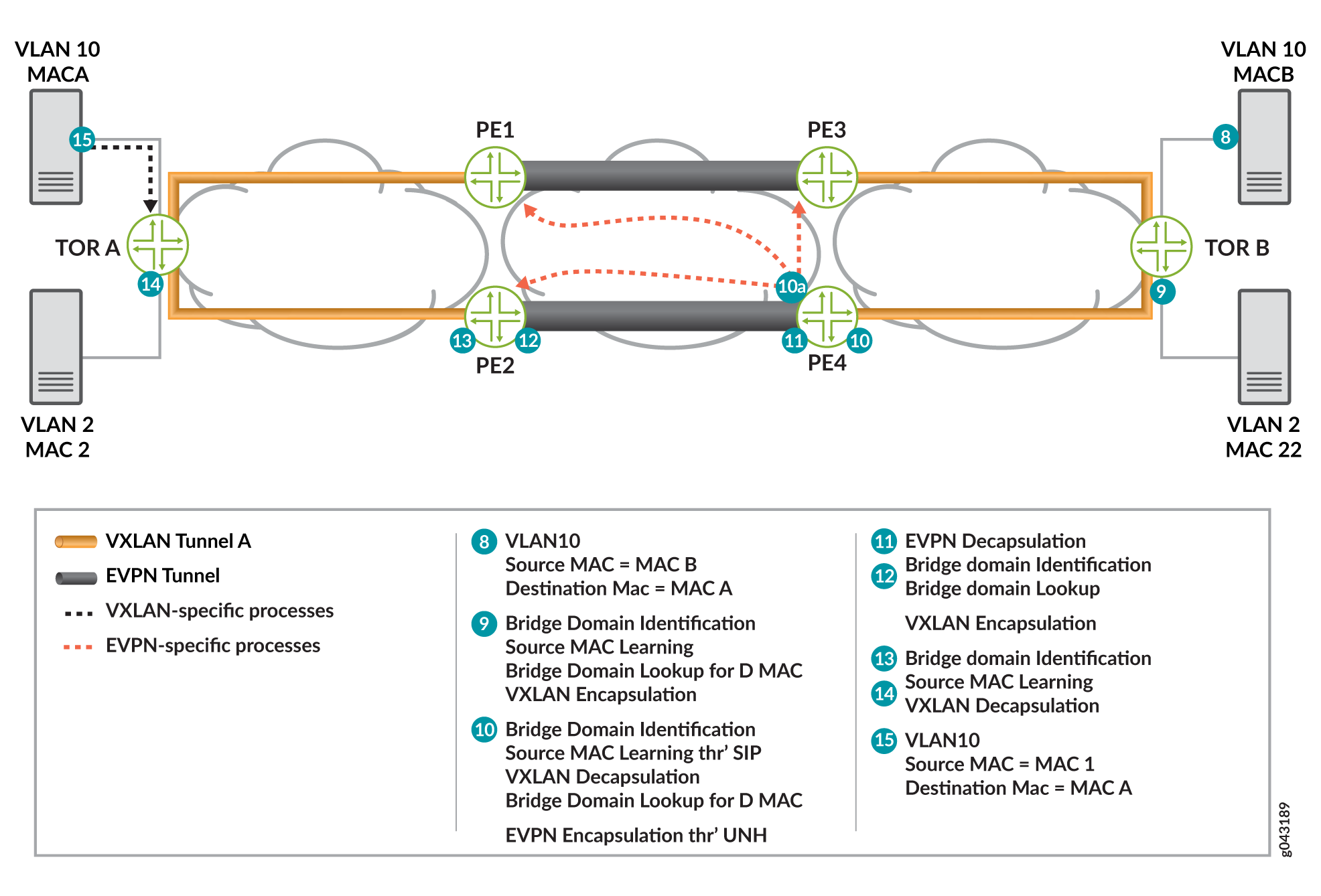
Assuming that both data and control plane MAC learning has already happened, the VXLAN to EVPN unicast traffic (ARP reply) from Server B is handled as follows:
-
8—Server B generates an ARP reply.
The contents of the ARP packets are as follows:
-
VLAN ID = VLAN 10
-
Source MAC = MACB (Server B interface MAC)
-
Destination MAC = MACA
-
Source IP address = IP address of Server B or VM IP address
-
Destination IP address = IP address of Server A
The ARP packet is forwarded to switch TOR B.
-
-
9—After receiving the frame, switch TOR B classifies the incoming frame. The frame is classified in an IFL on the received interface. Based on the IFL family, the bridge domain associated with IFL is identified. On the given bridge domain, TOR B learns the source MAC address. Once TOR B completes the bridge domain destination MAC (MACA) look up, this look up provides the VXLAN unicast next hop. This next hop contains all the information needed to form the VXLAN header.
The content of the next hop that is required to form the packet is as follows:
-
Source MAC Address = MAC Address of source IP address interface
-
Destination MAC address = MAC address of the next hop
-
Source IP address = 11.10.10.2
-
Destination IP Address = 11.10.10.1 (as a result of the MAC learning process)
-
Source UDP port = Calculated based on the hash on the incoming frame header
-
Destination UDP port = 4789 (well known port for the VXLAN tunnel)
Note:An earlier version of the VXLAN draft used 8472 as the UDP port.
-
-
10— Router PE receives the VXLAN encapsulated frame4. PE4 identifies the frame by completing the lookup using the destination IP address and the destination UDP port. This lookup results in the VXLAN decapsulation. The decapsulation next hop also stores the outer source IP address.
The next lookup is done based on the VNI ID 1000. This lookup results into the bride domain table.
-
10A—Router PE completes the source MAC to source IP address learning and L2ALD receives the MAC learning notification. This MAC is sent to RPD for distribution to other PE routers through BGP-EVPN MAC advertisement route. The BGP control plane distributes this MAC reachability information to all other PE routers.
The destination MAC (MAC1) lookup is done in the bridge domain MAC address table. This lookup results into a unicast next hop (EVPN NH).
-
11—The EVPN unicast next hop is executed. This next hop contains an unicast MPLS service label. This label is distributed through the MP-BGP control plane. The downstream peer allocates this MPLS service label. Allocation of this label can be per PE (PE, VLAN) or per MAC address basis. Based on the information in the next hop, the MPLS packet is formed and forwarded on the MPLS network.
-
12—Router PE2 receives the frame. The frame is identified as an MPLS packet. An MPLS label lookup is done in the MPLS.0 table. This lookup results in the table next hop and in the bridge domain table.
The destination MAC (MAC1) lookup is done in the bridge domain MAC table. This lookup results in a VXLAN unicast next hop.
-
13—The VXLAN unicast next hop contains all the information for building the VXLAN encapsulated header. The VXLAN header is imposed on the packet.
The contents of the VXLAN encapsulation next hop header are as follows:
-
Source MAC Address = MAC Address of source IP address interface
-
Destination MAC address = MAC address of the next hop
-
Source IP address = 10.10.10.2
-
Destination IP Address = 10.10.10.1 (as a result of the MAC learning process)
-
Source UDP port = Calculated based on the hash on the incoming frame header
-
Destination UDP port = 4789 (well known port for the VXLAN tunnel)
-
-
14—The VXLAN encapsulated frame is received by switch TOR A. TOR A identifies the frame by doing the lookup using the destination IP address and the destination UDP port. This lookup results in the VXLAN decapsulation. The de-encapsulated next hop also stores the outer source IP address.
The next lookup is done based on the VNI ID 1000. This lookup results into the bride domain table. TOR A completes the source MAC (MAC2) to source IP address (10.10.10.2) learning. TOR A looks up the destination MAC (MAC1) in the bridge domain MAC address table. This lookup results into a unicast next hop that has the information about the egress interface.
-
15—Server A receives the ARP reply, and Server A and Server B are ready to communicate.
Implementation Overview of VXLAN-EVPN Integration for DCI
The following sections provide use case scenarios for VXLAN-EVPN integration for DCI.
- VNI Base Service Use Case
- VNI Aware Service Use Case
- VXLAN-VLAN Interworking Use Case
- Inter VXLAN Routing Use Case
- Redundancy Use Case
VNI Base Service Use Case
In the case of the VNI base service, there is one-to-one mapping between a VNI and an EVI. In this case, there is no need to carry the VNI in the MAC advertisement route because the bridge domain ID can be derived from the route-target (RT) associated with this route. The MPLS label allocation is done per EVI basis.
Figure 7 provides an overview for VNI base use case scenarios. The VNI base service is used most commonly for achieving the VNI translation and VNI to VLAN interworking.
VNI Aware Service Use Case
In the case of VNI aware bundle mode, there are multiple VNIs that can be mapped to the same EVI. The Ethernet tag ID must be set to the VNI ID in the BGP routes advertisements. The MPLS label allocation in this use case should be done per EVI, VNI basis so that the VXLAN can be terminated at the ingress PE router and recreated at the egress PE router.
Figure 8 provides details about the VNI aware service used case.
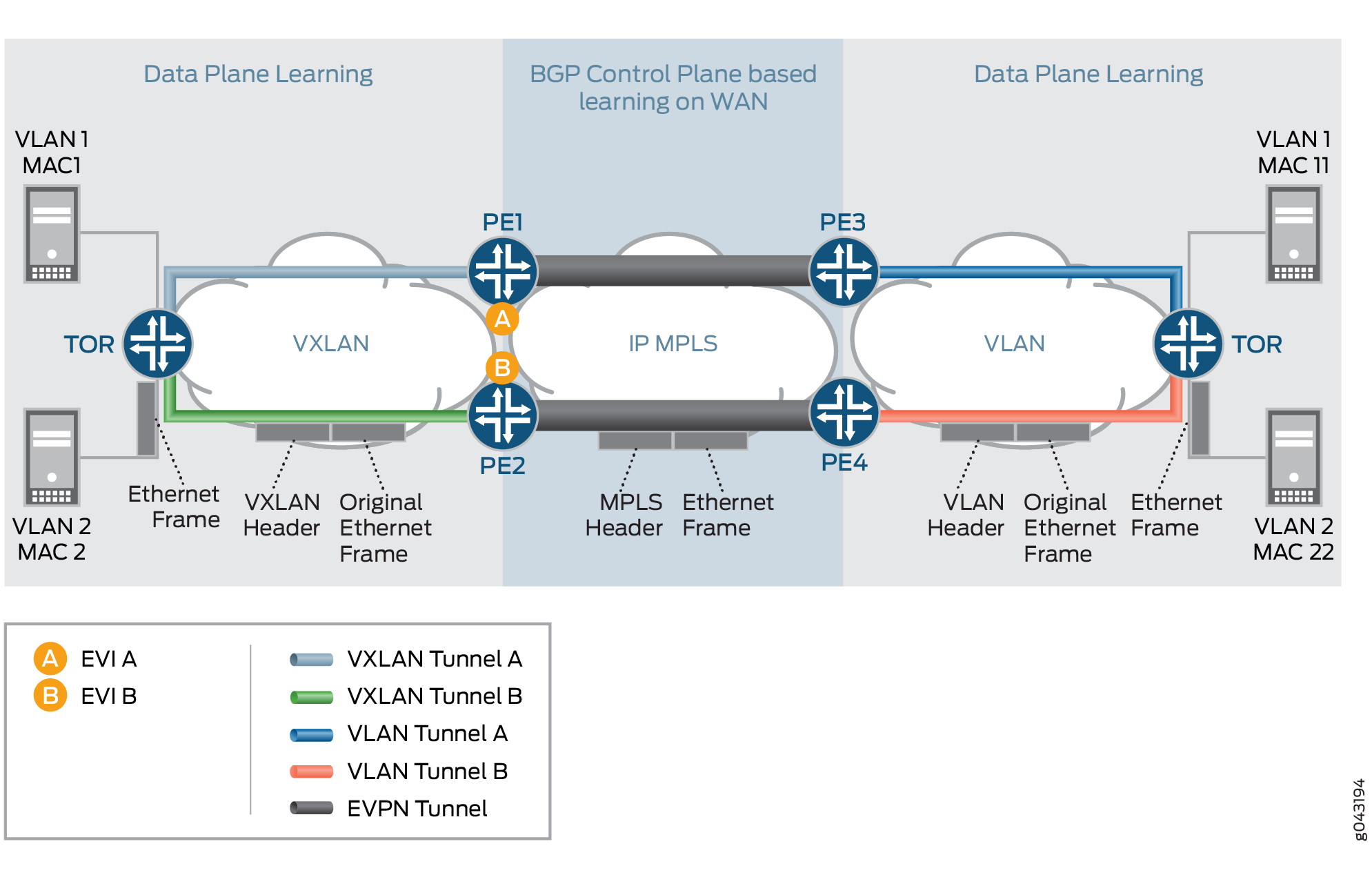
VXLAN-VLAN Interworking Use Case
This use case scenario is required for heterogeneous datacenter sites. In this scenario, the new data center site is a VXLAN-based datacenter site, and the old datacenter sites are based on VLAN. In this scenario, there is a need to have VXLAN interworking with VLAN over EVPN.
Figure 9 provides the detail packet walkthrough for the VXLAN-VLAN interworking use case scenario. There is a need to do the VLAN to VXLAN interworking and vice-versa from the control plane BGP route updates perspective. The label allocation needs to be done on a per EVI-basis.
Inter VXLAN Routing Use Case
In this use case, a VM or host in one subnet (VNI-A) wants to send traffic to a VM or host in a different subnet (VNI-B). In order to provide this communication, the inter VXLAN routing should be supported.
Figure 10 provides the use case scenarios for the inter VXLAN routing use case.
Redundancy Use Case
The two types of redundancy use case scenarios include Active-Standby and Active-Active.
Active-Standby Redundancy Use Case
In this use case scenario, the TOR switch (VXLAN originating GW), or the VXLAN network originating the VXLAN tunnel, is dual homed to two PE devices for active-standby redundancy. If the active link or node fails, a backup path takes over.
Figure 11 provides details of the active-standby redundancy use case scenario.
Active-Active Redundancy Use Case
When interconnecting EVPN VXLAN in a data center to EVPN-VXLAN in a WAN using a gateway model on QFX series platforms, you can configure Active-Active redundancy mode on multihomed customer edge devices to allow Layer 2 unicast traffic to be load-balanced across all the multihomed links on and toward the CE device.
Setting the interconnect-multihoming-peer-gateway CLI command is required for
MAC-VRF and VTEP-Scaling configurations. Note that in some cases, EVPN-VXLAN is supported only
in VTEP Scaling mode, where a single VTEP is created for a given peer device that may have
multiple routing instances. In this case, it is only possible to have a peer device be
represented as a WAN peer (WAN VTEP) or a DC VTEP (a normal VTEP).
For Active-Active redundancy, additional configurations are required in the “interconnect”
stanza to enable DCI interconnection. For a default switch (switch-options)
configuration, be sure to set the DCI under global protocols evpn.
Protocols EVPN Example:
evpn-vxlan-dc1
        vtep-source-interface lo0.0;
        instance-type mac-vrf;
        route-distinguisher 101:1;          //DC-RD
        vrf-target target:1:1;              //DC-RT
        protocols {
            evpn {
                encapsulation vxlan;
                extended-vni-list all;
        interconnect {
            vrf-target  target:2:2; // WAN RT
            vrf-import <>
            route-distinguisher 101:2;// WAN RD
            interconnected-vni-list all;
 		    esi {
 		        00:00:01:02:03:04:05:06:07:08;
 			    all-active;
             }
        }
            }
        }
        vlans  {
            bd1 {
                vlan-id 51;
                l3-interface irb.0;
                vxlan {
                    vni 51;
                    translation-vni <>
                }
            }
        }
    }


global
 protocols {
      evpn {
 	 	interconnect-multihoming-peer-gateways <GW>
       }
  }
Note: interconnect-multihoming-peer-gateways should be configured to contain
a list of all DCI peers on the same DC.
The list can contain up to 64 peer gateway entries. Be sure to configure under the
global protocol evpn stanza and not under any mac-vrf setting.
Example: Active-Active Multihoming provides details for active-active redundancy.
Supported and Unsupported Features for VXLAN DCI Using EVPN
Junos OS supports the following features for VXLAN DCI using EVPN:
-
One-to-one mapping of VXLAN tunnel and an EVPN instance. In other words, one-to-one mapping between a VNI and an EVI.
-
Many-to-one mapping of VXLAN tunnels over one EVPN instance, where multiple VNIs can be mapped to the same EVI.
-
VNI Translation.
Note:VNI translation is supported by normalizing a VXLAN tag into a VLAN.
-
VXLAN-to-VLAN interworking.
-
Inter-VXLAN routing.
-
Single active redundancy.
-
Active-active redundancy in the PIM BIDIR mode.
-
VXLAN tunnel traffic protection using IPSec.
-
Graceful Routing Engine switchover.
-
ISSU.
Junos OS does not support the following functionality for VXLAN DCI using EVPN:
-
VXLAN uses IANA assigned UDP port 4789. Packets destined to the UDP port 4789 are processed only when the VXLAN configuration is enabled. The VXLAN packets are de-encapsulated by the forwarding plane and an inner Layer 2 packet is processed. MAC learnt packets are generated for the control plane processing for newly learnt MAC entries. These entries are throttled using existing infrastructure for MAC learning. VXLAN generates addition learn messages for the remote endpoints. These messages are also throttled using the existing infrastructure for denial of service detection.
-
Packets received on the VXLAN tunnel are processed only if the VXLAN identifier in the packet is a known entity to the device. Unknown entities are discarded by the forwarding plane.
-
Using configurable firewall filters can be discarded before it reaches the VXLAN processing module in the forwarding plane of the MX series routers.
-
Logical systems.
Change History Table
Feature support is determined by the platform and release you are using. Use Feature Explorer to determine if a feature is supported on your platform.