Example: Configuring PBB with Single-Homed EVPN
This example shows how to integrate provider backbone bridging (PBB) with Ethernet VPN (EVPN). With this integration, the control plane operations in the core are simplified, providing faster convergence and scalability enhancements than regular EVPN. The PBB-EVPN applications include Data Center Interconnect (DCI) and carrier Ethernet E-LAN services.
Requirements
This example uses the following hardware and software components:
Three provider edge (PE) devices each connected to single-homed customer sites.
Four customer edge (CE) devices that are single-homed to the PE devices.
Junos OS Release 17.2R1 or later running on all the PE routers.
Before you begin:
Configure the device interfaces.
Configure an IGP, such as OSPF, on all the PE devices.
Establish an internal BGP session between the PE devices.
Enable RSVP on the PE devices.
Configure MPLS and label-switched paths (LSPs) between the PE devices.
Overview and Topology
With the introduction of the Integrating PBB with EVPN feature, PBB became integrated with Ethernet VPN (EVPN) to enable significant reduction in the control plane learning across the core, allowing a huge number of Layer 2 services, such as data center connectivity, to transit the network in a simplified manner. See the Integrating PBB with EVPN entry in Feature Explorer for platform and software release support for the Integrating PBB with EVPN feature.
In a PBB-EVPN network, the backbone core bridge (BCB) device in the PBB core is replaced with MPLS, while retaining the service scaling properties of the PBB backbone edge bridge (BEB). The B-component (provider routing instance) is signalled using EVPN BGP signaling and encapsulated inside MPLS using provider edge (PE) and provider (P) devices. Thus, PBB-EVPN combines the vast scaling property of PBB with the simplicity of a traditional basic MPLS core network, resulting in significant reduction in the amount of network-wide state information, as opposed to regular PBB.
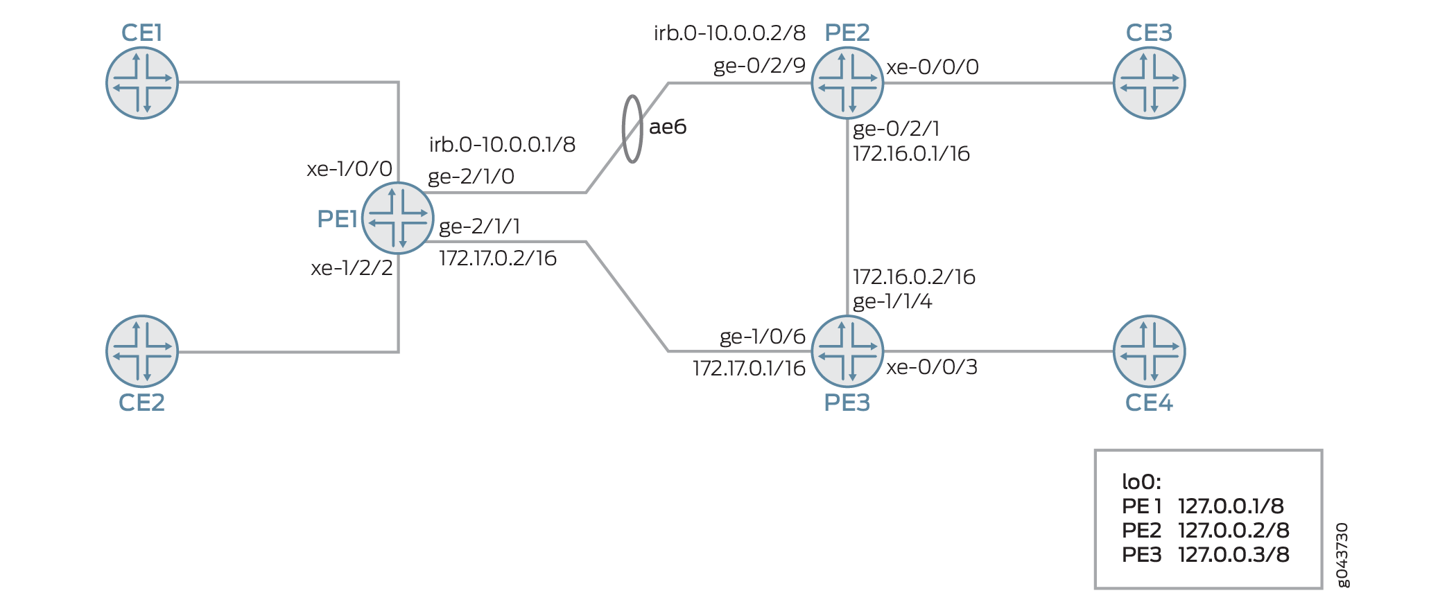
In Figure 1, PBB is integrated with EVPN, where the CE devices are single-homed to Devices PE1, PE2, and PE3.
Configuration
CLI Quick Configuration
To quickly configure this example, copy the following commands, paste them into a text file, remove any line breaks, change any details necessary to match your network configuration, copy and paste the commands into the CLI at the [edit] hierarchy level, and then enter commit from configuration mode.
PE1
set chassis aggregated-devices ethernet device-count 16

               set chassis network-services enhanced-ip

               set interfaces xe-1/0/0 flexible-vlan-tagging

               set interfaces xe-1/0/0 encapsulation flexible-ethernet-services

               set interfaces xe-1/0/0 unit 0 encapsulation vlan-bridge

               set interfaces xe-1/0/0 unit 0 vlan-id 10

               set interfaces xe-1/0/0 unit 1 encapsulation vlan-bridge

               set interfaces xe-1/0/0 unit 1 vlan-id 20

               set interfaces xe-1/2/2 flexible-vlan-tagging

               set interfaces xe-1/2/2 encapsulation flexible-ethernet-services

               set interfaces xe-1/2/2 unit 0 encapsulation vlan-bridge

               set interfaces xe-1/2/2 unit 0 vlan-id 10

               set interfaces xe-1/2/2 unit 0 family bridge filter input BRI

               set interfaces xe-1/2/2 unit 1 encapsulation vlan-bridge

               set interfaces xe-1/2/2 unit 1 vlan-id 20

               set interfaces xe-1/2/2 unit 2 encapsulation vlan-bridge

               set interfaces xe-1/2/2 unit 2 vlan-id 11

               set interfaces xe-1/2/2 unit 2 family bridge

               set interfaces xe-1/2/2 unit 3 encapsulation vlan-bridge

               set interfaces xe-1/2/2 unit 3 vlan-id 21

               set interfaces xe-1/2/2 unit 3 family bridge

               set interfaces ge-2/1/0 gigether-options 802.3ad ae6

               set interfaces ge-2/1/1 unit 0 family inet address 10.0.0.1/8

               set interfaces ge-2/1/1 unit 0 family iso

               set interfaces ge-2/1/1 unit 0 family mpls

               set interfaces ae6 encapsulation ethernet-bridge

               set interfaces ae6 unit 0 family bridge

               set interfaces cbp0 unit 0 family bridge interface-mode trunk

               set interfaces cbp0 unit 0 family bridge bridge-domain-type bvlan

               set interfaces cbp0 unit 0 family bridge isid-list all

               set interfaces cbp0 unit 1 family bridge interface-mode trunk

               set interfaces cbp0 unit 1 family bridge bridge-domain-type bvlan

               set interfaces cbp0 unit 1 family bridge isid-list all

               set interfaces irb unit 0 family inet address 10.0.0.1/8

               set interfaces irb unit 0 family iso

               set interfaces irb unit 0 family mpls

               set interfaces lo0 unit 0 family inet address 127.0.0.1/8 primary

               set interfaces pip0 unit 0 family bridge interface-mode trunk

               set interfaces pip0 unit 0 family bridge bridge-domain-type svlan

               set interfaces pip0 unit 0 family bridge isid-list all-service-groups

               set interfaces pip0 unit 1 family bridge interface-mode trunk

               set interfaces pip0 unit 1 family bridge bridge-domain-type svlan

               set interfaces pip0 unit 1 family bridge isid-list all-service-groups

               set routing-options router-id 127.0.0.1

               set routing-options autonomous-system 65221

               set protocols rsvp interface all

               set protocols rsvp interface fxp0.0 disable

               set protocols mpls label-switched-path PE1toPE2 from 127.0.0.1

               set protocols mpls label-switched-path PE1toPE2 to 127.0.0.2

               set protocols mpls label-switched-path PE1toPE3 from 127.0.0.1

               set protocols mpls label-switched-path PE1toPE3 to 127.0.0.3

               set protocols mpls interface all

               set protocols mpls interface fxp0.0 disable

               set protocols bgp group ibgp type internal

               set protocols bgp group ibgp local-address 127.0.0.1

               set protocols bgp group ibgp family evpn signaling

               set protocols bgp group ibgp neighbor 127.0.0.2

               set protocols bgp group ibgp neighbor 127.0.0.3

               set protocols ospf traffic-engineering

               set protocols ospf area 0.0.0.0 interface all

               set protocols ospf area 0.0.0.0 interface fxp0.0 disable

               set routing-instances pbbn1 instance-type virtual-switch

               set routing-instances pbbn1 interface cbp0.0

               set routing-instances pbbn1 route-distinguisher 127.0.0.1:100

               set routing-instances pbbn1 vrf-target target:100:100

               set routing-instances pbbn1 protocols evpn pbb-evpn-core

               set routing-instances pbbn1 protocols evpn extended-isid-list 1000

               set routing-instances pbbn1 protocols evpn extended-isid-list 2000

               set routing-instances pbbn1 bridge-domains bda vlan-id 100

               set routing-instances pbbn1 bridge-domains bda isid-list 1000

               set routing-instances pbbn1 bridge-domains bda vlan-id-scope-local

               set routing-instances pbbn1 bridge-domains bdb vlan-id 200

               set routing-instances pbbn1 bridge-domains bdb isid-list 2000

               set routing-instances pbbn1 bridge-domains bdb vlan-id-scope-local

               set routing-instances pbn1 instance-type virtual-switch

               set routing-instances pbn1 interface pip0.0

               set routing-instances pbn1 bridge-domains bda domain-type bridge

               set routing-instances pbn1 bridge-domains bda vlan-id 10

               set routing-instances pbn1 bridge-domains bda interface xe-1/2/2.0

               set routing-instances pbn1 bridge-domains bda interface xe-1/0/0.0

               set routing-instances pbn1 bridge-domains bdb domain-type bridge

               set routing-instances pbn1 bridge-domains bdb vlan-id 20

               set routing-instances pbn1 bridge-domains bdb interface xe-1/2/2.1

               set routing-instances pbn1 bridge-domains bdb interface xe-1/0/0.1

               set routing-instances pbn1 bridge-domains bdc domain-type bridge

               set routing-instances pbn1 bridge-domains bdc vlan-id 11

               set routing-instances pbn1 bridge-domains bdc interface xe-1/2/2.2

               set routing-instances pbn1 bridge-domains bdd domain-type bridge

               set routing-instances pbn1 bridge-domains bdd vlan-id 21

               set routing-instances pbn1 bridge-domains bdd interface xe-1/2/2.3

               set routing-instances pbn1 pbb-options peer-instance pbbn1

               set routing-instances pbn1 service-groups sga service-type elan

               set routing-instances pbn1 service-groups sga pbb-service-options isid 1000 vlan-id-list 10

               set routing-instances pbn1 service-groups sga pbb-service-options isid 1000 vlan-id-list 11

               set routing-instances pbn1 service-groups sga pbb-service-options source-bmac 00:50:50:50:50:50

               set routing-instances pbn1 service-groups sgb service-type elan

               set routing-instances pbn1 service-groups sgb pbb-service-options isid 2000 vlan-id-list 20

               set routing-instances pbn1 service-groups sgb pbb-service-options isid 2000 vlan-id-list 21

               set bridge-domains bd vlan-id none

               set bridge-domains bd interface ae6.0

               set bridge-domains bd routing-interface irb.0
PE2
               set chassis aggregated-devices ethernet device-count 3

               set chassis network-services enhanced-ip

               set interfaces xe-0/0/0 flexible-vlan-tagging

               set interfaces xe-0/0/0 encapsulation flexible-ethernet-services

               set interfaces xe-0/0/0 unit 0 encapsulation vlan-bridge

               set interfaces xe-0/0/0 unit 0 vlan-id 10

               set interfaces xe-0/0/0 unit 1 encapsulation vlan-bridge

               set interfaces xe-0/0/0 unit 1 vlan-id 20

               set interfaces xe-0/0/0 unit 2 encapsulation vlan-bridge

               set interfaces xe-0/0/0 unit 2 vlan-id 11

               set interfaces xe-0/0/0 unit 2 family bridge

               set interfaces xe-0/0/0 unit 3 encapsulation vlan-bridge

               set interfaces xe-0/0/0 unit 3 vlan-id 21

               set interfaces xe-0/0/0 unit 3 family bridge

               set interfaces ge-0/2/1 unit 0 family inet address 172.16.0.1/16

               set interfaces ge-0/2/1 unit 0 family mpls

               set interfaces ge-0/2/9 gigether-options 802.3ad ae6

               set interfaces ae6 encapsulation ethernet-bridge

               set interfaces ae6 unit 0 family bridge

               set interfaces cbp0 unit 0 family bridge interface-mode trunk

               set interfaces cbp0 unit 0 family bridge bridge-domain-type bvlan

               set interfaces cbp0 unit 0 family bridge isid-list all

               set interfaces cbp0 unit 1 family bridge interface-mode trunk

               set interfaces cbp0 unit 1 family bridge bridge-domain-type bvlan

               set interfaces cbp0 unit 1 family bridge isid-list all

               set interfaces irb unit 0 family inet address 10.0.0.2/8

               set interfaces irb unit 0 family mpls

               set interfaces lo0 unit 0 family inet address 127.0.0.2/8 primary

               set interfaces pip0 unit 0 family bridge interface-mode trunk

               set interfaces pip0 unit 0 family bridge bridge-domain-type svlan

               set interfaces pip0 unit 0 family bridge isid-list all-service-groups

               set interfaces pip0 unit 1 family bridge interface-mode trunk

               set interfaces pip0 unit 1 family bridge bridge-domain-type svlan

               set interfaces pip0 unit 1 family bridge isid-list all-service-groups

               set routing-options router-id 127.0.0.2

               set routing-options autonomous-system 65221

               set protocols rsvp interface all

               set protocols rsvp interface fxp0.0 disable

               set protocols mpls label-switched-path PE2toPE1 from 127.0.0.2

               set protocols mpls label-switched-path PE2toPE1 to 127.0.0.1

               set protocols mpls label-switched-path PE2toPE3 from 127.0.0.2

               set protocols mpls label-switched-path PE2toPE3 to 127.0.0.3

               set protocols mpls interface all

               set protocols mpls interface fxp0.0 disable

               set protocols bgp group ibgp type internal

               set protocols bgp group ibgp local-address 127.0.0.2

               set protocols bgp group ibgp family evpn signaling

               set protocols bgp group ibgp neighbor 127.0.0.1

               set protocols bgp group ibgp neighbor 127.0.0.3

               set protocols ospf traffic-engineering

               set protocols ospf area 0.0.0.0 interface all

               set protocols ospf area 0.0.0.0 interface fxp0.0 disable

               set routing-instances pbbn1 instance-type virtual-switch

               set routing-instances pbbn1 interface cbp0.0

               set routing-instances pbbn1 route-distinguisher 127.0.0.2:100

               set routing-instances pbbn1 vrf-target target:100:100

               set routing-instances pbbn1 protocols evpn pbb-evpn-core

               set routing-instances pbbn1 protocols evpn extended-isid-list 1000

               set routing-instances pbbn1 protocols evpn extended-isid-list 2000

               set routing-instances pbbn1 bridge-domains bda vlan-id 100

               set routing-instances pbbn1 bridge-domains bda isid-list 1000

               set routing-instances pbbn1 bridge-domains bda vlan-id-scope-local

               set routing-instances pbbn1 bridge-domains bdb vlan-id 200

               set routing-instances pbbn1 bridge-domains bdb isid-list 2000

               set routing-instances pbbn1 bridge-domains bdb vlan-id-scope-local

               set routing-instances pbn1 instance-type virtual-switch

               set routing-instances pbn1 interface pip0.0

               set routing-instances pbn1 bridge-domains bda domain-type bridge

               set routing-instances pbn1 bridge-domains bda vlan-id 10

               set routing-instances pbn1 bridge-domains bda interface xe-0/0/0.0

               set routing-instances pbn1 bridge-domains bdb domain-type bridge

               set routing-instances pbn1 bridge-domains bdb vlan-id 20

               set routing-instances pbn1 bridge-domains bdb interface xe-0/0/0.1

               set routing-instances pbn1 bridge-domains bdc domain-type bridge

               set routing-instances pbn1 bridge-domains bdc vlan-id 11

               set routing-instances pbn1 bridge-domains bdc interface xe-0/0/0.2

               set routing-instances pbn1 bridge-domains bdd domain-type bridge

               set routing-instances pbn1 bridge-domains bdd vlan-id 21

               set routing-instances pbn1 bridge-domains bdd interface xe-0/0/0.3

               set routing-instances pbn1 pbb-options peer-instance pbbn1

               set routing-instances pbn1 service-groups sga service-type elan

               set routing-instances pbn1 service-groups sga pbb-service-options isid 1000 vlan-id-list 10

               set routing-instances pbn1 service-groups sga pbb-service-options isid 1000 vlan-id-list 11

               set routing-instances pbn1 service-groups sga pbb-service-options source-bmac 00:51:51:51:51:51

               set routing-instances pbn1 service-groups sgb service-type elan

               set routing-instances pbn1 service-groups sgb pbb-service-options isid 2000 vlan-id-list 20

               set routing-instances pbn1 service-groups sgb pbb-service-options isid 2000 vlan-id-list 21

               set bridge-domains bd vlan-id none

               set bridge-domains bd interface ae6.0

               set bridge-domains bd routing-interface irb.0
PE3
               set chassis aggregated-devices ethernet device-count 16

               set chassis network-services enhanced-ip

               set interfaces xe-0/0/3 flexible-vlan-tagging

               set interfaces xe-0/0/3 encapsulation flexible-ethernet-services

               set interfaces xe-0/0/3 unit 0 encapsulation vlan-bridge

               set interfaces xe-0/0/3 unit 0 vlan-id 10

               set interfaces xe-0/0/3 unit 1 encapsulation vlan-bridge

               set interfaces xe-0/0/3 unit 1 vlan-id 20

               set interfaces xe-0/0/3 unit 2 encapsulation vlan-bridge

               set interfaces xe-0/0/3 unit 2 vlan-id 11

               set interfaces xe-0/0/3 unit 2 family bridge

               set interfaces xe-0/0/3 unit 3 encapsulation vlan-bridge

               set interfaces xe-0/0/3 unit 3 vlan-id 21

               set interfaces xe-0/0/3 unit 3 family bridge

               set interfaces ge-1/0/6 unit 0 family inet address 172.17.0.1/16

               set interfaces ge-1/0/6 unit 0 family mpls

               set interfaces ge-1/1/4 unit 0 family inet address 172.16.0.2/16

               set interfaces ge-1/1/4 unit 0 family mpls

               set interfaces cbp0 unit 0 family bridge interface-mode trunk

               set interfaces cbp0 unit 0 family bridge bridge-domain-type bvlan

               set interfaces cbp0 unit 0 family bridge isid-list all

               set interfaces cbp0 unit 1 family bridge interface-mode trunk

               set interfaces cbp0 unit 1 family bridge bridge-domain-type bvlan

               set interfaces cbp0 unit 1 family bridge isid-list all

               set interfaces lo0 unit 0 family inet address 127.0.0.3/8 primary

               set interfaces pip0 unit 0 family bridge interface-mode trunk

               set interfaces pip0 unit 0 family bridge bridge-domain-type svlan

               set interfaces pip0 unit 0 family bridge isid-list all-service-groups

               set interfaces pip0 unit 1 family bridge interface-mode trunk

               set interfaces pip0 unit 1 family bridge bridge-domain-type svlan

               set interfaces pip0 unit 1 family bridge isid-list all-service-groups

               set routing-options router-id 127.0.0.3

               set routing-options autonomous-system 65221

               set protocols rsvp interface all

               set protocols rsvp interface fxp0.0 disable

               set protocols mpls label-switched-path PE3toPE1 from 127.0.0.3

               set protocols mpls label-switched-path PE3toPE1 to 127.0.0.1

               set protocols mpls label-switched-path PE3toPE2 from 127.0.0.3

               set protocols mpls label-switched-path PE3toPE2 to 127.0.0.2

               set protocols mpls interface all

               set protocols mpls interface fxp0.0 disable

               set protocols bgp group ibgp type internal

               set protocols bgp group ibgp local-address 127.0.0.3

               set protocols bgp group ibgp family evpn signaling

               set protocols bgp group ibgp neighbor 127.0.0.1

               set protocols bgp group ibgp neighbor 127.0.0.2

               set protocols ospf traffic-engineering

               set protocols ospf area 0.0.0.0 interface all

               set protocols ospf area 0.0.0.0 interface fxp0.0 disable

               set routing-instances pbbn1 instance-type virtual-switch

               set routing-instances pbbn1 interface cbp0.0

               set routing-instances pbbn1 route-distinguisher 127.0.0.3:100

               set routing-instances pbbn1 vrf-target target:100:100

               set routing-instances pbbn1 protocols evpn pbb-evpn-core

               set routing-instances pbbn1 protocols evpn extended-isid-list 1000

               set routing-instances pbbn1 protocols evpn extended-isid-list 2000

               set routing-instances pbbn1 bridge-domains bda vlan-id 100

               set routing-instances pbbn1 bridge-domains bda isid-list 1000

               set routing-instances pbbn1 bridge-domains bda vlan-id-scope-local

               set routing-instances pbbn1 bridge-domains bdb vlan-id 200

               set routing-instances pbbn1 bridge-domains bdb isid-list 2000

               set routing-instances pbbn1 bridge-domains bdb vlan-id-scope-local

               set routing-instances pbn1 instance-type virtual-switch

               set routing-instances pbn1 interface pip0.0

               set routing-instances pbn1 bridge-domains bda domain-type bridge

               set routing-instances pbn1 bridge-domains bda vlan-id 10

               set routing-instances pbn1 bridge-domains bda interface xe-0/0/3.0

               set routing-instances pbn1 bridge-domains bdb domain-type bridge

               set routing-instances pbn1 bridge-domains bdb vlan-id 20

               set routing-instances pbn1 bridge-domains bdb interface xe-0/0/3.1

               set routing-instances pbn1 bridge-domains bdc domain-type bridge

               set routing-instances pbn1 bridge-domains bdc vlan-id 11

               set routing-instances pbn1 bridge-domains bdc interface xe-0/0/3.2

               set routing-instances pbn1 bridge-domains bdd domain-type bridge

               set routing-instances pbn1 bridge-domains bdd vlan-id 21

               set routing-instances pbn1 bridge-domains bdd interface xe-0/0/3.3

               set routing-instances pbn1 pbb-options peer-instance pbbn1

               set routing-instances pbn1 service-groups sga service-type elan

               set routing-instances pbn1 service-groups sga pbb-service-options isid 1000 vlan-id-list 10

               set routing-instances pbn1 service-groups sga pbb-service-options isid 1000 vlan-id-list 11

               set routing-instances pbn1 service-groups sga pbb-service-options source-bmac 00:52:52:52:52:52

               set routing-instances pbn1 service-groups sgb service-type elan

               set routing-instances pbn1 service-groups sgb pbb-service-options isid 2000 vlan-id-list 20

               set routing-instances pbn1 service-groups sgb pbb-service-options isid 2000 vlan-id-list 21
Procedure
Step-by-Step Procedure
The following example requires that you navigate various levels in the configuration hierarchy. For information about navigating the CLI, see Using the CLI Editor in Configuration Mode in the CLI User Guide.
To configure Device PE1:
Set the number of aggregated Ethernet interfaces on Device PE1.
[edit chassis]
user@PE1# set aggregated-devices ethernet device-count 16
Set Device PE1’s network services to enhanced Internet Protocol and use enhanced mode capabilities.
[edit chassis]
user@PE1# set chassis network-services enhanced-ip
Configure the CE-facing interfaces of Device PE1.
[edit interfaces]
user@PE1# set xe-1/0/0 flexible-vlan-tagging
user@PE1# set xe-1/0/0 encapsulation flexible-ethernet-services
user@PE1# set xe-1/0/0 unit 0 encapsulation vlan-bridge
user@PE1# set xe-1/0/0 unit 0 vlan-id 10
user@PE1# set xe-1/0/0 unit 1 encapsulation vlan-bridge
user@PE1# set xe-1/0/0 unit 1 vlan-id 20
user@PE1# set xe-1/2/2 flexible-vlan-tagging
user@PE1# set xe-1/2/2 encapsulation flexible-ethernet-services
user@PE1# set xe-1/2/2 unit 0 encapsulation vlan-bridge
user@PE1# set xe-1/2/2 unit 0 vlan-id 10
user@PE1# set xe-1/2/2 unit 0 family bridge filter input BRI
user@PE1# set xe-1/2/2 unit 1 encapsulation vlan-bridge
user@PE1# set xe-1/2/2 unit 1 vlan-id 20
user@PE1# set xe-1/2/2 unit 2 encapsulation vlan-bridge
user@PE1# set xe-1/2/2 unit 2 vlan-id 11
user@PE1# set xe-1/2/2 unit 2 family bridge
user@PE1# set xe-1/2/2 unit 3 encapsulation vlan-bridge
user@PE1# set xe-1/2/2 unit 3 vlan-id 21
user@PE1# set xe-1/2/2 unit 3 family bridge
Configure the interfaces connecting Device PE1 with the other PE devices.
[edit interfaces]
user@PE1# set ge-2/1/0 gigether-options 802.3ad ae6
user@PE1# set ge-2/1/1 unit 0 family inet address 10.0.0.1/8
user@PE1# set ge-2/1/1 unit 0 family iso
user@PE1# set ge-2/1/1 unit 0 family mpls
Configure the aggregated Ethernet bundle ae6.
[edit interfaces]
user@PE1# set ae6 encapsulation ethernet-bridge
user@PE1# set ae6 unit 0 family bridge
Configure the loopback interface of Device PE1.
[edit interfaces]
user@PE1# set interfaces lo0 unit 0 family inet address 127.0.0.1/8 primary
Configure the integrated routing and bridging (IRB) interfaces for Device PE1.
[edit interfaces]
user@PE1# set interfaces irb unit 0 family inet address 10.0.0.1/8
user@PE1# set interfaces irb unit 0 family iso
user@PE1# set interfaces irb unit 0 family mpls
Configure the customer backbone port (CBP) interfaces on Device PE1.
[edit interfaces]
user@PE1# set cbp0 unit 0 family bridge interface-mode trunk
user@PE1# set cbp0 unit 0 family bridge bridge-domain-type bvlan
user@PE1# set cbp0 unit 0 family bridge isid-list all
user@PE1# set cbp0 unit 1 family bridge interface-mode trunk
user@PE1# set cbp0 unit 1 family bridge bridge-domain-type bvlan
user@PE1# set cbp0 unit 1 family bridge isid-list all
Configure the Provider Instance Port (PIP) on Device PE1.
[edit interfaces]
user@PE1# set pip0 unit 0 family bridge interface-mode trunk
user@PE1# set pip0 unit 0 family bridge bridge-domain-type svlan
user@PE1# set pip0 unit 0 family bridge isid-list all-service-groups
user@PE1# set pip0 unit 1 family bridge interface-mode trunk
user@PE1# set pip0 unit 1 family bridge bridge-domain-type svlan
user@PE1# set pip0 unit 1 family bridge isid-list all-service-groups
Configure the router ID and autonomous system number for Device PE1.
[edit routing-options]
user@PE1# set router-id 127.0.0.1
user@PE1# set autonomous-system 65221
Configure RSVP on all the interfaces of Device PE1, excluding the management interface.
[edit protocols]
user@PE1# set rsvp interface all
user@PE1# set rsvp interface fxp0.0 disable
Configure MPLS on all the interfaces of Device PE1, excluding the management interface.
[edit protocols]
user@PE1# set mpls interface all
user@PE1# set mpls interface fxp0.0 disable
Configure LSPs from Device PE1 to all other PE devices.
[edit protocols]
user@PE1# set mpls label-switched-path PE1toPE2 from 127.0.0.1
user@PE1# set mpls label-switched-path PE1toPE2 to 127.0.0.2
user@PE1# set mpls label-switched-path PE1toPE3 from 127.0.0.1
user@PE1# set mpls label-switched-path PE1toPE3 to 127.0.0.3
Configure an internal BGP session under family EVPN from Device PE1 to all other PE devices.
[edit protocols]
user@PE1# set bgp group ibgp type internal
user@PE1# set bgp group ibgp local-address 127.0.0.1
user@PE1# set bgp group ibgp family evpn signaling
user@PE1# set bgp group ibgp neighbor 127.0.0.2
user@PE1# set bgp group ibgp neighbor 127.0.0.3
Configure OSPF on all the interfaces of Device of PE1, excluding the management interface.
[edit protocols]
user@PE1# set ospf traffic-engineering
user@PE1# set ospf area 0.0.0.0 interface all
user@PE1# set ospf area 0.0.0.0 interface fxp0.0 disable
Configure a customer routing instance (I-component) on Device PE1 with type virtual switch. Assign the CBP interface, route-distinguisher, and virtual routing and forwarding (VRF) target values to the PBBN routing instance.
[edit routing-instances]
user@PE1# set pbbn1 instance-type virtual-switch
user@PE1# set pbbn1 interface cbp0.0
user@PE1# set pbbn1 route-distinguisher 127.0.0.1:100
user@PE1# set pbbn1 vrf-target target:100:100
Configure PBB-EVPN integration from the customer routing instance. Assign the extended I-SID list and bridge domains to the routing instance.
[edit routing-instances]
user@PE1# set pbbn1 protocols evpn pbb-evpn-core
user@PE1# set pbbn1 protocols evpn extended-isid-list 1000
user@PE1# set pbbn1 protocols evpn extended-isid-list 2000
user@PE1# set pbbn1 bridge-domains bda vlan-id 100
user@PE1# set pbbn1 bridge-domains bda isid-list 1000
user@PE1# set pbbn1 bridge-domains bda vlan-id-scope-local
user@PE1# set pbbn1 bridge-domains bdb vlan-id 200
user@PE1# set pbbn1 bridge-domains bdb isid-list 2000
user@PE1# set pbbn1 bridge-domains bdb vlan-id-scope-local
Configure a provider routing instance on Device PE1 with type virtual switch. Assign the PBP interface and bridge domains to the routing instance.
[edit routing-instances]
user@PE1# set pbn1 instance-type virtual-switch
user@PE1# set pbn1 interface pip0.0
user@PE1# set pbn1 bridge-domains bda domain-type bridge
user@PE1# set pbn1 bridge-domains bda vlan-id 10
user@PE1# set pbn1 bridge-domains bda interface xe-1/2/2.0
user@PE1# set pbn1 bridge-domains bda interface xe-1/0/0.0
user@PE1# set pbn1 bridge-domains bdb domain-type bridge
user@PE1# set pbn1 bridge-domains bdb vlan-id 20
user@PE1# set pbn1 bridge-domains bdb interface xe-1/2/2.1
user@PE1# set pbn1 bridge-domains bdb interface xe-1/0/0.1
user@PE1# set pbn1 bridge-domains bdc domain-type bridge
user@PE1# set pbn1 bridge-domains bdc vlan-id 11
user@PE1# set pbn1 bridge-domains bdc interface xe-1/2/2.2
user@PE1# set pbn1 bridge-domains bdd domain-type bridge
user@PE1# set pbn1 bridge-domains bdd vlan-id 21
user@PE1# set pbn1 bridge-domains bdd interface xe-1/2/2.3
Configure the peer PBBN routing instance in the customer routing instance.
[edit routing-instances]
user@PE1# set pbn1 pbb-options peer-instance pbbn1
Configure the service groups to be supported in the customer routing instance.
[edit routing-instances]
user@PE1# set pbn1 service-groups sga service-type elan
user@PE1# set pbn1 service-groups sga pbb-service-options isid 1000 vlan-id-list 10
user@PE1# set pbn1 service-groups sga pbb-service-options isid 1000 vlan-id-list 11
user@PE1# set pbn1 service-groups sga pbb-service-options source-bmac 00:50:50:50:50:50
user@PE1# set pbn1 service-groups sgb service-type elan
user@PE1# set pbn1 service-groups sgb pbb-service-options isid 2000 vlan-id-list 20
user@PE1# set pbn1 service-groups sgb pbb-service-options isid 2000 vlan-id-list 21
Configure the bridge domains on Device PE1.
[edit bridge-domains]
user@PE1# set bd vlan-id none
user@PE1# set bd interface ae6.0
user@PE1# set bd routing-interface irb.0
Results
From configuration mode, confirm your configuration by entering the show chassis, show interfaces, show routing-options, show protocols, show routing-instances, and show bridge-domains commands. If the output does not display the intended configuration, repeat the instructions in this example to correct the configuration.
user@PE1# show chassis
aggregated-devices {
    ethernet {
        device-count 16;
    }
}
network-services enhanced-ip;
user@PE1# show interfaces
xe-1/0/0 {
    flexible-vlan-tagging;
    encapsulation flexible-ethernet-services;
    unit 0 {
        encapsulation vlan-bridge;
        vlan-id 10;
    }
    unit 1 {
        encapsulation vlan-bridge;
        vlan-id 20;
    }
}
xe-1/2/2 {
    flexible-vlan-tagging;
    encapsulation flexible-ethernet-services;
    unit 0 {
        encapsulation vlan-bridge;
        vlan-id 10;
        family bridge {
            filter {
                input BRI; ## reference 'BRI' not found
            }
        }
    }
    unit 1 {
        encapsulation vlan-bridge;
        vlan-id 20;
    }
    unit 2 {
        encapsulation vlan-bridge;
        vlan-id 11;
        family bridge;
    }
    unit 3 {
        encapsulation vlan-bridge;
        vlan-id 21;
        family bridge;
    }
}
ge-2/1/0 {
    gigether-options {
        802.3ad ae6;
    }
}
ge-2/1/1 {
    unit 0 {
        family inet {
            address 10.0.0.1/8;
        }
        family iso;
        family mpls;
    }
}
ae6 {
    encapsulation ethernet-bridge;
    unit 0 {
        family bridge;
    }
}
cbp0 {
    unit 0 {
        family bridge {
            interface-mode trunk;
            bridge-domain-type bvlan;
            isid-list all;
        }
    }
    unit 1 {
        family bridge {
            interface-mode trunk;
            bridge-domain-type bvlan;
            isid-list all;
        }
    }
}
irb {
    unit 0 {
        family inet {
            address 10.0.0.1/8;
        }
        family iso;
        family mpls;
    }
}
lo0 {
    unit 0 {
        family inet {
            address 127.0.0.1/8 {
                primary;
            }
        }
    }
}
pip0 {
    unit 0 {
        family bridge {
            interface-mode trunk;
            bridge-domain-type svlan;
            isid-list all-service-groups;
        }
    }
    unit 1 {
        family bridge {
            interface-mode trunk;
            bridge-domain-type svlan;
            isid-list all-service-groups;
        }
    }
}
user@PE1# show routing-options
router-id 127.0.0.1;
autonomous-system 65221;
user@PE1# show protocols
rsvp {
    interface all;
    interface fxp0.0 {
        disable;
    }
}
mpls {
    label-switched-path PE1toPE2 {
        from 127.0.0.1;
        to 127.0.0.2;
    }
    label-switched-path PE1toPE3 {
        from 127.0.0.1;
        to 127.0.0.3;
    }
    interface all;
    interface fxp0.0 {
        disable;
    }
}
bgp {
    group ibgp {
        type internal;
        local-address 127.0.0.1;
        family evpn {
            signaling;
        }
        neighbor 127.0.0.2;
        neighbor 127.0.0.3;
    }
}
ospf {
    traffic-engineering;
    area 0.0.0.0 {
        interface all;
        interface fxp0.0 {
            disable;
        }
    }
}
user@PE1# show routing-instances
pbbn1 {
    instance-type virtual-switch;
    interface cbp0.0;
    route-distinguisher 127.0.0.1:100;
    vrf-target target:100:100;
    protocols {
        evpn {
            pbb-evpn-core;
            extended-isid-list [ 1000 2000 ];
        }
    }
    bridge-domains {
        bda {
            vlan-id 100;
            isid-list 1000;
            vlan-id-scope-local;
        }
        bdb {
            vlan-id 200;
            isid-list 2000;
            vlan-id-scope-local;
        }
    }
}
pbn1 {
    instance-type virtual-switch;
    interface pip0.0;
    bridge-domains {
        bda {
            domain-type bridge;
            vlan-id 10;
            interface xe-1/2/2.0;
            interface xe-1/0/0.0;
        }
        bdb {
            domain-type bridge;
            vlan-id 20;
            interface xe-1/2/2.1;
            interface xe-1/0/0.1;
        }
        bdc {
            domain-type bridge;
            vlan-id 11;
            interface xe-1/2/2.2;
        }
        bdd {
            domain-type bridge;
            vlan-id 21;
            interface xe-1/2/2.3;
        }
    }
    pbb-options {
        peer-instance pbbn1;
    }
    service-groups {
        sga {
            service-type elan;
            pbb-service-options {
                isid 1000 vlan-id-list [ 10 11 ];
                source-bmac 00:50:50:50:50:50;
            }
        }
        sgb {
            service-type elan;
            pbb-service-options {
                isid 2000 vlan-id-list [ 20 21 ];
            }
        }
    }
}
user@PE1# show bridge-domains
bd {
    vlan-id none;
    interface ae6.0;
    routing-interface irb.0;
}
If you are done configuring the device, enter commit from configuration mode.
Verification
Confirm that the configuration is working properly.
- Verifying BGP Peering Status
- Verifying MPLS LSPs
- Verifying the EVPN Routing Instance
- Verifying Routing Table Entries of the EVPN Routing Instance
- Verifying the EVPN Database
- Verifying the MAC Table Entries
- Verifying the inet.3 Routing Table Entries
Verifying BGP Peering Status
Purpose
Verify that the BGP session is established between the PE devices.
Action
From operational mode, run the show bgp summary command.
user@PE1> show bgp summary
Groups: 1 Peers: 2 Down peers: 0
Table          Tot Paths  Act Paths Suppressed    History Damp State    Pending
bgp.evpn.0
                       8          8          0          0          0          0
Peer                     AS      InPkt     OutPkt    OutQ   Flaps Last Up/Dwn State|#Active/Received/Accepted/Damped...
127.0.0.2         65221          9          7       0       0        2:09 Establ
  bgp.evpn.0: 4/4/4/0
  pbbn1.evpn.0: 4/4/4/0
  __default_evpn__.evpn.0: 0/0/0/0
127.0.0.3         65221          7          7       0       0        1:25 Establ
  bgp.evpn.0: 4/4/4/0
  pbbn1.evpn.0: 4/4/4/0
__default_evpn__.evpn.0: 0/0/0/0
Meaning
A BGP session is established between the PE devices.
Verifying MPLS LSPs
Purpose
Verify the MPLS LSP status on Device PE1.
Action
From operational mode, run the show mpls lsp command.
user@PE1> show mpls lsp
Ingress LSP: 2 sessions
To              From            State Rt P     ActivePath       LSPname
127.0.0.2   127.0.0.1   Up     0 *                      PE1toPE2
127.0.0.3   127.0.0.1   Up     0 *                      PE1toPE3
Total 2 displayed, Up 2, Down 0

Egress LSP: 2 sessions
To              From            State   Rt Style Labelin Labelout LSPname
127.0.0.1   127.0.0.3   Up       0  1 FF       3        - PE3toPE1
127.0.0.1   127.0.0.2   Up       0  1 FF       3        - PE2toPE1
Total 2 displayed, Up 2, Down 0

Transit LSP: 0 sessions

Total 0 displayed, Up 0, Down 0
Verifying the EVPN Routing Instance
Purpose
Verify the EVPN routing instance information.
Action
From operational mode, run the show evpn instance extensive command.
user@PE1> show evpn instance extensive
Instance: __default_evpn__
  Route Distinguisher: 127.0.0.1:0
  Number of bridge domains: 0
  Number of neighbors: 0

Instance: pbbn1
  Route Distinguisher: 127.0.0.1:100
  Per-instance MAC route label: 16
  Per-instance multicast route label: 17
  PBB EVPN Core enabled
  Control word enabled
  MAC database status                     Local  Remote
    MAC advertisements:                       2       4
    MAC+IP advertisements:                    0       0
    Default gateway MAC advertisements:       0       0
Number of local interfaces: 1 (1 up)
    Interface name  ESI                            Mode             Status     AC-Role
    cbp0.0          00:00:00:00:00:00:00:00:00:00  single-homed     Up         Root
  Number of IRB interfaces: 0 (0 up)
  Number of bridge domains: 2
    VLAN  Domain ID   Intfs / up    IRB intf   Mode             MAC sync  IM route label  SG sync  IM core nexthop
          1000           0    0                Extended         Enabled   17              Disabled
          2000           0    0                Extended         Enabled   17              Disabled
  Number of Bundle bridge domains: 0
  Number of neighbors: 2
    Address               MAC    MAC+IP        AD        IM        ES Leaf-label
    127.0.0.2           2         0         0         2         0
    127.0.0.3           2         0         0         2         0
  Number of ethernet segments: 0
Meaning
The output displays the pbbn1 routing instance information, such as the integration of PBB with EVPN, the single-homed EVPN mode of operation, and the IP address of Devices PE2 and PE3 as the negihbors.
Verifying Routing Table Entries of the EVPN Routing Instance
Purpose
Verify the routing table entries of the EVPN routing instance.
Action
From operational mode, run the show route table pbbn1.evpn.0 command.
user@PE1> show route table pbbn1.evpn.0
pbbn1.evpn.0: 12 destinations, 12 routes (12 active, 0 holddown, 0 hidden)
+ = Active Route, - = Last Active, * = Both

2:127.0.0.1:100::1000::00:50:50:50:50:50/304 MAC/IP
                   *[EVPN/170] 00:04:20
                      Indirect
2:127.0.0.1:100::2000::00:1d:b5:a2:47:b0/304 MAC/IP
                   *[EVPN/170] 00:04:20
                      Indirect
2:127.0.0.2:100::1000::00:51:51:51:51:51/304 MAC/IP
                   *[BGP/170] 00:02:50, localpref 100, from 127.0.0.2
                      AS path: I, validation-state: unverified
                    > to 10.0.0.2 via irb.0, label-switched-path PE1toPE2
2:127.0.0.2:100::2000::00:23:9c:5e:a7:b0/304 MAC/IP
                   *[BGP/170] 00:02:50, localpref 100, from 127.0.0.2
                      AS path: I, validation-state: unverified
                    > to 10.0.0.2 via irb.0, label-switched-path PE1toPE2
2:127.0.0.3:100::1000::00:52:52:52:52:52/304 MAC/IP
                   *[BGP/170] 00:02:05, localpref 100, from 127.0.0.3
                      AS path: I, validation-state: unverified
                    > to 172.17.0.1 via ge-2/1/1.0, label-switched-path PE1toPE3
2:127.0.0.3:100::2000::5c:5e:ab:0d:3a:b8/304 MAC/IP
                   *[BGP/170] 00:02:05, localpref 100, from 127.0.0.3
                      AS path: I, validation-state: unverified
                    > to 172.17.0.1 via ge-2/1/1.0, label-switched-path PE1toPE3
3:127.0.0.1:100::1000::127.0.0.1/248 IM
                   *[EVPN/170] 00:04:20
                      Indirect
3:127.0.0.1:100::2000::127.0.0.1/248 IM
                   *[EVPN/170] 00:04:20
                      Indirect
3:127.0.0.2:100::1000::127.0.0.2/248 IM
                   *[BGP/170] 00:02:50, localpref 100, from 127.0.0.2
                      AS path: I, validation-state: unverified
                    > to 10.0.0.2 via irb.0, label-switched-path PE1toPE2
3:127.0.0.2:100::2000::127.0.0.2/248 IM
                   *[BGP/170] 00:02:50, localpref 100, from 127.0.0.2
                      AS path: I, validation-state: unverified
                    > to 10.0.0.2 via irb.0, label-switched-path PE1toPE2
3:127.0.0.3:100::1000::127.0.0.3/248 IM
                   *[BGP/170] 00:02:05, localpref 100, from 127.0.0.3
                      AS path: I, validation-state: unverified
                    > to 172.17.0.1 via ge-2/1/1.0, label-switched-path PE1toPE3
3:127.0.0.3:100::2000::127.0.0.3/248 IM
                   *[BGP/170] 00:02:05, localpref 100, from 127.0.0.3
                      AS path: I, validation-state: unverified
                    > to 172.17.0.1 via ge-2/1/1.0, label-switched-path PE1toPE3
Meaning
The output displays the use of IRB intefraces for routing the LSPs between the PE devices.
Verifying the EVPN Database
Purpose
Verify the EVPN database information on the PE devices.
Action
From operational mode, run the show evpn database command.
user@PE1> show evpn database
Instance: pbbn1
VLAN  DomainId  MAC address        Active source                  Timestamp        IP address
      2000      00:1d:b5:a2:47:b0  Local                          Apr 14 13:48:51
				2000      00:23:9c:5e:a7:b0  127.0.0.2                  Apr 14 13:53:04
      2000      5c:5e:ab:0d:3a:b8  127.0.0.3                  Apr 14 13:53:38
      1000      00:50:50:50:50:50  Local                          Apr 14 13:48:51
      1000      00:51:51:51:51:51  127.0.0.2                  Apr 14 13:53:04
      1000      00:52:52:52:52:52  127.0.0.3                  Apr 14 13:53:38
user@PE2> show evpn database
Instance: pbbn1
VLAN  DomainId  MAC address        Active source                  Timestamp        IP address
      2000      00:1d:b5:a2:47:b0  127.0.0.1                  Apr 14 13:53:04
      2000      00:23:9c:5e:a7:b0  Local                          Apr 14 13:48:46
      2000      5c:5e:ab:0d:3a:b8  127.0.0.3                  Apr 14 13:53:37
      1000      00:50:50:50:50:50  127.0.0.1                  Apr 14 13:53:04
      1000      00:51:51:51:51:51  Local                          Apr 14 13:48:46
      1000      00:52:52:52:52:52  127.0.0.3                  Apr 14 13:53:37
user@PE3> show evpn database
Instance: pbbn1
VLAN  DomainId  MAC address        Active source                  Timestamp        IP address
      1000      00:50:50:50:50:50  127.0.0.1                  Apr 14 13:53:34
      1000      00:51:51:51:51:51  127.0.0.2                  Apr 14 13:53:27
      1000      00:52:52:52:52:52  Local                          Apr 14 13:52:04
      2000      00:1d:b5:a2:47:b0  127.0.0.1                  Apr 14 13:53:34
      2000      00:23:9c:5e:a7:b0  127.0.0.2                  Apr 14 13:53:27
      2000      5c:5e:ab:0d:3a:b8  Local
Verifying the MAC Table Entries
Purpose
Verify the bridge MAC table entries.
Action
From operational mode, run the show bridge mac-table command.
user@PE1> show bridge mac-table
MAC flags       (S -static MAC, D -dynamic MAC, L -locally learned, C -Control MAC
    O -OVSDB MAC, SE -Statistics enabled, NM -Non configured MAC, R -Remote PE MAC, P -Pinned MAC)

Routing instance : default-switch
 Bridging domain : bd, VLAN : none
   MAC                 MAC      Logical          NH     MAC
   address             flags    interface        Index  property
   00:23:9c:5e:a7:f0   D        ae6.0

MAC flags       (S -static MAC, D -dynamic MAC, L -locally learned, C -Control MAC
    O -OVSDB MAC, SE -Statistics enabled, NM -Non configured MAC, R -Remote PE MAC, P -Pinned MAC)

Routing instance : pbbn1
 Bridging domain : bda, VLAN : 100
   MAC                 MAC      Logical          NH     MAC
   address             flags    interface        Index  property
   00:51:51:51:51:51   DC                        1048576
   00:52:52:52:52:52   DC                        1048581
   01:1e:83:00:03:e8   DC                        1048578

MAC flags       (S -static MAC, D -dynamic MAC, L -locally learned, C -Control MAC
    O -OVSDB MAC, SE -Statistics enabled, NM -Non configured MAC, R -Remote PE MAC, P -Pinned MAC)

Routing instance : pbbn1
 Bridging domain : bdb, VLAN : 200
   MAC                 MAC      Logical          NH     MAC
   address             flags    interface        Index  property
   00:23:9c:5e:a7:b0   DC                        1048576
   01:1e:83:00:07:d0   DC                        1048577
   5c:5e:ab:0d:3a:b8   DC                        1048581

MAC flags (S -static MAC, D -dynamic MAC,
           SE -Statistics enabled, NM -Non configured MAC, P -Pinned MAC)

Routing instance : pbn1
 Bridging domain : bda, ISID : 1000, VLAN : 10
   MAC                 MAC      Logical                 Remote
   address             flags    interface               BEB address
   00:00:00:00:0a:00   D        xe-1/0/0.0
   00:00:00:00:0a:01   D        xe-1/0/0.0
   00:00:00:00:0a:02   D        xe-1/0/0.0
   00:00:00:00:0a:03   D        xe-1/0/0.0
   00:00:00:00:0a:04   D        xe-1/0/0.0
   00:00:00:00:0a:05   D        xe-1/0/0.0
   00:00:00:00:0a:06   D        xe-1/0/0.0
   00:00:00:00:0a:07   D        xe-1/0/0.0
   00:00:00:00:0a:08   D        xe-1/0/0.0
   00:00:00:00:0a:09   D        xe-1/0/0.0
Meaning
The output displays the MAC addresses associated with the ae6 aggregated Ethernet bundle.
Verifying the inet.3 Routing Table Entries
Purpose
Verify the inet.3 routing table entries on Device PE1.
Action
From operational mode, run the show route table inet.3 command.
user@PE1> show route table inet.3
inet.3: 2 destinations, 2 routes (2 active, 0 holddown, 0 hidden)
+ = Active Route, - = Last Active, * = Both

127.0.0.2/8   *[RSVP/7/1] 00:11:15, metric 1
                    > to 10.0.0.2 via irb.0, label-switched-path PE1toPE2
127.0.0.3/8   *[RSVP/7/1] 00:09:48, metric 1
                    > to 172.17.0.1 via ge-2/1/1.0, label-switched-path PE1toPE3
Meaning
The LSPs to Device PE2 and PE3 are routed using the IRB interface.