Provider Backbone Bridging (PBB) and EVPN Integration Overview
Ethernet VPN (EVPN) provides a solution for multipoint Layer 2 VPN services with advanced multihoming capabilities using BGP for distributing MAC address reachability information over the core MPLS or IP network. However, with EVPN, several thousands of MAC addresses are carried from each virtual routing and forwarding (VRF) instance, requiring frequent updates on newly learned MAC routes and withdrawn routes. This increases the overhead on the provider network.
Provider backbone bridging (PBB) extends Layer 2 Ethernet switching to provide enhanced scalability, quality-of-service (QoS) features, and carrier-class reliability. With the integration of PBB with EVPN, instead of sending the customer MAC (C-MAC) addresses as control plane learning, the backbone MAC (B-MAC) addresses are distributed in the EVPN core. This simplifies the control plane learning across the core and allows a huge number of Layer 2 services, such as data center connectivity, to transit the network in a simple manner.
The following sections describe the technology and implementation overview of PBB-EVPN integration:
Technology Overview of PBB-EVPN Integration
- Understanding Provider Backbone Bridging (PBB)
- Understanding EVPN
- PBB-EVPN Integration
- PBB-EVPN Packet Walkthrough
Understanding Provider Backbone Bridging (PBB)
Provider backbone bridging (PBB) was originally defined as IEEE 802.1ah standard, and operates in exactly the same manner as IEEE 802.1ad standard. However, instead of multiplexing VLANs, PBB duplicates the MAC layer of the customer frame and separates it from the provider domain, by encapsulating it in a 24 bit instance service identifier (I-SID). This allows for complete transparency between the customer network and the provider network.
When operating on customer MAC (C-MAC) and service MAC (S-MAC) addresses, PBB uses a new backbone MAC (B-MAC) address. The B-MAC address is added at the edge of the PBB network, that is administered by a carrier VPN or a carrier-of-carriers VPN. With the use of an I-SID for the customer routing instance (I-component) service group, PBB improves the scalability of Ethernet services.
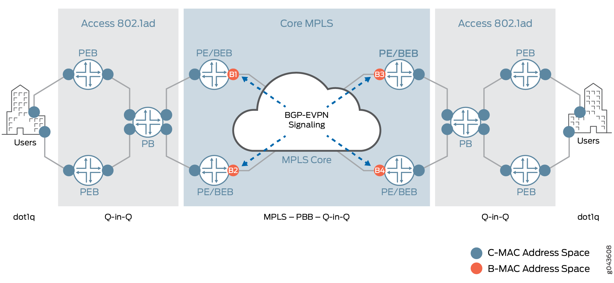
Figure 1 illustrates a PBB network, describing the PBB network elements and MAC address spaces.
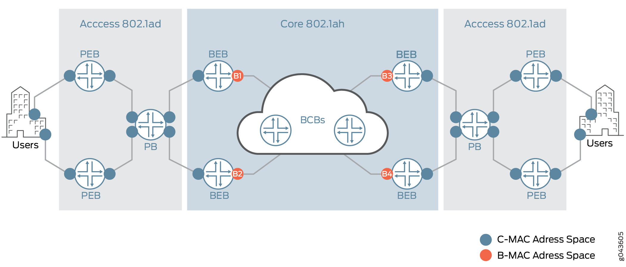
The PBB terms are:
PB—Provider bridge (802.1ad)
PEB—Provider edge bridge (802.1ad)
BEB—Backbone edge bridge (802.1ah)
BCB—Backbone core bridge (802.1ah)
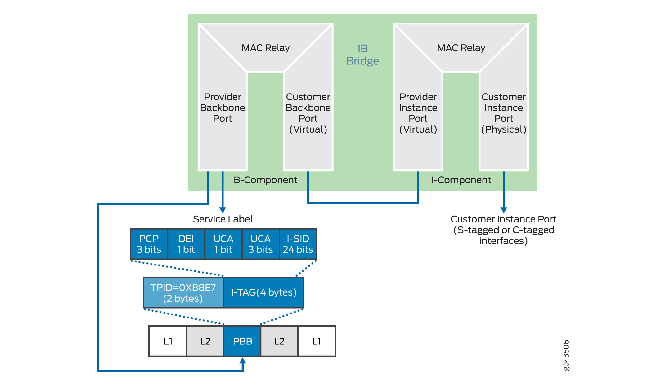
The BEB device is the first immediate point of interest within PBB, and forms the boundary between the access network and the core. This introduces two key components—the I-component and B-component in PBB.
I-component
The I-component forms the customer or access facing interface or routing instance. The I-component is responsible for mapping customer Ethernet traffic to the appropriate I-SID. At first, the customer Ethernet traffic is mapped to a customer bridge domain. Then each customer bridge domain is mapped to an I-SID. This service mapping can be per port, per port with service VLAN (S-VLAN), or per port with S-VLAN and customer VLAN (C-VLAN). The I-component is used to learn and forward frames based on the C-MAC addresses, and maintains a C-MAC-to-B-MAC mapping table that is based on instance tag (I-TAG).
Within the I-component there are two ports:
Customer Instance Port (CIP)
These ports are customer service instances at the customer-facing interfaces. Service definitions can be per port, per port with S-VLAN, or per port with S-VLAN and C-VLAN.
Provider Instance Port (PIP)
This port performs PBB encapsulation, such as pushing the I-TAG, source and destination B-MAC addresses, and PBB decapsulation, such as popping the I-SID, learning source B-MAC-to-C-MAC mapping, in the ingress direction.
B-component
the B-component is the backbone-facing PBB core instance. The B-component is used to learn and forward packets based on the B-MAC addresses. The B-component is then responsible for mapping the I-SIDs to the appropriate B-VLANs (in the case of PBB networks) or pushing and popping service MPLS labels for MPLS-based networks.
Within the B-component there are two ports:
Customer Backbone Port (CBP)
These ports are backbone edge ports that can receive and transmit instance-tagged frames from multiple customers, and assign backbone VLAN IDs (B-VIDs) and translate the I-SID on the basis of the received I-SID.
Provider Backbone Port (PBP)
These ports provide connectivity to the other bridges within and attached to the backbone. These are provider-facing ports. These ports support the S-VLAN component.
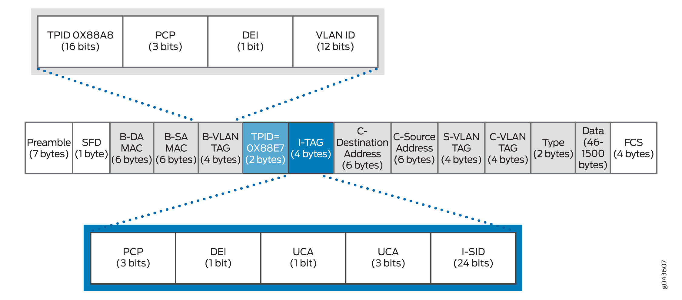
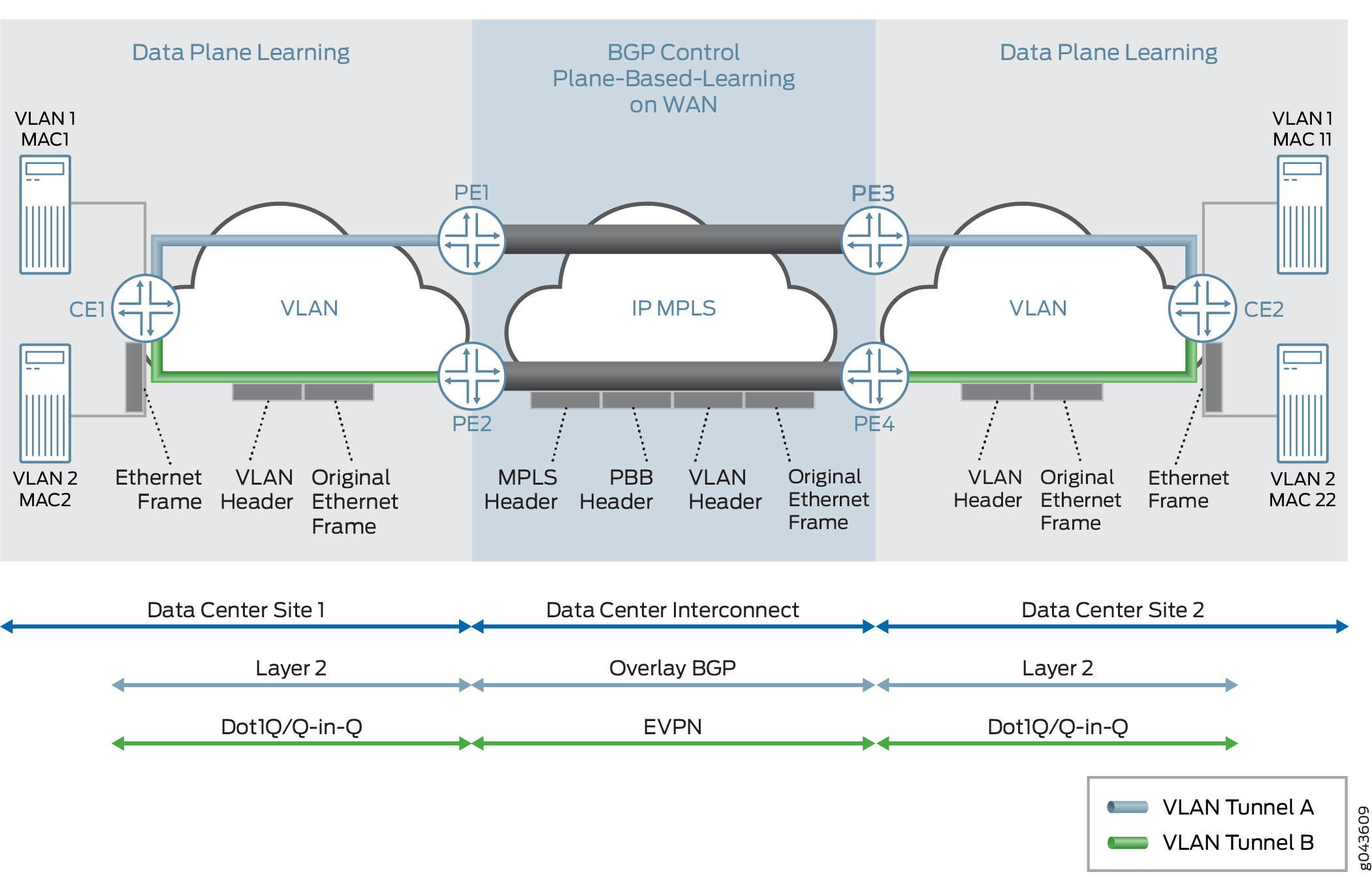
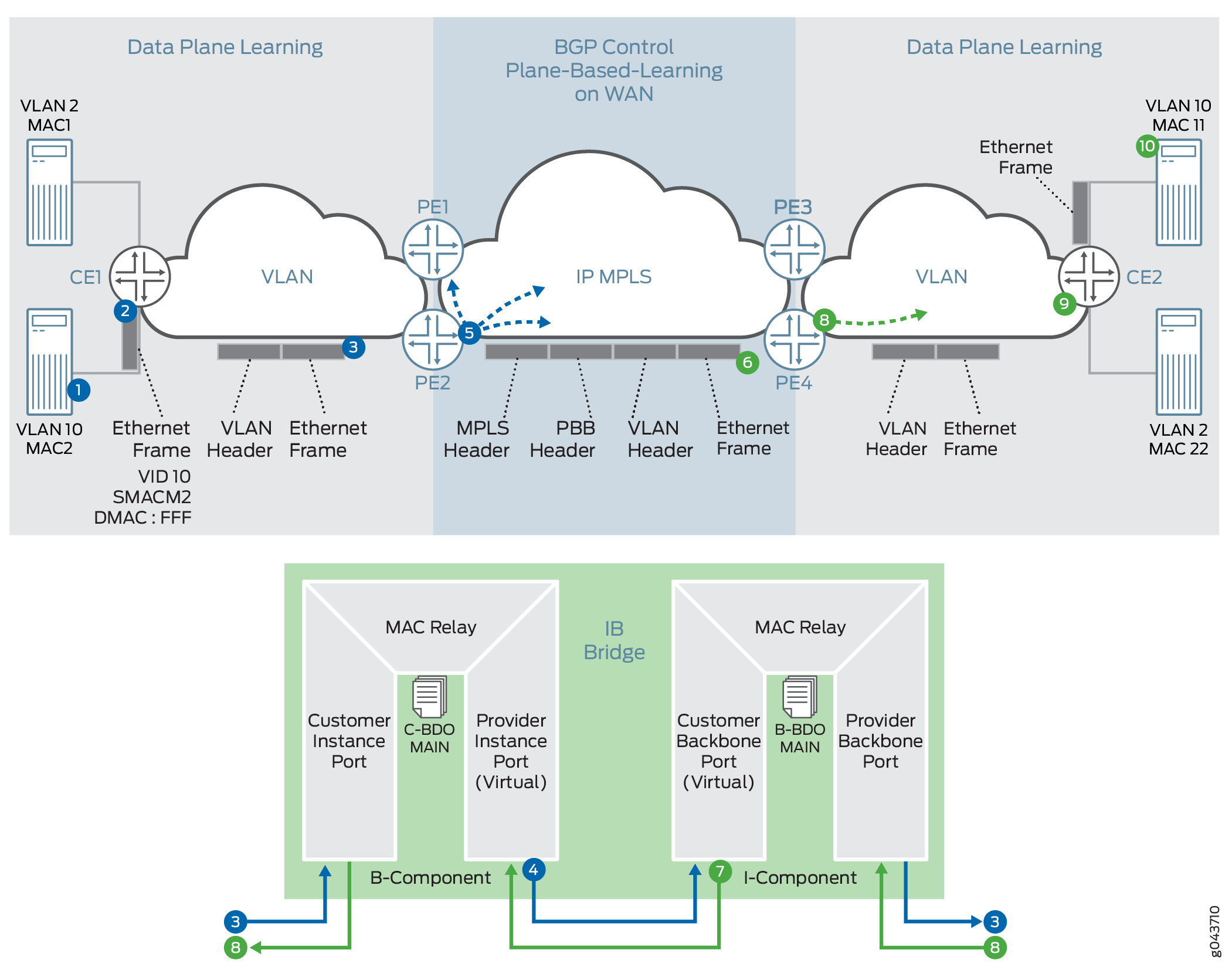
Figure 2 illustrates the key components of PBB. Figure 3 illustrates the PBB packet format.
Understanding EVPN
EVPN is a new standards-based technology that provides virtual multipoint bridged connectivity between different Layer 2 domains over an IP or IP/MPLS backbone network. Similar to other VPN technologies, such as IPVPN and VPLS, EVPN instances (EVIs) are configured on PE routers to maintain logical service separation between customers. The provider edge (PE) devices connect to customer edge (CE) devices, which can be a router, switch, or host. The PE devices then exchange reachability information using MultiProtocol BGP (MP-BGP) and encapsulated traffic is forwarded between them. Because elements of the architecture are common with other VPN technologies, EVPN can be seamlessly introduced and integrated into existing service environments.
The EVPN technology provides mechanisms for next-generation data center interconnection (DCI) by adding extended control plane procedures to exchange the Layer 2 (MAC address) and Layer 3 (IP address) information among the participating Data Center Border Routers (DCBRs). These features help address some of the DCI challenges, such as seamless VM mobility and optimal IP routing. Seamless VM mobility refers to the challenge of Layer 2 extension and maintaining connectivity in the face of VM mobility, and optimal IP routing refers to the challenge of supporting default gateway behavior for a VM's outbound traffic and triangular routing avoidance of a VM's inbound traffic.
The EVPN technology is used by the data center operator to offer multi-tenancy, flexible, and resilient services that can be extended on demand. This flexibility and resiliency can require using compute resources among different physical data centers for a single service (Layer 2 extension) and VM motion.
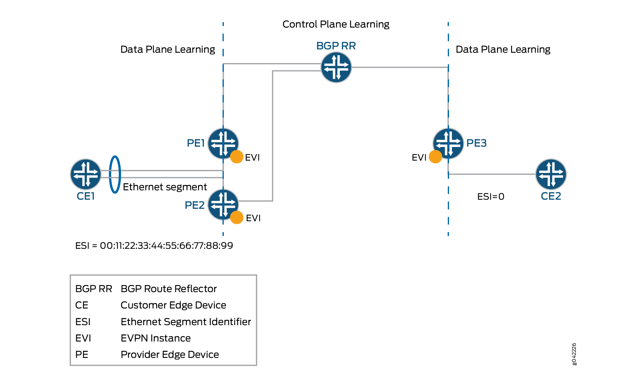
EVPN supports all-active multihoming, which allows a CE device to connect to two or more PE devices such that traffic is forwarded using all of the links between the devices. This enables the CE device to load-balance traffic to the multiple PE devices. More importantly it allows a remote PE device to load-balance traffic to the multihomed PEs across the core network. This load balancing of traffic flows between data centers is known as aliasing. EVPN also has mechanisms that prevent the looping of broadcast, unknown unicast, and multicast (BUM) traffic in an all-active multihomed topology.
We don't support IGMP snooping, MLD snooping, or PIM snooping multicast optimizations with PBB-EVPN.
Multihoming provides redundancy in the event that an access link or a PE device fails. In either case, traffic flows from the CE device toward the PE device use the remaining active links. For traffic in the other direction, the remote PE device updates its forwarding table to send traffic to the remaining active PE devices connected to the multihomed Ethernet segment. EVPN provides a fast convergence mechanism so that the time it takes to make this adjustment is independent of the number of MAC addresses learned by the PE device.
EVPN’s MP-BGP control plane allows live virtual machines to be dynamically moved from one data center to another, also known as VM motion. After a VM is moved to a destination server/hypervisor, it transmits a gratuitous ARP that updates the Layer 2 forwarding table of the PE device at the destination data center. The PE device then transmits a MAC route update to all remote PE devices which in turn update their forwarding tables. In this manner, an EVPN tracks the movement of the VM, also known as MAC Mobility. EVPN also has mechanisms to detect and stop MAC flapping.
The EVPN technology, similar to Layer 3 MPLS VPN, introduces the concept of routing MAC addresses using MP-BGP over the MPLS core. Some of the important benefits of using EVPNs include:
Ability to have a dual-active multihomed edge device
Provides load balancing across dual-active links
Provides MAC address mobility
Provides multi-tenancy
Provides aliasing
Enables fast convergence
PBB-EVPN Integration
The integration of PBB with EVPN is described in the following sections:
Integrating the PBB and EVPN Network Elements
In a PBB network, a huge amount of customer MAC (C-MAC) addresses are hid behind a drastically smaller number of backbone MAC (B-MAC) addresses, without the devices in the core having to learn and process all the individual customer states. The I-SID creates an encapsulation that enables a large number of services to be deployed. However, unlike modern networks that have a simple MPLS core composed of PE and provider devices, the devices in the PBB core need to act as switches, called the backbone core bridge (BCB), performing forwarding decisions based on B-MAC addresses. This causes incompatibility issues with modern MPLS networks, where packets are switched between edge loopback addresses using MPLS labels and recursion.
With the integration of PBB with EVPN, the BCB element in the PBB core is replaced with MPLS, while retaining the service scaling properties of the BEB PBB edge device. The B-component is signaled using EVPN BGP signaling and encapsulated inside MPLS using PE and provider devices. As a result, the vast scale of PBB is combined with the simplicity of a traditional basic MPLS core network and the amount of network-wide state information is significantly reduced, as opposed to regular PBB.
Figure 5 illustrates the PBB-EVPN integration using the different elements of a PBB and EVPN network.
PBB-EVPN Control Plane Initialization
In a PBB-EVPN network, B-MAC addresses are distributed over the EVPN core and C-MAC addresses are learned in the data plane and aggregated behind the B-MAC addresses.
Figure 6 illustrates the control plane handling in a sample PBB-EVPN network with four PE devices and two top-of-rack devices across two data centers.
The control plane handling at the Data Center Site 1 is as follows:
The C-MAC address lookup occurs and the C-MAC address is learned.
The B-MAC source address and I-SID are pushed on the packet.
Destination address lookup of C-MAC to B-MAC is done in the I-SID table. If the MAC address is present, the packet is routed using an EVPN MAC route; otherwise a multicast route is used.
This route gives the service label for the packet, which has PBB and also the original frame.
The control plane handling at the Data Center Site 2 is as follows:
At the disposition PE device, the packet is received with a single service label, indicating that it is a PBB frame.
The source address allocation of C-MAC to B-MAC is learned in the I-SID table.
The source address of the C-MAC is learned in the customer bridge domain (C-BD) MAC table.
Discovery of EVPN Routes in PBB-EVPN
PBB with Dot1ah functionality is implemented at the PE devices. In the case of PBB-EVPN, the PE devices implement the instance and backbone bridge functionality. Only B-MAC addresses are distributed in the control plane, the C-MAC addresses are learned in the data plane. The following EVPN routes are discovered on the different PE devices:
VPN Autodiscovery
When an EVPN instance (EVI) is configured on different PE devices, autodiscovery of the VPN happens first for discovering the EVPN endpoints. Each PE device that is configured with an EVI sends the inclusive multicast route.
The inclusive multicast route fields are as follows:
RD—Unique route distinguisher value per advertising PE device per EVI. The significance of the RD is local to a PE device.
TAG ID—Service ID equivalent to the I-SID value. One I-SID is assigned to one bridge domain under an EVI when service is supported. The TAG ID is set to 0 for the I-SID bundle service, where multiple I-SIDs are mapped to one bridge domain.
Originating IP addr—Loopback IP address.
P-Multicast Service Interface (PMSI) Attributes—Attributes required for transmitting the BUM traffic. There are two type of tunnels—point-to-multipoint LSP and ingress replication. In the case of ingress replication, the multicast label for BUM traffic is downstream assigned. In the case of point-to-multipoint LSP, the PMSI attribute includes the point-to-multipoint LSP identifier. If the multicast tree is shared or aggregated among multiple EVIs, the PE device uses the upstream assigned label to associate or bind to the EVI.
RT Extended Community—Route target associated with an EVI. This attribute is of global significance in EVPN.
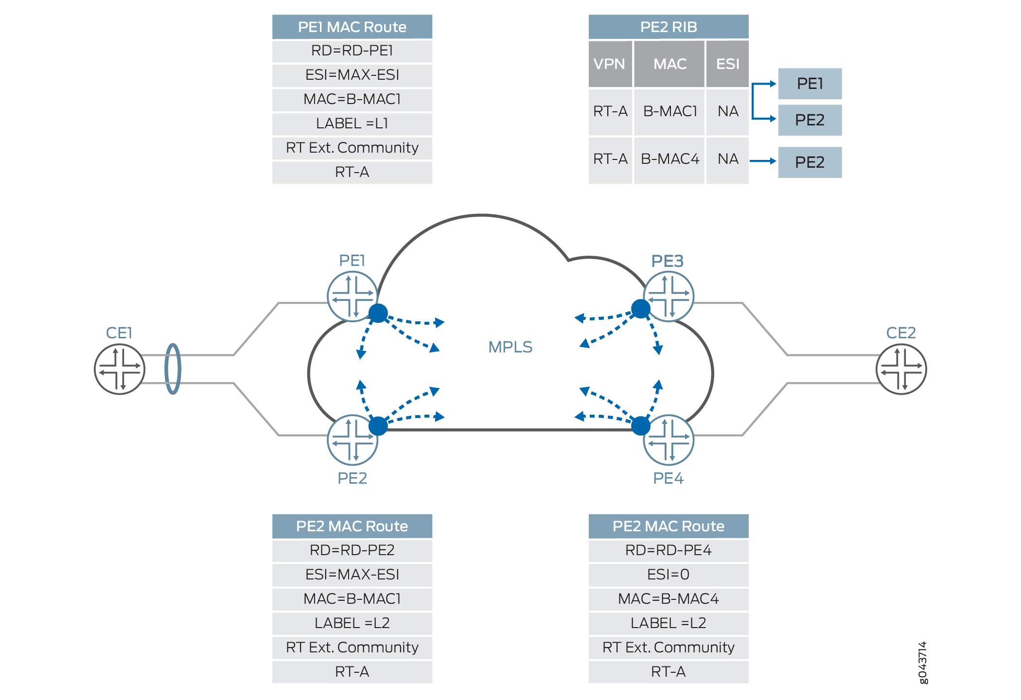
In Figure 7, each PE device sends the inclusive multicast route to each BGP neighbor. Device PE1 sends an inclusive multicast route to Devices PE2, PE3, and PE4 for VPN autodiscovery. The handling of BUM traffic is also illustrated in the figure. During the startup sequence, Devices PE1, PE2, PE3, and PE4 send inclusive multicast route that include the multicast label.
Ethernet Segment Discovery
The Ethernet segment route is encoded in the EVPN NLRI using the Route Type of value 4. This NLRI is used for discovering the multihomed Ethernet segment and for DF election.
ES-import route target, a transitive route target extended community, is also carried with the Ethernet segment route. ES-import extended community enables all the PE devices connected to the same multihomed site to import the Ethernet segment routes. The import of this route is done by the PE device that has the ESI configured. All other PE devices discard this Ethernet segment route.
Figure 8 provide details about the procedure of Ethernet segment route for multihomed Ethernet segment autodiscovery.
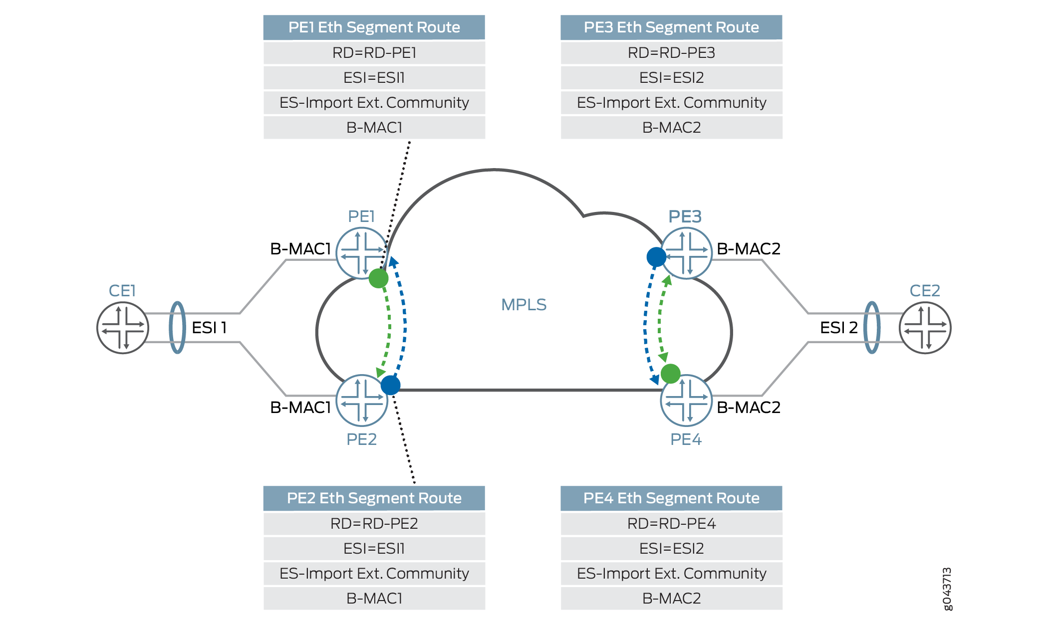
In this figure, Devices PE1 and PE2 are connected to a multihomed segment with ESI value of ESI1 and B-MAC address of B-MAC1. In the case of an active-active multihomed segment, this B-MAC should be the on Devices PE1 and PE2. Similarly, Devices PE3 and PE4 are active/active multihomed for ESI2 with B-MAC address of B-MAC2. Devices PE1 and PE2 send the Ethernet segment route for ESI1, which is received by Devices PE3 and PE4, but is ignored because the devices are not configured for ESI1. Only Devices PE1 and PE2 are in one redundant group and the DF election is performed in this group. Similarly, Devices PE3 and PE4 are in another redundant group and either Device PE3 or PE4 is selected as the DF.
Ethernet MAC Routes Discovery
Ethernet MAC Advertisement route is used for distributing B-MAC addresses of PE nodes. The MAC advertisement route is encoded with following fields:
MAC address field contains B-MAC address.
Ethernet Tag field is set to 0.
Ethernet segment identifier field must be set to 0 (for single-homed segments or multihomed segments with per-I-SID load balancing) or to MAX-ESI (for multihomed segment with per-flow load balancing).
Label is associated with unicast forwarding of traffic from different PE devices.
RT (route target) extended community associated with its EVI.
Figure 9 illustrates the MAC route advertisement in PBB-EVPN.
Differences Between PBB-EVPN and EVPN
Table 1 and Table 2 list the differences between PBB-EVPN and pure EVPN for Layer 2 networks in the context of different route types and route attributes, respectively.
Route |
Usage |
Applicability |
|---|---|---|
Ethernet autodiscovery route |
|
EVPN only |
MAC advertisement route |
|
EVPN PBB-EVPN |
Inclusive multicast route |
Multicast tunnel endpoint discovery |
EVPN PBB-EVPN |
Ethernet segment route |
|
EVPN PBB-EVPN |
Attribute |
Usage |
Applicability |
|---|---|---|
ESI MPLS lable extended community |
|
Ethernet autodiscovery route |
ES-import extended community |
Limit the import scope of the Ethernet segment routes. |
Ethernet segment route |
MAC mobility extended community |
|
MAC advertisement route |
Default gateway extended community |
Indicate the MAC or IP bindings of a gateway. |
MAC advertisement route |
PBB-EVPN Packet Walkthrough
Based on the PBB and EVPN configuration on different PE devices of the network, the Ethernet segment, B-MAC address reachability, and multicast routes are already programmed on different PE devices in the EVPN cloud. The packet walkthrough of PBB-EVPN includes the handling of the following traffic types:
Handling BUM Traffic in PBB-EVPN
Figure 10 illustrates the PBB-EVPN control plane and BUM traffic handling.
The PBB-EVPN handling of BUM traffic over the EVPN cloud is as follows:
After Server A boots up, Server A attempts to send traffic to Server B. Server A does not have the ARP binding in the ARP table for Server B, so Server A builds an ARP broadcast request and sends it. The contents of the ARP packets are VLAN 10, S-MAC=M2 (server A interface MAC), Destination MAC=ff.ff.ff.ff.ff.ff, source IP address=IP address of Server A or VM IP address, and destination IP address=IP address of Server B. Ether type of packet for ARP is 0x0806. Layer 2 frame is sent to Devie CE1.
Device CE1 does the Layer 2 switching operation on this frame. Because this is a Layer 2 broadcast frame, the frame is classified to an interface and based on the bridge domain configuration for this service and broadcast behavior. The packet is forwarded to all the members of the bridge domain except to the one on which it was received. There might be VLAN translation, such as push, pop, or translate, done on this frame. This frame is sent over to Device PE2. This frame might be untagged, single tagged, or Q-in-Q.
After Device PE2 receives this frame, at first it goes through the classification engine to classify the frame into a service. Based on the classification result interface (that is, the Customer Instance Port [CIP]) the service is identified. The source MAC address is learned (if it is not present in the MAC table). This classification results in the C-BD. Because this frame is a broadcast frame, it is sent to all the member interfaces of this bridge domain. One of the member interfaces of this bridge domain is the Provider Instance Port (PIP) interface. Now the packet is formed based on the I-SID configured for this PIP interface. The outer header of the packet at the PIP egress interface is formed based on the following information:
I-SID—Configured I-SID value on this PIP interface.
Source MAC address—B-MAC address configured or autogenerated for this frame.
Destination MAC address—Based on the per-I-SID mapping table that is built based on the source C-MAC-to-B-MAC address learning and the destination C-MAC-to-B-MAC address. For BUM traffic, the default value of the bridge destination address (B-DA) is the Backbone Service Instance Group address. When the B-DA of a frame is a Backbone Service Instance Group address, the normal behavior is to deliver the frame to all Customer Backbone Ports (CBPs) reachable within the backbone VLAN (B-VLAN) to which the backbone service instance is mapped. Filtering based on I-SID by the egress CBP ensures that frames are not transmitted by CBPs that are not part of the backbone service instance.
Layer 2 Ethernet type—0x88E7.
Payload—Customer frame.
The I-SID-formed packet is sent to the CBP for identifying the backbone bridge domain (B-BD) associated with the I-SID.
Lookup in the B-BD is done to send the packet to the right destination. Because this frame is a broadcast frame and the destination B-MAC is a multicast address (00-1E-83-<ISID value>), the packet needs to be handled as the ingress replication (that is, VPLS edge flood next hop) for EVPN. This next hop pushes the service label (multicast MPLS label associated with B-VLAN per peer ID and bridge VLAN ID). The MPLS packet is formed and sent over the MPLS cloud for Devices PE1, PE3 and PE4.
The frame is received by Device PE4 as a MPLS packet. The bridge domain identification is accomplished by doing an MPLS label L1 lookup in the mpls.0 routing table. The MPLS lookup points to the table next hop for the bridge domain next hop. After the bridge domain is identified, the packet is identified as a broadcast packet. The BUM composite flood next hop is executed, and this next hop points to the CBP.
The egress interfaces are identified. One of the egress interfaces is a PIP interface where the I-SID is configured, and I-SID based filtering (MAC filtering) is applied for filtering the frame. The source C-MAC-to-B-MAC address is learned for the I-SID MAC mapping table. This table is used for building the destination B-MAC address for unicast traffic. The outer I-SID header is popped from the customer Layer 2 frame. The customer bridge domain (C-BD) is found based on the I-SID classification to the PIP interface.
The source C-MAC address is learned. The destination C-MAC lookup is done. This is a broadcast frame, and based on the BUM handling (flood next hop), the frame is forwarded to all the member of the C-BD, except the member interface on which this frame was received.
Device CE2 receives this frame. Service classification is done based on the frame VLAN. Based on the classification, the bridge domain forwarding service is found and MAC learning is done. Because the frame is a broadcast frame, it is handled by flood next hop.
Server B receives the ARP request packet and sends the ARP reply to Server A.
Handling Unicast Traffic in PBB-EVPN
Figure 11 illustrates the PBB-EVPN control plane and unicast traffic handling in the form of an ARP reply from Server B.
For the unicast traffic flow, it is assumed that both the data and control plane MAC learning has already happened.
Server B generates an ARP reply. The contents of the ARP packets are VLAN 10, S-MAC=MAC11 (Server B interface MAC), destination MAC=MACA, source IP address=IP address of Server B or VM IP address, and destination IP address=IP address of Server A. This frame is forwarded to top-of-rack B.
After receiving the frame, the CE device classifies the incoming frame. Based on the interface family, the bridge domain associated with the interface is identified. Source MAC address learning takes place on the bridge domain. Next the bridge domain destination MAC (MACA) lookup is done, and the lookup provides the Layer 2 egress interface. The output feature of the egress interface is applied before the CE device sends the frame to the egress interface.
Layer 2 encapsulated frame is received by Device PE4. The Layer 2 service classification is done to identify the customer bridge domain (C-BD) associated with this frame. The source MAC address (MAC11) learning is done in the context of the C-BD on the CIP interface.
Destination MAC lookup in the context of C-BD points to the PIP interface. At this point , the PIP interface egress feature list is executed. Based on the feature list, the outer I-SID header is pushed on the original Ethernet frame.
Source MAC—B-MAC of Device PE4
Destination MAC—B-MAC of Device PE2 (lookup result in I-SID C-MAC-to-B-MAC table)
I-SID—Configured value of I-SID
Layer 2 Ether typ—0x88E7
The destination MAC address (B-MAC of Device PE2) lookup is done in the B-BD MAC address table. This lookup results in a unicast next hop (that is, an EVPN next hop). This next hop contains a unicast MPLS service label. This label is distributed through the multiprotocol BGP (MP-BGP) control plane. The downstream peer allocates this MPLS service label. Allocation of this label can be per EVI; per EVI and VLAN; per EVI, VLAN, and attachment circuit; or per MAC address. Based on the information in the next hop, the MPLS packet is formed and forwarded on the MPLS network.
Device PE2 receives the frame. It is identified as an MPLS packet. The MPLS label lookup is done in the mpls.0 routing table. This lookup results in the table next hop. This lookup results in the B-BD table. The B-MAC rule (that is, source B-MAC is destination B-MAC) and I-SID filtering (CBP configured ISID=packet ISID) rules are applied. Based on the received frame I-SID, CBP is identified and B-VLAN is popped.
The frame header is passed to the PIP interface for further processing. The C-MAC address (M11 to B-MAC-PE2) to B-MAC mapping is learned in the I-SID table. The outer I-SID header is popped.
The inner source MAC address is learned on the PIP interface in the context of C-BD. The inner destination MAC address lookup is done, resulting in the egress CIP interface.
The CE device receives the Layer 2 frame, and Layer 2 forwarding is done.
Server A receives the unicast ARP reply packet from Server B.
Handling Path Forwarding in PBB-EVPN
In a PBB-EVPN network, a frame can come from either the customer edge (CE) side (bridge interface) or the MPLS-enabled interface (core-facing interface).
The packet flow for packets received from the CE side is as follows:
If the frame is received from a CE interface, the interface belongs to the bridge family, and the MAC address lookup and learning are done in the customer bridge domain (C-BD) context. The result of the lookup is a unicast MAC route or a flood MAC route.
The next lookup is done in the I-SID MAC table to determine the destination B-MAC associated with the destination C-MAC.
The I-SID header is prepended to the packet.
The next lookup is done in the B-BD because the PIP interface belongs to the bridge family.
The B-BD lookup points to either the unicast MAC route or the flood MAC route and this route points to either the EVPN indirect multicast next hop or the unicast indirect next hop.
The packet flow for packets received from the core side is as follows:
If the frame is received from the core-facing interface, the interface belongs to the MPLS family, and the MPLS label lookup is done in the mpls.0 routing table next hop. The result of this lookup is the routing instance context.
The next lookup is done based on the I-SID from the packet to the BBD lookup.
If the BBD is found, then I-SID based filtering rules are applied, where the I-SID configured MAC should match the packet source B-MAC, then the frame is dropped.
The I-SID MAC table is updated for the destination B-MAC associated with the destination C-MAC for building the C-MAC-to-B-MAC association.
The I-SID header is removed and C-BD is found based on the PIP interface.
The next lookup is done in the C-BD because the PIP interface belongs to the bridge family.
The C-BD lookup points to either a unicast MAC route or a flood MAC route, and this route points to a CE interface or flood route.
Handling MAC Mobility in PBB-EVPN
Figure 12 illustrates PBB-EVPN MAC mobility from the point of the forwarding and control plane.
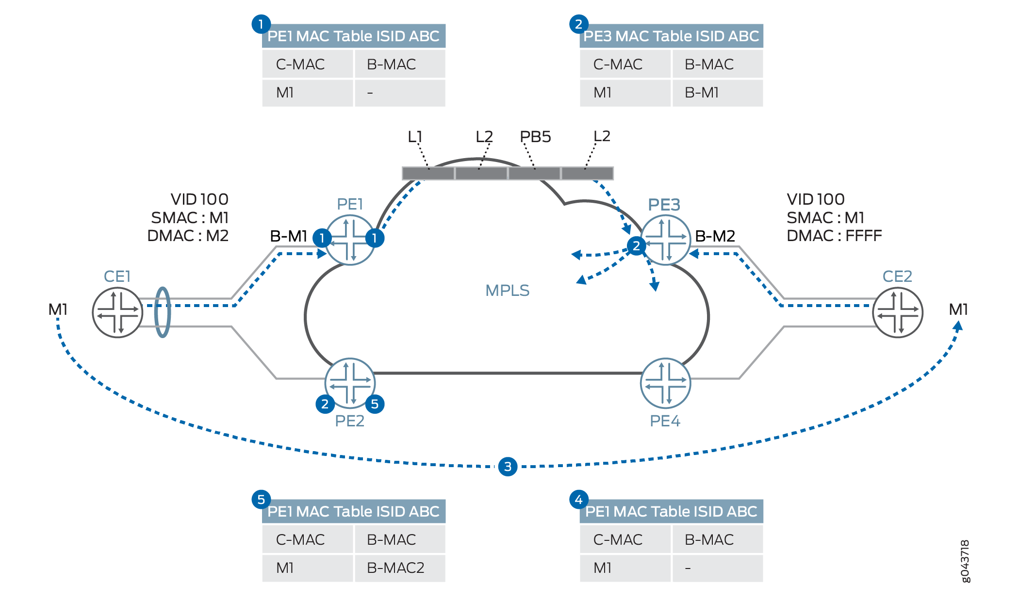
MAC mobility from the point of the forwarding and control plane is handled as follows:
Device PE1 learns the C-MAC address, M1, on the local port and forwards it across the core according to the destination-C-MAC-to-remote-B-MAC mapping. This mapping is either statically configured or learned through the data plane. If the destination-C-MAC-to-remote-B-MAC mapping is not found in the I-SID mapping table, then the remote B-MAC is derived by using the I-SID.
Device PE3 learns the C-MAC address, M1, through the B-MAC address, B-M1, from the dataplane.
Customer M1 is moved from Device CE1 to behind Device CE2.
When Customer M1 wants to communicate with a customer behind Device CE1, a broadcast traffic with VID: 100, Source MAC: M1, and destination MAC: ff.ff.ff.ff.ff.ff is sent. Device PE3 learns the MAC M1 in the C-BD MAC table and updates the M1 location in the I-SID mapping table.
Device PE1 receives the packet and M1 is learned and updated in the I-SID mapping table as reachable through the remote MAC is B-M2.
Handling End-to-End OAM for PBB-EVPN
You can run provider-level Operation, Administration, and Maintenance (OAM) by running connectivity fault management (CFM) on the inward or outward facing maintenance endpoints (MEPs) either on the PIP interface or over the EVPN service.
Currently, the designated forwarder (DF) election is decided based on the DF election algorithm and it is the local decision of the PE devices. This is useful in an end-to-end service handling scenario, where the decision of DF election can be done with operator’s consent as well and vice versa. Another scenario in which it might be useful to influence the DF role per service basis or propagating the DF to a CE device is for multihomed networks, where there is no direct link between the CE and PE devices.
Handling QoS and Firewall Policer Support for PBB-EVPN
Table 3 provides details about the QoS and firewall features that are supported in the context of PBB-EVPN integration.
Feature |
Description |
Support on round-trip time (RTT) |
Support on CE Interface |
Support on Core Interface |
|---|---|---|---|---|
Classification |
Fixed classification to one FC |
Yes |
Yes |
Yes |
Behavior aggregate (BA) and multifield classifier (MF) classification for inner output VLAN 802.1p bit |
Yes |
Yes |
Yes |
|
BA and MF classification based on drop eligible indicator (DEI) and priority code point (PCP) fields |
No |
Not required |
No |
|
BA and MF classification based on MPLS experimental (EXP) field |
No |
No |
Yes |
|
CoS Marking |
802.1p to I-SID PCP and DEI fields: Customer VLAN 802.1p |
No |
By default, 802.1p is mapped to PCP and DEI fields |
Yes |
802.1p to MPLS EXP field: Customer VLAN 802.1p |
No |
No |
Yes |
|
MPLS EXP field to I-SID PCP and DEI fields |
No |
Default behavior |
No |
|
EXP field to 802.1p |
No |
Yes |
No |
|
QoS shaping |
Hierarchical scheduling and shaping on ingress device |
No |
Yes |
Yes |
Hierarchical scheduling and shaping on egress device |
No |
Yes |
Yes |
|
Firewall filter |
Filtering BUM traffic |
Unknown traffic only |
Broadcast and multicast traffic only |
Broadcast and multicast traffic only |
I-SID-based firewall filter |
No |
No |
No |
|
Customer VLAN-based filter |
No |
Yes |
Yes |
|
Policer (2 rate 3 color) |
Ingress direction |
No |
Yes |
Yes |
Egress direction |
No |
Yes |
Yes |
Implementation Overview of PBB-EVPN Integration
The following sections provide use case scenarios for PBB-EVPN integration for DCI.
- PBB-EVPN Failure Scenarios
- PBB-EVPN I-SID Use Case Scenarios
- VPLS Integration with PBB-EVPN Use Case Scenario
- PBB-EVPN Redundancy Use Case Scenarios
PBB-EVPN Failure Scenarios
There are different PBB-EVPN failure scenarios that should be taken care of while providing an end-to-end solution. These failure scenarios can be of the following types:
Segment Failure
A segment, or CE-facing link, failure is handled in the activce/active and active/standby multihoming redundancy modes.
Figure 13 shows the handling of segment failure for flow-based load balancing at Device CE1.
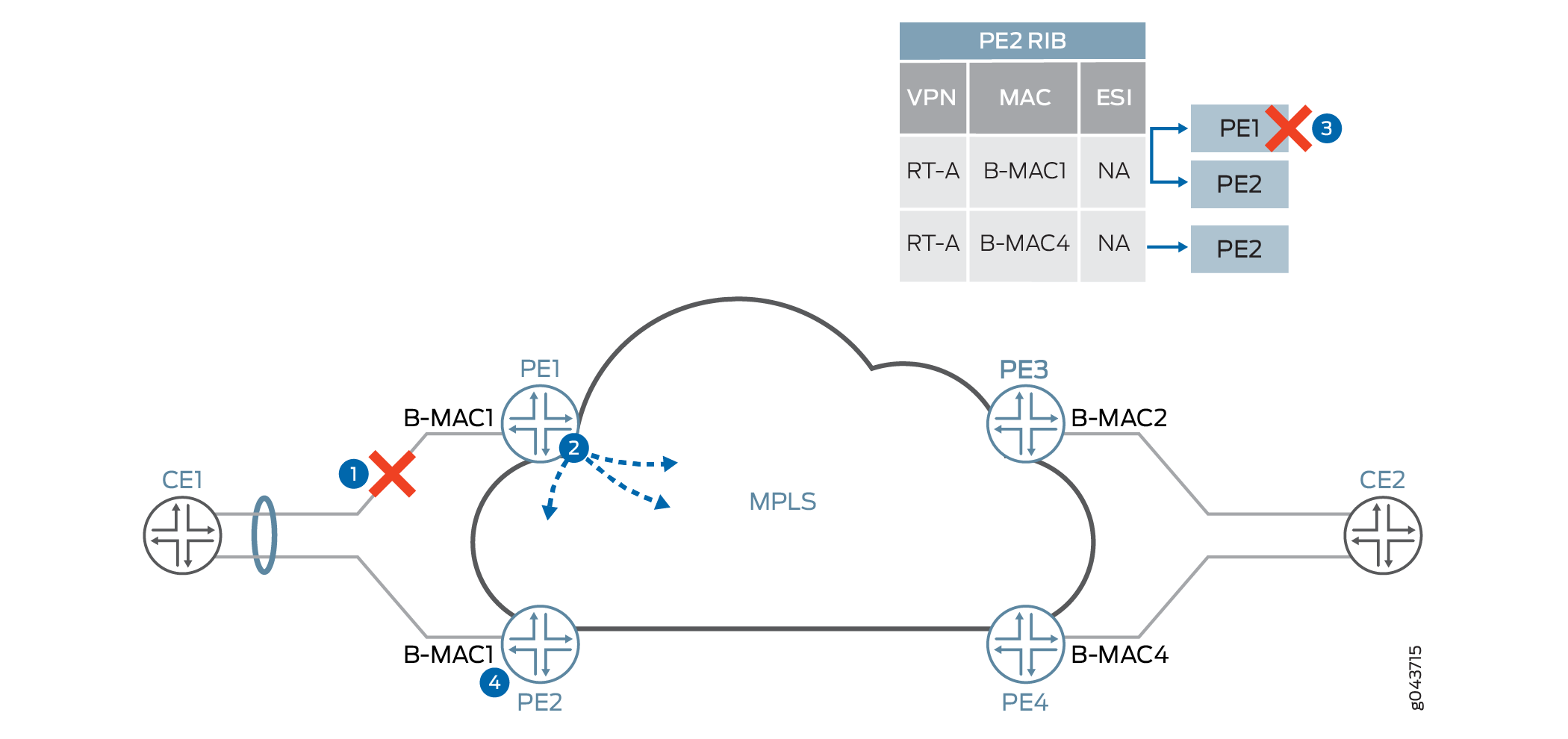
A segment failure in PBB-EVPN is handled as follows:
Ethernet link between Devices CE1 and PE1 failed due to fiber cut or the interface is down. Device PE1 detects the failed segment.
Device PE1 withdraws the B-MAC address that is advertised for the failed segment (B-M1).
The CE1-facing link goes down. If the link failure happens in the single-active redundancy mode or no redundancy case, the C-MAC flush is also done.
The C-MAC address flushing happens in two ways:
If Device PE2 uses the shared B-MAC address for multiple I-SIDs, it notifies the remote PE device by readvertising the B-MAC address with the MAC mobility extended community attribute by incrementing the value of counter. This causes the remote PE device to flush all C-MAC addresses associated with the B-MAC address for Device PE1.
If Device PE2 uses the dedicated B-MAC address, then it withdraws the B-MAC address associated with the failed segment and sends it to Devices PE2, PE3, and PE4.
After receiving the B-MAC withdraw from Device PE1, Device PE3 removes PE1 reachability for B-MAC1 from its forwarding table. Reachability of B-MAC1 through Device PE2 still exists.
The DF election is rerun on Device PE2 for all the I-SIDs for the Ethernet segment ESI.
Node Failure
A node, or PE device, failure scenario is similar to a segment failure from the point of view of CE side failure handling, but it is different from core side failure handling. In the case of core side failure handling, EVPN depends on the BGP session timeout for clearing the state of the EVPN sessions on affected PE devices.
Figure 14 illustrates a node failure scenario for node failure handling.
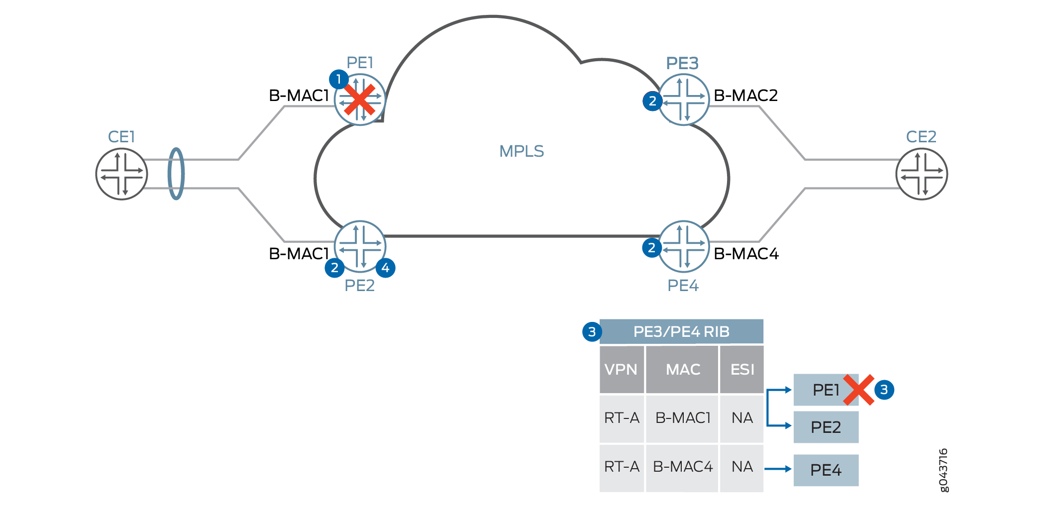
Device PE1 failed and the CE side switchover to Device PE2 is done by an interface down event.
Devices PE2, PE3, and PE4, or BGP route reflector, detect the BGP session timeout with Device PE1.
As soon as the BGP session timeout happens, Devices PE3 and PE4 remove Device PE1 from the forwarding table by marking the Device PE1 next hop as unreachable or deleted. In the case of single-active redundancy mode, the I-SID table for C-MAC-to-B-MAC mapping table has to be flushed or updated. In the case of active/active redundancy mode, it is not required to flush the I-SID table, because the same B-MAC address is used for both Devices PE1 and PE2 for a given EVI.
At Device PE2, after a BGP timeout, the DF election algorithm is rerun and Device PE2 becomes the DF for all I-SIDs on an affected Ethernet segment.
Core Failure
The handling of core side isolation in the EVPN network is similar to the PE side failure, with some differences in handling of the CE device or Ethernet segment.
Figure 15 provides details about the handling of core isolation.
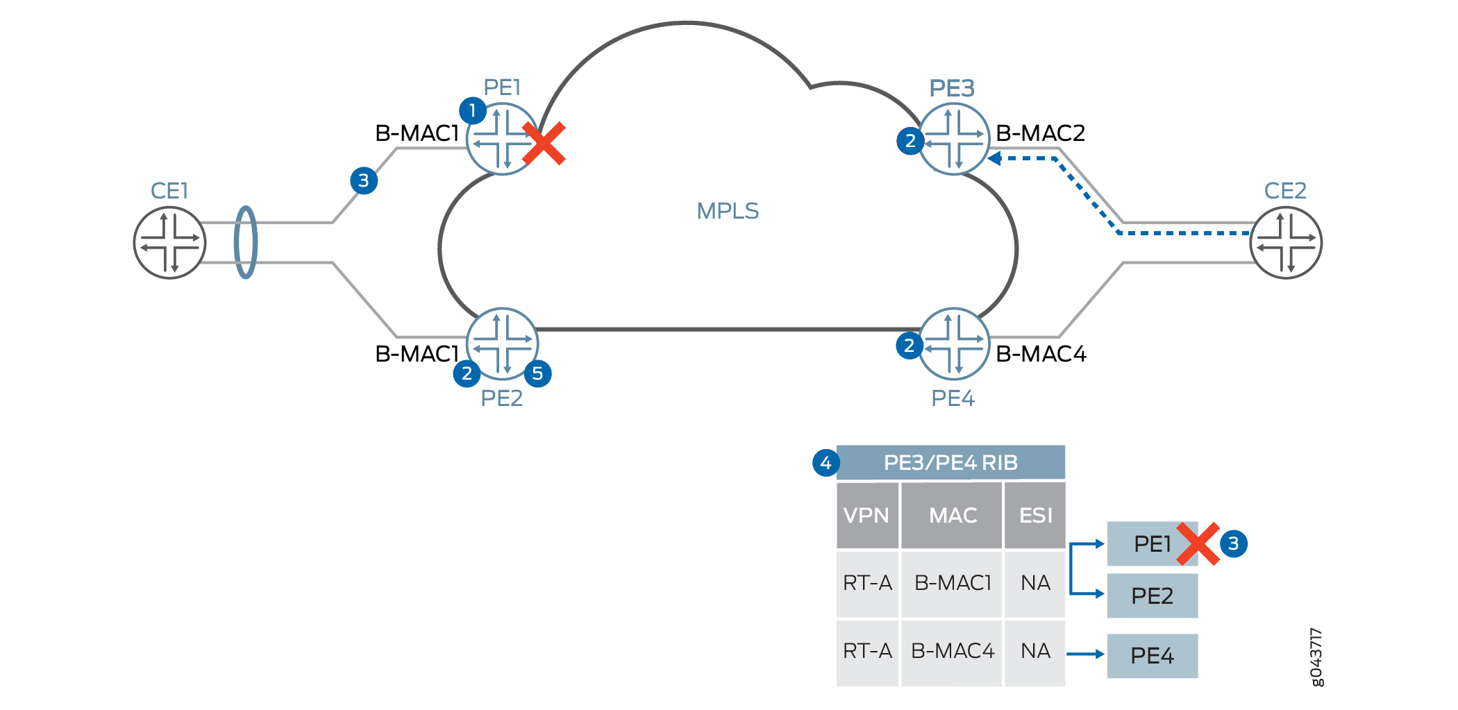
Core isolation in PBB-EVPN is handled as follows:
Device PE1 looses connectivity to the core.
Devices PE2, PE3, and PE4, or BGP route reflector, detect the BGP session timeout with Device PE1.
Device PE1 sends an LACP OUT_OF_SYNC message to Device CE1 to take the port out of the bundle.
Device PE2, or BGP route reflector, detects the BGP session timeout with Device PE1.
Device PE2 reruns the DF election and is selected as the DF for all the I-SIDs on the segment.
PBB-EVPN I-SID Use Case Scenarios
I-SID Base Service
In the case of the I-SID base service, there is one-to-one mapping between a bridge domain and an EVI. In this case, there is no need to carry the I-SID in the MAC advertisement route, because the bridge domain ID can be derived from the route target (RT) associated with this route. The MPLS label allocation is done on a per-EVI basis.
Figure 16 provides an overview of the I-SID base use case scenario.
In the case of I-SID load balancing, where load balancing of traffic is done on a per-service basis from the originating CE link aggregation group (LAG) configuration, there are two models for B-MAC addresses:
Shared source B-MAC
In this model, all I-SIDs from an Ethernet segment share one source B-MAC address. This model has limitations from the point of view of B-MAC withdrawal because of service failure. The remote PE device needs to flush B-MAC-to-C-MAC mapping for all I-SIDs . This creates problem for convergence because MAC flush is done for all I-SIDs.
Unique source B-MAC per I-SID
Unique unicast B-MAC addresses (one per I-SID) are allocated per multihomed Ethernet segment. The DF filtering is applied to unicast and multicast traffic, in both the core-to-segment and segment-to-core directions.
I-SID-Aware Service
In the case of I-SID-aware service, multiple I-SIDs can be mapped to the same EVI. But there is one-to-one mapping between a bridge domain and an I-SID. The Ethernet Tag ID must be set to the I-SID in the BGP routes advertisements. The MPLS label allocation is done on a per-EVI or per-EVI/I-SID basis so that the PBB can be terminated at the ingress PE device and recreated at the egress PE device.
VPLS Integration with PBB-EVPN Use Case Scenario
In this use case scenario, VPLS is one cloud that is getting integrated with PBB-EVPN by using logical tunnel interfaces. The logical tunnel interface is being terminated into the customer bridge domain (C-BD). MAC address learning from the VPLS cloud is happening in the context of the C-BD. The C-bridge domain gets mapped to the backbone bridge domain and going to the EVPN cloud.
PBB-EVPN Redundancy Use Case Scenarios
Single Active Redundancy Use Case Scenario
In this use case scenario, a CE device is multihomed to multiple PE devices. The Ethernet segment for this scenario is defined by configuring the same ESI ID on multiple physical interfaces or aggregated Ethernet interfaces on the PE devices along with the mode of operation. In this mode of operation, only one PE device (that is, the DF) is allowed to forward the traffic to and from this Ethernet segment for BUM traffic. The DF election is done based on each ESI in an EVI and by taking the lowest configured I-SID into consideration. This also depends on this number of PE devices to which a segment is multihomed. The service carving is achieved by putting different I-SIDs in different EVIs. The DF election is similar to the DF election in the VLAN-based EVPN. A default timer of 3 seconds is used for reception of Ethernet segment routes from other PE nodes, and this timer can be configured with the same command as used in EVPN—the designated-forwarder-election hold-time statement.
In case of PBB-EVPN, the Ethernet autodiscovery route is not used. This mode is specified in the B-MAC advertisement route. In a single-homed or multihomed setup, with the single-active mode, the ESI field must be set to 0 in the B-MAC route advertisement. If ESI 0 is used in the MAC advertisement route, then I-SID-based load balancing is performed. An I-SID value can serve as a single home, an active/standby scenario, or an active/active scenario. It cannot, however, be used in a mixed mode of operation.
Figure 17 provides the use case scenario for active/standby multihoming along with DF election.
Active/Standby Redundancy Use Case Scenario
In the case of the active/active redundancy use case scenario, the DF election is used for handling the BUM traffic. In the case of PBB-EVPN, split horizon of EVPN is not used for filtering the BUM traffic. Instead, BUM traffic is filtered by filtering the destination B-MAC, where the configured B-MAC is the same as the received packet B-MAC; therefore that packet is from the same segment.
The aliasing approach is the same as the EVPN, but the B-MAC route is advertised by setting the ESI field to MAX-ESI. When the remote PE device receives the B-MAC route with the MAX-ESI value, then the remote PE device does the load balancing between Devices PE1 and PE2.
Active/Active Redundancy Use Case Scenario
In a PBB-EVPN active-active multihomed network, all the multihomed PE devices require identical MAC installations. For this purpose, BGP is used to sync the source C-MAC addresses (on the CE side) or the remote C-MAC addresses (from the core) across the multihomed PE devices for same ESI.
To enable MAC sync:
For the source C-MAC address sync:
Configure per-packet-load-balancing on the CE device.
Ensure that there are minimum flows per source C-MAC, so that each source C-MAC takes both links toward the multihomed PE devices at least once. This ensures that both the multihomed PE devices learn each source C-MAC.
For remote C-MAC address sync:
Ensure that there are minimum flows per remote C-MAC, so that each remote C-MAC takes both links(aliasing) towards the multihomed PE devices at least once while traversing the core. This ensures that both the multihomed PE devices learn each remote C-MAC.
Configuration Overview of PBB-EVPN Integration
The PBB-EVPN configuration is done using the following models:
One-to-one mapping between the I-SID and the bridge domain
In this configuration model, there is a shared EVPN instance (EVI) between different services, although there is one-to-one mapping between the bridge domain and the I-SID.
Many-to-one mapping between the I-SID and the bridge domain
In this configuration model, virtual switch configuration is used to allow multiple I-SIDs to be mapped to one bridge domain. This model allows only one bridge domain in a given EVI, and all other bridge domains are mapped to the other Layer 2 services.
Sample PBB-EVPN Port Configuration:
Provider Backbone Port (PBP) Configuration:
routing-instances {
    evpnA {
        instance-type virtual-switch;
        route-distinguisher 192.0.2.1;
        vrf-target target:65221:111;
        protocols {
            evpn {
                label-allocation per-instance;
                extended-isid-list [10000 10401 20000-20001]
            }
        }
    }
}
Customer Backbone Port (CBP) Configuration:
interfaces {
    cbp {
        flexible-valn-tagging;
        unit 0 {
            family bridge {
                interface-mode trunk;
                isid-list [10000 10401 20000-20001] [all];
            }
        }
    }
}
Provider Instance Port (PIP) Configuration:
interfaces {
    pip {
        flexible-valn-tagging;
        unit 0 {
            family bridge {
                interface-mode trunk;
                isid-list [20000 20001];
            }
        }
        unit 1 {
            family bridge {
                interface-mode trunk;
                isid-list [10000 10401];
            }
        }
    }
}
Customer Instance Port (CIP) Configuration:
interfaces {
    ge-4/0/0 {
        flexible-valn-tagging;
    esi 1 primary;
        unit 0 {
            family bridge {
                interface-mode trunk;
                vlan-id-list [1-399 500 800];
            }
        }
        ge-7/0/0/ {
            flexible-vlan-tagging;
            unit 0 {
                family bridge {
                    interface-mode trunk;
                    vlan-id-list [1-401];
                }
            }
        }
        ge-8/0/0/ {
            flexible-vlan-tagging;
            unit 0 {
                family bridge {
                    interface-mode trunk;
                    vlan-id-list [500-501];
                }
            }
        }
}
Sample PBB-EVPN Routing Instance Configuration:
Provider Routing Instance Configuration:
routing-instances {
    EVPN A {
        instance-type virtual-switch;
        route-distinguisher 192.0.2.1;
        vrf-target target:65221:111;
        protocols {
            pbb-evpn {
                label-allocation per-instance;
                extended-isid-list [10000 10401 20000] [all];
            }
            evpn {
                label-allocation per-instance;
                extended-vlan-list 1000;
            }
        }
        interface cbp.0;
        bridge-domains {
            B-BD1 {
                isid-list 10000;
            }
            B-BD2 {
                isid-list 10401;
            }
            B-BD3 {
                isid-list 20000;
            }
            B-BD4 {
                isid-list 1000;
            }
        }
        pbb-options {
            vlan-id 1000 isid-list [20001];
            default-bvlan 22;
        }
    }
}
Customer Routing Instance Configuration:
routing-instances {
    PBN-1 {
        instance-type virtual-switch;
        interface ge-4/0/0.0;
        interface pip.0;
        bridge-domains {
            customer-BDs {
                vlan-id-list [1-399 500 800];
            }
        }
        pbb-options {
            peer-instance EVPN A;
            source-bmac <mac-address>;
            service-groups {
                pbb-1-isid {
                    source-bmac <mac-address>;
                    isid {
                        isid-1 {
                            isid 20000 vlan-id-list [1-399 500] [all];
                            source-bmac <mac-address>;
                            map-dest-bmac-to-dest-cmac <b-mac> <c-mac>;
                            }
                            isid-2 {
                                isid 20001 vlan-id-list [800] [all];
                            }
                        }
                    }
                }
        }
    }
    PBN-2 {
        instance-type virtual-switch;
        interface ge-7/0/0.0;
        interface pip.1;
        bridge-domains {
            customer-BDs {
                vlan-id-list [1-401];
            }
        }
        pbb-options {
            peer-instance EVPN A;
            default-isid <i-sid>;
            service-groups {
                pbb-2-isid-1 {
                    isid {
                        isid-1 {
                            isid 10000 vlan-id-list [1-400];
                            }
                        }
                    }
                }
                pbb-2-isid-2 {
                    isid {
                        isid-1 {
                            isid 10401 vlan-id-list [401];
                        }
                    }
                }
        }
    }
}
Supported and Unsupported Features on PBB-EVPN
Junos OS supports the following features with PBB-EVPN:
Graceful Routing Engine switchover (GRES), unified in-service software upgrade (ISSU), and nonstop software upgrade (NSSU).
Nonstop active routing (NSR) for BGP peers configured with EVPN family.
NSR on PBB-EVPN replicates and recreates backbone MAC (B-MAC) routes, inclusive multicast routes, and Ethernet segment identifier (ESI) routes.
Feature support on 64-bit platforms.
IEEE assigned standard ether type as 0x88E7 for I-SID frames. In addition to this, 802.1x can be used.
The following security considerations are supported:
Packet destined to the Layer 2 ether type as 0x88E7 is processed only if PBB is enabled on the ingress core PE device.
Packet received from the core is processed only if the I-SID is known and configured on the ingress PE device; otherwise, the frame is dropped.
Junos OS does not support the following features for PBB-EVPN integration:
Complete support of EVPN NSR
Integrated routing and bridging (IRB) interfaces
IPv6 IP addresses for PBB-EVPN signaling (however, we do support IPv4 or IPv6 client traffic over a PBB-EVPN network)
Logical systems