ON THIS PAGE
Example: Configuring LACP for EVPN VXLAN Active-Active Multihoming
This example shows how to configure the Link Aggregation Control Protocol (LACP) on multihomed customer edge (CE) and provider edge (PE) devices in an Ethernet VPN (EVPN) VXLAN active-active multihomed network.
Requirements
This example uses the following hardware and software components:
-
Three QFX10002, QFX5100, QFX5110, QFX5200 switches, or QFX5100 Virtual Chassis configured as PE devices, and one QFX5100 switch configured as a CE device.
-
Junos OS Release 17.1 or later running on all switches.
Overview
For another level of redundancy, you can configure EVPN VXLAN active-active multihoming by configuring LACP on both the endpoints of the multihomed CE-PE link. The multihomed devices are configured with aggregated trunk links, where the link aggregation group (LAG) interfaces of the CE-PE link can either be in the active or in the standby state. When the LAG interface is in the active state, data traffic is transmitted over the CE-PE link. When the LAG interface is in the standby state, data traffic is blocked and only control traffic for communicating LAG interface state is transmitted over the link.
LACP monitors and operates the LAG interface to ensure fast convergence on isolation of a multihomed PE device from the core. When there is a core failure, a null route can occur at the isolated PE device. However, with the support for LACP on the CE-PE link, at the time of core isolation, the CE-facing interface of the multihomed PE device is set to the standby state, thereby blocking data traffic transmission from and toward the multihomed PE device. After the core recovers from the failure, the interface state is switched back from standby to active.
On QFX10002 and QFX10008 switches, only LACP for EVPN active-active multihoming with VXLAN is supported.
When you configure LACP on the CE-PE link, isolation of the multihomed PE device from the core is handled as follows:
-
The LACP peers synchronize the configuration and operational data.
The LACP peers synchronize by exchanging control PDUs, and is required for the following reasons:
-
To determine the state of the links in the Ethernet bundle—all-active or standby.
-
To detect and handle CE device misconfiguration when LACP Port Key is configured on the PE device.
-
To detect and handle miswiring between CE and PE devices when LACP Port Key is configured on the PE device.
-
To detect and react to actor or partner churn when the LACP speakers are not able to converge.
-
-
When the peers are null for a multihomed PE device, the PE device is isolated from the core. In this case, the isolated PE device notifies the CE devices that are connected to the isolated PE device that there is a core failure.
-
Data traffic is not forwarded from the CE device to the isolated multihomed PE device. Instead, the traffic is diverted to the other multihomed PE devices that belong to the same LAG. This prevents traffic black holes at the isolated PE device.
-
If the multihomed CE device uses the LAG for load balancing traffic to multiple active multihomed PE devices, then the LACP configuration along with the same system ID configured on all the multihomed PE devices for that given LAG, triggers an LACP out-of-sync to all the attached multihomed CE links.
When configuring LACP on the multihomed devices, be aware of the following considerations:
-
The LAG link can operate either in the active or in the standby state regardless of the UP/DOWN operational state.
-
When you reboot the system, the LACP link on the multihomed PE device is in the active state.
-
When the control plane goes down, LACP is notified to run multiplexer state machine for the aggregation port and move the link from active to standby.
-
An interface is not treated as up unless it operates in the active state and its operational state is also up.
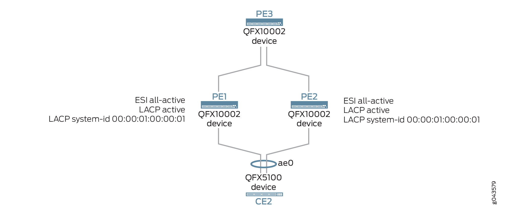
Topology
Figure 1 illustrates an EVPN VXLAN active-active multihoming network with LACP configured on the multi-homed CE and PE devices. Device CE1 is single-homed and is connected to remote PE1 and PE2 devices. Device CE2 is multi-homed to PE1 and PE2 devices.
Core isolation of Device PE1, for example, is handled as follows:
-
After PE2 and PE1 establish a BGP session, LACP sets the state of the CE-PE link to unblocking mode.
-
When there is a core failure, this can cause a null route at Device CE1.
To prevent this situation, the LAG interface that is facing Device CE2 is changed from the active state to the standby state by LACP.
-
LACP sends an out of-sync notification on the attached multihomed CE2 link to block traffic transmission between Device CE2 and Device PE1.
-
When the control plane recovers, Device PE2 is switched back from standby to active by LACP.
Configuration
- CLI Quick Configuration
- Configuring LACP for EVPN Active-Active Multihoming on PE3
- Configuring LACP for EVPN Active-Active Multihoming on PE1
- Configuring LACP for EVPN Active-Active Multihoming on PE2
- Configuring LACP for EVPN Active-Active Multihoming on CE2
CLI Quick Configuration
To quickly configure this example, copy the
following commands, paste them into a text file, remove any line breaks,
change any details necessary to match your network configuration,
copy and paste the commands into the CLI at the [edit] hierarchy
level, and then enter commit from configuration mode.
Device PE3
set interfaces xe-0/0/0 unit 0 family inet address 10.10.10.1/24
set interfaces xe-0/0/2 unit 0 family inet address 10.12.12.1/24
set interfaces xe-0/0/4 unit 0 family inet address 10.14.14.1/24
set interfaces xe-0/0/8 unit 0 family ethernet-switching interface-mode trunk
set interfaces xe-0/0/8 unit 0 family ethernet-switching vlan members all
set interfaces lo0 unit 0 family inet address 10.2.3.1/32 primary
set vlans v100 vlan-id 100
set vlans v200 vlan-id 200
set vlans v100 vxlan vni 100
set vlans v200 vxlan vni 200
set routing-options router-id 10.2.3.1
set routing-options autonomous-system 65011
set switch-options vtep-source-interface lo0.0
set switch-options route-distinguisher 10.2.3.1:1
set switch-options vrf-target target:1111:11
set protocols bgp group pe type internal
set protocols bgp group pe local-address 10.2.3.1
set protocols bgp group pe family evpn signaling
set protocols bgp group pe neighbor 10.2.3.3
set protocols bgp group pe neighbor 10.2.3.4
set protocols ospf area 0.0.0.0 interface xe-0/0/2
set protocols ospf area 0.0.0.0 interface lo0 passive
set protocols ospf area 0.0.0.0 interface xe-0/0/0
set protocols ospf area 0.0.0.0 interface xe-0/0/4
set protocols evpn encapsulation vxlan
set protocols evpn extended-vni-list all
Device PE1
set chassis aggregated-devices ethernet device-count 1
set interfaces xe-0/0/2 unit 0 family inet address 10.12.12.2/24
set interfaces xe-0/0/3 unit 0 family inet address 10.11.11.2/24
set interfaces xe-0/0/9 unit 0 family ethernet-switching interface-mode trunk
set interfaces xe-0/0/9 unit 0 family ethernet-switching vlan members v200
set interfaces ae0 unit 0 family ethernet-switching interface-mode trunk
set interfaces ae0 unit 0 family ethernet-switching vlan members all
set interfaces xe-0/0/55:0 ether-options 802.3ad ae0
set interfaces ae0 esi 00:03:03:03:03:03:03:03:03:03
set interfaces ae0 esi all-active
set interfaces ae0 aggregated-ether-options lacp active
set interfaces ae0 aggregated-ether-options lacp system-id 00:00:01:00:00:01
set interfaces lo0 unit 0 family inet address 10.2.3.3/32 primary
set vlans v100 vlan-id 100
set vlans v200 vlan-id 200
set vlans v100 vxlan vni 100
set vlans v200 vxlan vni 200
set routing-options router-id 10.2.3.3
set routing-options autonomous-system 65011
set switch-options vtep-source-interface lo0
set switch-options route-distinguisher 10.2.3.3:1
set switch-options vrf-target target:1111:11
set protocols bgp group pe type internal
set protocols bgp group pe local-address 10.2.3.3
set protocols bgp group pe family evpn signaling
set protocols bgp group pe neighbor 10.2.3.1
set protocols bgp group pe neighbor 10.2.3.4
set protocols ospf area 0.0.0.0 interface xe-0/0/2
set protocols ospf area 0.0.0.0 interface lo0.0 passive
set protocols ospf area 0.0.0.0 interface xe-0/0/3
set protocols evpn encapsulation vxlan
set protocols evpn extended-vni-list all
Device PE2
set chassis aggregated-devices ethernet device-count 1
set interfaces xe-0/0/2 unit 0 family inet address 10.14.14.2/24
set interfaces xe-0/0/5 unit 0 family ethernet-switching interface-mode trunk
set interfaces xe-0/0/5 unit 0 family ethernet-switching vlan members all
set interfaces ae0 unit 0 family ethernet-switching interface-mode trunk
set interfaces ae0 unit 0 family ethernet-switching vlan members all
set interfaces xe-0/0/55:0 ether-options 802.3ad ae0
set interfaces ae0 esi 00:03:03:03:03:03:03:03:03:03
set interfaces ae0 esi all-active
set interfaces ae0 aggregated-ether-options lacp active
set interfaces ae0 aggregated-ether-options lacp system-id 00:00:01:00:00:01
set interfaces lo0 unit 0 family inet address 10.2.3.4/32 primary
set vlans v100 vlan-id 100
set vlans v200 vlan-id 200
set vlans v100 vxlan vni 100
set vlans v200 vxlan vni 200
set routing-options router-id 10.2.3.4
set routing-options autonomous-system 65011
set switch-options vtep-source-interface lo0
set switch-options route-distinguisher 10.2.3.4:1
set switch-options vrf-target target:1111:11
set protocols bgp group pe type internal
set protocols bgp group pe local-address 10.2.3.4
set protocols bgp group pe family evpn signaling
set protocols bgp group pe neighbor 10.2.3.1
set protocols bgp group pe neighbor 10.2.3.2
set protocols bgp group pe neighbor 10.2.3.3
set protocols ospf area 0.0.0.0 interface xe-0/0/2
set protocols ospf area 0.0.0.0 interface lo0 passive
set protocols evpn encapsulation vxlan
set protocols evpn extended-vni-list all
Device CE2
set vlans v100 vlan-id 100
set vlans v200 vlan-id 200
set interfaces xe-0/0/3 unit 0 family ethernet-switching interface-mode trunk
set interfaces xe-0/0/3 unit 0 family ethernet-switching vlan members all
set interfaces xe-0/0/5 ether-options 802.3ad ae0
set interfaces xe-0/0/0 ether-options 802.3ad ae0
set interfaces ae0 unit 0 family ethernet-switching interface-mode trunk
set interfaces ae0 unit 0 family ethernet-switching vlan members all
set interfaces ae0 aggregated-ether-options lacp active
Configuring LACP for EVPN Active-Active Multihoming on PE3
Step-by-Step Procedure
The following example requires that you navigate various levels in the configuration hierarchy. For information about navigating the CLI, see Using the CLI Editor in Configuration Mode in the CLI User Guide.
To configure Device PE3:
-
Configure uplink interfaces towards PE1 and PE2 devices.
[edit interfaces]
user@CE1# set xe-0/0/0 unit 0 family inet address 10.10.10.1/24
user@CE1# set xe-0/0/2 unit 0 family inet address 12.12.12.1/24
user@CE1# set xe-0/0/4 unit 0 family inet address 14.14.14.1/24
-
Configure xe-0/0/8 as a Layer 2 interface.
[edit interfaces]
user@CE1# set xe-0/0/8 unit 0 family ethernet-switching interface-mode trunk
user@CE1# set xe-0/0/8 unit 0 family ethernet-switching vlan members all
-
Configure a loopback interface.
[edit interfaces]
user@CE1# set lo0 unit 0 family inet address 10.2.3.1/32 primary
-
Create VLANs v100 and v200.
[edit vlans]
user@CE1# set v100 vlan-id 100
user@CE1# set v200 vlan-id 200
-
Map VLANs v100 and v200 to VNIs 100 and 200.
[edit vlans]
user@CE1# set v100 vxlan vni 100
user@CE1# set v200 vxlan vni 200
-
Configure the router ID and autonomous system number.
[edit routing-options]
user@CE1# set router-id 10.2.3.1
user@CE1# set autonomous-system 65011
-
Specify the loopback interface as the source address for the VTEP tunnel.
[edit switch-options]
user@CE1# set vtep-source-interface lo0.0
-
Specify a route distinguisher to uniquely identify routes sent from this device.
[edit switch-options]
user@CE1# set route-distinguisher 10.2.3.1:1
-
Specify the global VRF export policy.
[edit switch-options]
user@CE1# set vrf-target target:1111:11
-
Configure an internal BGP group for PE3 to peer with PE1 and PE2.
[edit protocols]
user@CE1# set bgp group pe type internal
user@CE1# set bgp group pe local-address 10.2.3.1
user@CE1# set bgp group pe family evpn signaling
user@CE1# set bgp group pe neighbor 10.2.3.3
user@CE1# set bgp group pe neighbor 10.2.3.4
-
Configure an OSPF area.
[edit protocols]
user@CE1# set ospf area 0.0.0.0 interface xe-0/0/2
user@CE1# set ospf area 0.0.0.0 interface lo0 passive
user@CE1# set ospf area 0.0.0.0 interface xe-0/0/0
user@CE1# set ospf area 0.0.0.0 interface xe-0/0/4
-
Set VXLAN as the data plane encapsulation for EVPN.
[edit protocols]
user@CE1# set evpn encapsulation vxlan
-
Specify that all VNI(s) are advertised by EVPN.
[edit protocols]
user@CE1# set evpn extended-vni-list all
Results
From configuration mode, confirm your configuration
by entering the show chassis, show interfaces, show routing-options, show protocols, and show routing-instances commands. If the output does not display
the intended configuration, repeat the instructions in this example
to correct the configuration.
user@PE3# show interfaces
xe-0/0/0 {
    unit 0 {
        family inet {
            address 10.10.10.1/24;
        }
    }
}
xe-0/0/2 {
    unit 0 {
        family inet {
            address 10.10.6.1/30;
            address 10.12.12.1/24;
        }
    }
}
xe-0/0/4 {
    unit 0 {
        family inet {
            address 10.14.14.1/24;
        }
    }
}
xe-0/0/8 {
    unit 0 {
        family ethernet-switching {
            interface-mode trunk;
            vlan {
                members all;
            }
        }
    }
}
lo0 {
    unit 0 {
        family inet {
            address 10.10.0.1/32;
            address 10.2.3.1/32 {
                primary;
            }
        }
    }
}
user@PE3# show vlans
v100 {
    vlan-id 100;
    vxlan {
        vni 100;
    }
}
v200 {
    vlan-id 200;
    vxlan {
        vni 200;
    }
}
user@PE3# show routing-options
router-id 10.2.3.1;
autonomous-system 65011;
user@PE3# show switching-options
vtep-source-interface lo0;
route-distinguisher 10.2.3.1:1;
vrf-target target:1111:11;
user@PE3# show protocols bgp
group pe {
    type internal;
    local-address 10.2.3.1;
    family evpn {
        signaling;
    }
    neighbor 10.2.3.3;
    neighbor 10.2.3.4;
}
user@PE3# show protocols ospf
area 0.0.0.0 {
    interface lo0.0 {
        passive;
    }
    interface xe-0/0/2;
    interface xe-0/0/0;
    interface xe-0/0/4;
}
If you are done configuring the device, enter commit from configuration mode.
Configuring LACP for EVPN Active-Active Multihoming on PE1
Step-by-Step Procedure
The following example requires that you navigate various levels in the configuration hierarchy. For information about navigating the CLI, see Using the CLI Editor in Configuration Mode in the CLI User Guide.
To configure Device PE1:
-
Specify the number of aggregated Ethernet interfaces to be created on Device PE1.
[edit chassis]
user@PE1# set aggregated-devices ethernet device-count 1
-
Configure the interfaces that connect to the CE device.
[edit interfaces]
user@PE1# set xe-0/0/2 unit 0 family inet address 10.12.12.2/24
user@PE1# set xe-0/0/2 unit 0 family inet address 10.11.11.2/24
-
Configure xe-0/0/9 as a Layer 2 interface.
[edit interfaces]
user@PE1# set xe-0/0/9 unit 0 family ethernet-switching interface-mode trunk
user@PE1# set xe-0/0/9 unit 0 family ethernet-switching vlan members v200
-
Configure ae0 as a Layer 2 interface.
[edit interfaces]
user@PE1# set ae0 unit 0 family ethernet-switching interface-mode trunk
user@PE1# set ae0 unit 0 family ethernet-switching vlan members all
-
Configure the interface towards the multihomed device, CE2.
Use the same ESI value on all PE devices where the CE2 is multihomed.
[edit interfaces]
user@PE1# set xe-0/0/55:0 ether-options 802.3ad ae0
user@PE1# set ae0 esi 00:03:03:03:03:03:03:03:03:03
user@PE1# set ae0 esi all-active
-
Configure LACP on the ae0.
Use the same system ID value on all PE devices where the CE2 is multihomed.
[edit interfaces]
user@PE1# set ae0 aggregated-ether-options lacp active
user@PE1# set ae0 aggregated-ether-options lacp system-id 00:00:01:00:00:01
-
Configure a loopback interface.
[edit interfaces]
user@PE1# set lo0 unit 0 family inet address 10.2.3.3/32 primary
-
Create VLANs v100 and v200.
[edit vlans]
user@PE1# set v100 vlan-id 100
user@PE1# set v200 vlan-id 200
-
Map VLANs v100 and v200 to VNIs 100 and 200.
[edit vlans]
user@PE1# set v100 vxlan vni 100
user@PE1# set v200 vxlan vni 200
-
Configure a router ID and autonomous system number.
[edit routing-options]
user@PE1# set router-id 10.2.3.3
user@PE1# set autonomous-system 65011
-
Specify the loopback interface as the source address for the VTEP tunnel.
[edit switch-options]
user@PE1# set vtep-source-interface lo0.0
-
Specify a route distinguisher to uniquely identify routes sent from this device.
[edit switch-options]
user@PE1# set route-distinguisher 10.2.3.3:1
-
Specify the global VRF export policy.
[edit switch-options]
user@PE1# set vrf-target target:1111:11
-
Configure an internal BGP group for PE3 to peer with PE1 and PE2.
[edit protocols]
user@PE1# set bgp group pe type internal
user@PE1# set bgp group pe local-address 10.2.3.3
user@PE1# set bgp group pe family evpn signaling
user@PE1# set bgp group pe neighbor 10.2.3.1
user@PE1# set bgp group pe neighbor 10.2.3.4
-
Configure an OSPF area.
[edit protocols]
user@PE1# set ospf area 0.0.0.0 interface xe-0/0/2
user@PE1# set ospf area 0.0.0.0 interface lo0 passive
user@PE1# set ospf area 0.0.0.0 interface xe-0/0/3
-
Set VXLAN as the data plane encapsulation for EVPN.
[edit protocols]
user@PE1# set evpn encapsulation vxlan
-
Specify that all VNI(s) are advertised by EVPN.
[edit protocols]
user@PE1# set evpn extended-vni-list all
Results
From configuration mode, confirm your configuration
by entering the show chassis, show interfaces, show routing-options, show protocols, and show routing-instances commands. If the output does not display
the intended configuration, repeat the instructions in this example
to correct the configuration.
user@PE1# show chassis
aggregated-devices {
    ethernet {
        device-count 1;
    }
}
user@PE1# show interfaces
xe-0/0/2 {
    unit 0 {
        family inet {
            address 10.10.6.1/30;
            address 10.12.12.1/24;
            address 10.12.12.2/24;
        }
    }
}
xe-0/0/3 {
    unit 0 {
        family inet {
            address 10.11.11.2/24;
        }
    }
}
xe-0/0/9 {
    unit 0 {
        family ethernet-switching {
            interface-mode trunk;
            vlan {
                members v200;
            }
        }
    }
}
xe-0/0/55:0 {
    ether-options {
        802.3ad ae0;
    }
}
ae0 {
    esi {
        00:03:03:03:03:03:03:03:03:03;
        all-active;
    }
    aggregated-ether-options {
        lacp {
            active;
            system-id 00:00:01:00:00:01;
        }
    }
    unit 0 {
        family ethernet-switching {
            interface-mode trunk;
            vlan {
                members all;
            }
        }
    }
}
user@PE1# show vlans
v100 {
    vlan-id 100;

    vxlan {
        vni 100;
    }
}
v200 {
    vlan-id 200;

    vxlan {
        vni 200;
    }
}
user@PE1# show routing-options
router-id 10.2.3.3;
autonomous-system 65011;
user@PE1# show switching-options
vtep-source-interface lo0;
route-distinguisher 10.2.3.3:1;
vrf-target target:1111:11;
user@PE1# show protocols bgp
group pe {
    type internal;
    local-address 10.2.3.3;
    family evpn {
        signaling;
    }
    neighbor 10.2.3.3;
    neighbor 10.2.3.4;
    neighbor 10.2.3.1;
}
user@PE1# show protocols ospf
area 0.0.0.0 {
    interface lo0 {
        passive;
    }
    interface xe-0/0/2;
    interface xe-0/0/3;
}
user@PE1# show protocols evpn
encapsulation vxlan;
extended-vni-list all;
If you are done configuring the device, enter commit from configuration mode.
Configuring LACP for EVPN Active-Active Multihoming on PE2
Step-by-Step Procedure
The following example requires that you navigate various levels in the configuration hierarchy. For information about navigating the CLI, see Using the CLI Editor in Configuration Mode in the CLI User Guide.
To configure Device PE2:
-
Specify the number of aggregated Ethernet interfaces to be created on Device PE1.
[edit chassis]
user@PE2# set aggregated-devices ethernet device-count 1
-
Configure the interface that connects to the CE device.
[edit interfaces]
user@PE2# set xe-0/0/2 unit 0 family inet address 10.14.14.2/24
-
Configure xe-0/0/5 as a Layer 2 interface.
[edit interfaces]
user@PE2# set xe-0/0/5 unit 0 family ethernet-switching interface-mode trunk
user@PE2# set xe-0/0/5 unit 0 family ethernet-switching vlan members v200
-
Configure ae0 as a Layer 2 interface.
[edit interfaces]
user@PE2# set ae0 unit 0 family ethernet-switching interface-mode trunk
user@PE2# set ae0 unit 0 family ethernet-switching vlan members all
-
Configure the interface towards the multihomed device, CE2.
Use the same ESI value on all PE devices where the CE2 is multihomed.
[edit interfaces]
user@PE2# set xe-0/0/55:0 ether-options 802.3ad ae0
user@PE2# set ae0 esi 00:03:03:03:03:03:03:03:03:03
user@PE2# set ae0 esi all-active
-
Configure LACP on the ae0.
Use the same system ID value on all PE devices where the CE2 is multihomed.
[edit interfaces]
user@PE2# set ae0 aggregated-ether-options lacp active
user@PE2# set ae0 aggregated-ether-options lacp system-id 00:00:01:00:00:01
-
Configure a loopback interface.
[edit interfaces]
user@PE2# set lo0 unit 0 family inet address 10.2.3.4/32 primary
-
Create VLANs v100 and v200.
[edit vlans]
user@PE2# set v100 vlan-id 100
user@PE2# set v200 vlan-id 200
-
Map VLANs v100 and v200 to VNIs 100 and 200.
[edit vlans]
user@PE2# set v100 vxlan vni 100
user@PE2# set v200 vxlan vni 200
-
Configure a router ID and autonomous system number.
[edit routing-options]
user@PE2# set router-id 10.2.3.4
user@PE2# set autonomous-system 65011
-
Specify the loopback interface as the source address for the VTEP tunnel.
[edit switch-options]
user@PE2# set vtep-source-interface lo0.0
-
Specify a route distinguisher to uniquely identify routes sent from this device.
[edit switch-options]
user@PE2# set route-distinguisher 10.2.3.4:1
-
Specify the global VRF export policy.
[edit switch-options]
user@PE2# set vrf-target target:1111:11
-
Configure an internal BGP group for PE3 to peer with PE1 and PE2.
[edit protocols]
user@PE2# set bgp group pe type internal
user@PE2# set bgp group pe local-address 10.2.3.4
user@PE2# set bgp group pe family evpn signaling
user@PE2# set bgp group pe neighbor 10.2.3.1
user@PE2# set bgp group pe neighbor 10.2.3.2
user@PE2# set bgp group pe neighbor 10.2.3.3
-
Configure an OSPF area.
[edit protocols]
user@PE2# set ospf area 0.0.0.0 interface xe-0/0/2
user@PE2# set ospf area 0.0.0.0 interface lo0 passive
-
Set VXLAN as the data plane encapsulation for EVPN.
[edit protocols]
user@PE2# set evpn encapsulation vxlan
-
Specify that all VNI(s) are advertised by EVPN.
[edit protocols]
user@PE2# set evpn extended-vni-list all
Results
From configuration mode, confirm your configuration
by entering the show chassis, show interfaces, show routing-options, show protocols, and show routing-instances commands. If the output does not display
the intended configuration, repeat the instructions in this example
to correct the configuration.
user@PE2# show chassis
aggregated-devices {
    ethernet {
        device-count 1;
    }
}
user@PE2# show interfaces
xe-0/0/2 {
    unit 0 {
        family inet {
            address 10.14.14.2/24;
        }
    }
}
xe-0/0/5 {
    unit 0 {
        family ethernet-switching {
            interface-mode trunk;
            vlan {
                members all;
            }
        }
    }
}
xe-0/0/55:0 {
    ether-options {
        802.3ad ae0;
    }
}
ae0 {
    esi {
        00:03:03:03:03:03:03:03:03:03;
        all-active;
    }
    aggregated-ether-options {
        lacp {
            active;
            system-id 00:00:01:00:00:01;
        }
    }
    unit 0 {
        family ethernet-switching {
            interface-mode trunk;
            vlan {
                members all;
            }
        }
    }
}
lo0 {
    unit 0 {
        family inet {
            address 10.2.3.4/32 {
                primary;
            }
        }
    }
}
user@PE2# show vlans
v100 {
    vlan-id 100;

    vxlan {
        vni 100;
    }
}
v200 {
    vlan-id 200;

    vxlan {
        vni 200;
    }
}
user@PE2# show routing-options
router-id 10.2.3.4;
autonomous-system 65011;
user@PE2# show switching-options
vtep-source-interface lo0;
route-distinguisher 10.2.3.4:1;
vrf-target target:1111:11;
user@PE2# show protocols bgp
group pe {
    type internal;
    local-address 10.2.3.4;
    family evpn {
        signaling;
    }
    neighbor 10.2.3.3;
    neighbor 10.2.3.4;
    neighbor 10.2.3.1;
}
user@PE2# show protocols ospf
area 0.0.0.0 {
    interface lo0 {
        passive;
    }
    interface xe-0/0/2;
}
user@PE2# show protocols evpn
encapsulation vxlan;
extended-vni-list all;
If you are done configuring the device, enter commit from configuration mode.
Configuring LACP for EVPN Active-Active Multihoming on CE2
Step-by-Step Procedure
The following example requires that you navigate various levels in the configuration hierarchy. For information about navigating the CLI, see Using the CLI Editor in Configuration Mode in the CLI User Guide.
To configure Device CE1:
-
Configure VLANs v100 and v200.
[edit vlans]
user@CE2# set v100 vlan-id 100
user@CE2# set v200 vlan-id 200
-
Configure xe-0/0/3 as a Layer 2 interface.
[edit interfaces]
user@CE2# set xe-0/0/3 unit 0 family ethernet-switching interface-mode trunk
user@CE2# set xe-0/0/3 unit 0 family ethernet-switching vlan members all
-
Add member interfaces to ae0.
[edit interfaces]
user@CE2# set xe-0/0/0 ether-options 802.3ad ae0
user@CE2# set xe-0/0/5 ether-options 802.3ad ae0
-
Configure ae0 as a Layer 2 interface.
[edit interfaces]
user@CE2# set ae0 unit 0 family ethernet-switching interface-mode trunk
user@CE2# set ae0 unit 0 family ethernet-switching vlan members all
-
Configure LACP as active for ae0.
[edit interfaces]
user@CE2# set ae0 aggregated-ether-options lacp active
Results
From configuration mode, confirm your configuration
by entering the show chassis, show interfaces, show routing-options, show protocols, and show routing-instances commands. If the output does not display
the intended configuration, repeat the instructions in this example
to correct the configuration.
user@CE2# show interfaces
xe-0/0/0 {
    ether-options {
        802.3ad ae0;
    }
}
xe-0/0/3 {
    unit 0 {
        family ethernet-switching {
            interface-mode trunk;
            vlan {
                members all;
            }
        }
    }
}
user@CE2# show vlans
v100 {
    vlan-id 100;
    vxlan {
        vni 100;
    }
}
v200 {
    vlan-id 200;
    vxlan {
        vni 200;
    }
}
If you are done configuring the device, enter commit from configuration mode.
Verification
Confirm that the configuration is working properly.
Verifying LACP Interface Status of PE1
Purpose
Verify the LACP interface state on Device PE1.
Action
From operational mode, run the show lacp interfaces command.
user@PE1> show lacp interfaces
Aggregated interface: ae0
    LACP state:       Role   Exp   Def  Dist  Col  Syn  Aggr  Timeout  Activity
      xe-0/0/55:0     Actor   No    No   Yes  Yes  Yes   Yes     Fast    Active
      xe-0/0/55:0     Partner No    No   Yes  Yes  Yes   Yes     Fast    Active
    LACP protocol:    Receive State  Transmit State      Mux State
      xe-0/0/55:0     Current        Fast periodic       Collecting distributing
Meaning
The LACP LAG interface state is active.
In our example all links and protocols are operational. When all BGP sessions used for Ethernet VPN (EVPN) are down the core isolation feature activates. In this state the leaf brings down LACP to prevent the attached device from sending data. On the leaf the LACP interface status is updated to show core isolation down (CDN). To demonstrate we deactivated BGP on the leaf. The LACP interface status is updated to show core isolation is in effect:
user@PE1> show lacp interfaces
Aggregated interface: ae0
    LACP state:         Role   Exp   Def  Dist  Col  Syn  Aggr  Timeout  Activity
      xe-0/0/55:0 CDN Actor   No    No    No   No   No   Yes     Fast    Active
      xe-0/0/55:0 CDN Partner No    No    No   No   Yes   Yes    Fast    Active
    LACP protocol:      Receive State  Transmit State          Mux State
      xe-0/0/55:0       Current         Fast periodic          Waiting
Verifying LACP Interface Status of PE2
Purpose
Verify the LACP interface state on Device PE2.
Action
From operational mode, run the show lacp interfaces command.
user@PE2> show lacp interfaces
Aggregated interface: ae0
    LACP state:       Role   Exp   Def  Dist  Col  Syn  Aggr  Timeout  Activity
      xe-0/0/55:0     Actor   No    No   Yes  Yes  Yes   Yes     Fast    Acttive
      xe-0/0/55:0     Partner No    No   Yes  Yes  Yes   Yes     Fast    Active
    LACP protocol:    Receive State  Transmit State          Mux State
      xe-0/0/55:0     Current        Fast periodic           Collecting distributing
Meaning
The LACP LAG interface state is active.