Understanding When to Disable EVPN-VXLAN Core Isolation
By default, spine and leaf devices in an EVPN network implement the core isolation feature. If one of these devices loses all of its EVPN BGP peering sessions, the core isolation feature, working in conjunction with Link Aggregation Control Protocol (LACP), automatically brings down all Layer 2 Ethernet Segment Identifier (ESI) link aggregation group (LAG) interfaces on the device.
In some situations, the core isolation feature produces a favorable outcome. However, in other situations, the feature produces an undesired outcome, which you can prevent by disabling the feature. The next sections describe an example situation in each case.
Use Case 1: Example of When to Use the Core Isolation Feature
Figure 1 displays a topology in which two QFX10000 switches act as spine devices that form an EVPN-VXLAN core. In this topology, six QFX5110 switches that act as leaf devices are multihomed in active-active mode to the spine devices, and in turn, each server is multihomed through ESI-LAG interfaces to two leaf devices.
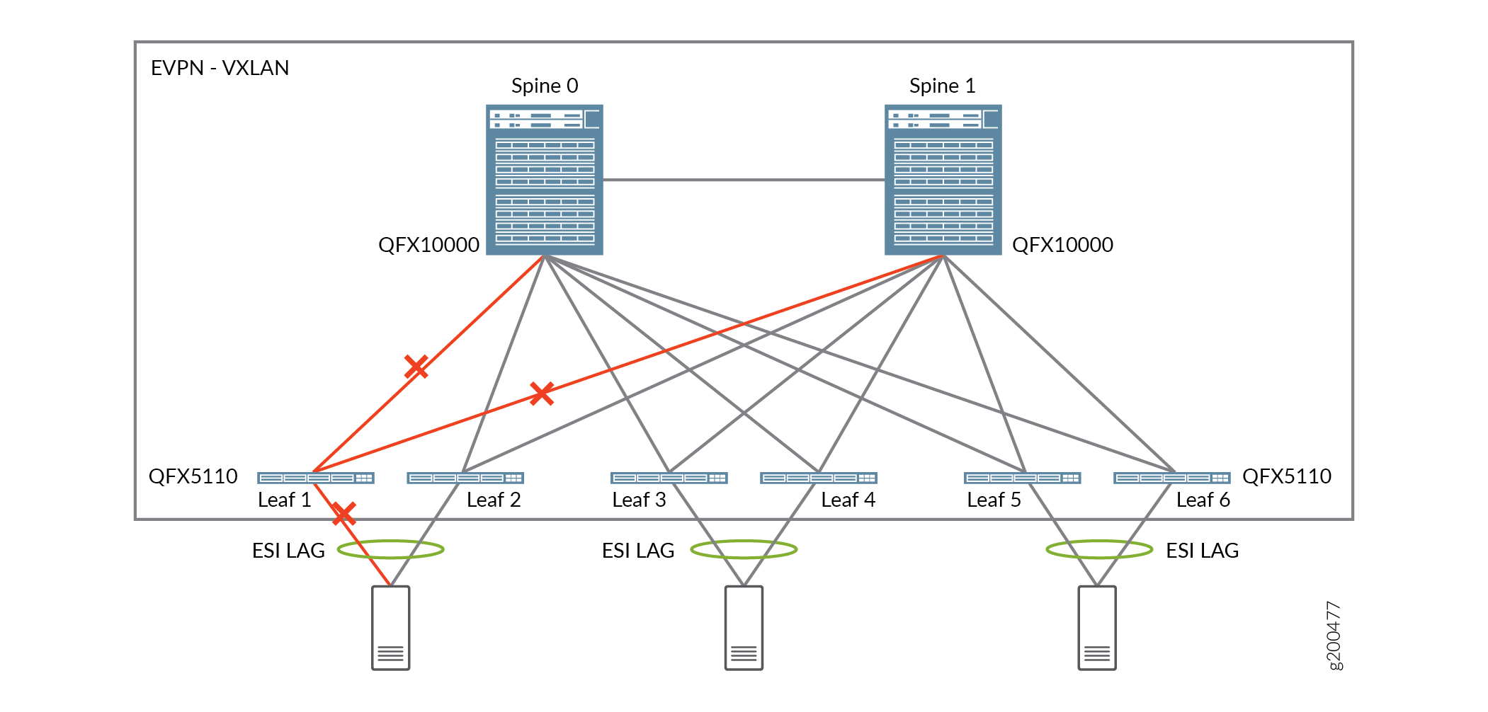
If the links between Leaf 1 and the two spine devices go down, the BGP peering sessions established over the links also go down. With the core isolation feature enabled by default, LACP sets the server-facing interface on Leaf 1 to standby mode, which blocks all traffic from the server. In this situation, the default implementation of the core isolation feature provides the following benefits:
-
With the links from Leaf 1 to both spine devices down, it does not make sense for the server to continue forwarding traffic to Leaf 1.
-
Traffic from the server is diverted to Leaf 2 until the links between Leaf 1 and the two spine devices are up again.
Use Case 2: Example of When to Disable the Core Isolation Feature
The topology shown in Figure 2 is migrating from multichassis link aggregation (MC-LAG) and Virtual Chassis environments to an EVPN-VXLAN environment. In this topology, the only EVPN-VXLAN components are two QFX10000 switches that act as spine devices. The QFX5110 switches that act as leaf (MC-LAG and Virtual Chassis) devices are multihomed in active-active mode through ESI-LAG interfaces to the spine devices.
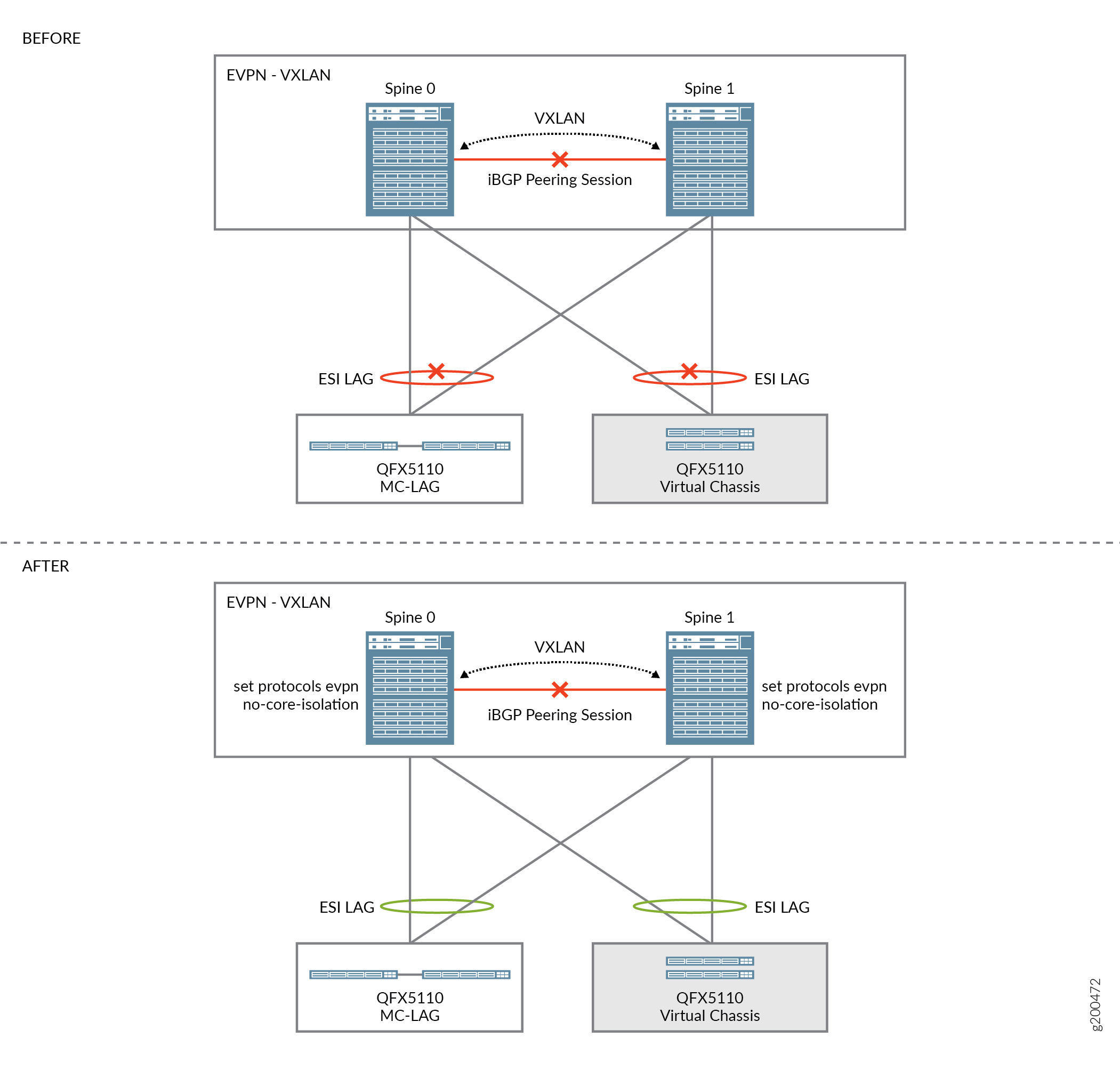
If the link between Spine 0 and Spine 1 goes down, the last established BGP peering session also goes down. With the core isolation feature enabled by default, LACP sets the leaf-facing interfaces on Spines 0 and 1 to standby mode, which causes data traffic to and from both leaf devices to be dropped. With the core isolation feature implemented at the leaf device level, traffic within the data center would essentially be halted, which is an undesired outcome.
In cases like this, you can set no-core-isolation at the [edit protocols
evpn] configuration hierarchy level on each spine device to disable the
core isolation feature. See the AFTER illustration in Figure 2. This statement is available only at the global level, so it applies to either
all EVPN routing instances or the default switch instance on devices that don't have
multiple routing instances.
Change History Table
Feature support is determined by the platform and release you are using. Use Feature Explorer to determine if a feature is supported on your platform.
no-core-isolation configuration statement at the
[edit protocols evpn] hierarchy level on spine device s in
the fabric to disable the core isolation feature.