ON THIS PAGE
Example: Configuring EVPN E-Tree Service
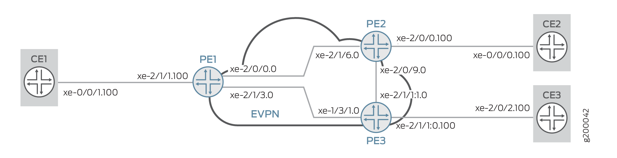
This example shows how to configure the Ethernet VPN (EVPN) Ethernet-Tree (E-Tree) service.
Requirements
This example uses the following hardware and software components:
-
Three MX Series 5G Universal Routing Platforms configured as provider edge (PE) routers.
-
Three customer edge (CE) routers, each connected to the PE routers.
-
Junos OS Release 17.2 or later running on all the PE routers.
Before you begin:
-
Configure the device interfaces.
-
Configure an IGP, such as OSPF, on all the devices.
-
Establish a BGP session between the PE devices.
-
Configure MPLS and LDP on the PE devices.
Overview
You can use the EVPN E-Tree feature to create a rooted-multipoint service supported with EVPN-MPLS in the core, as defined by the Metro Ethernet Forum (MEF) in RFC 8317. In an EVPN E-Tree service, you categorize interfaces as either root or leaf interfaces in a routing instance. You also define each customer edge (CE) device as a root or a leaf device. The EVPN E-Tree service follows these forwarding rules:
-
A leaf can send or receive traffic only from a root.
-
A root can send traffic to another root or any leaf.
Leaf and root CE devices can be single-homed or multihomed to the provider edge (PE) devices in the network.
Platform-Specific EVPN E-Tree Behavior
Use the following table to review platform-specific behaviors for your platforms.
|
Platform |
Difference |
|---|---|
|
ACX5448 Routers |
When you enable EVPN E-Tree on ACX5448 routers, you must also
set the system profile option
|
Configuration
CLI Quick Configuration
To quickly configure this example, copy the following commands, paste them into a text file, remove any line breaks, change any details necessary to match your network configuration, copy and paste the commands into the CLI at the [edit] hierarchy level, and then enter commit from configuration mode.
When you want to change the etree-ac-role from
leaf to root or vice versa, use the
following procedure.
-
Deactivate the interface
unitconfiguration. -
Change the
etree-ac-roleoption under the deactivatedunitconfiguration. -
Reactivate the updated interface
unitconfiguration.
Deactivating the interface unit before changing the
etree-ac-role option ensures that the system applies
the role change correctly to all the E-Tree components.
CE1
set  interfaces xe-0/0/1 vlan-tagging
>set  interfaces xe-0/0/1 unit 100 vlan-id 100
>set  interfaces xe-0/0/1 unit 100 family inet address 10.100.0.1/24
PE1
>set interfaces xe-2/0/0 unit 0 family inet address 10.0.0.1/30
>set interfaces xe-2/0/0 unit 0 family mpls
>set interfaces xe-2/1/3 unit 0 family inet address 10.0.0.5/30
>set interfaces xe-2/1/3 unit 0 family mpls
>set interfaces lo0 unit 0 family inet address 10.255.0.1/32 primary
>set interfaces lo0 unit 0 family inet address 10.255.0.1/32 preferred
>set interfaces xe-2/1/1 flexible-vlan-tagging
>set interfaces xe-2/1/1 encapsulation flexible-ethernet-services
>set interfaces xe-2/1/1 unit 100 encapsulation vlan-bridge
>set interfaces xe-2/1/1 unit 100 vlan-id 100
>set interfaces xe-2/1/1 unit 100 etree-ac-role root
>set routing-options router-id 10.255.0.1
>set routing-options autonomous-system 65000
>set protocols mpls interface all
>set protocols mpls interface fxp0.0 disable
>set protocols bgp group evpn local-address 10.255.0.1
>set protocols bgp group evpn family evpn signaling
>set protocols bgp group evpn peer-as 65000
>set protocols bgp group evpn local-as 65000
>set protocols bgp group evpn neighbor 10.255.0.2
>set protocols bgp group evpn neighbor 10.255.0.3
>set protocols ospf area 0.0.0.0 interface all
>set protocols ospf area 0.0.0.0 interface fxp0.0 disable
>set protocols ldp interface all
>set protocols ldp interface fxp0.0 disable
>set routing-instances evpna instance-type evpn
>set routing-instances evpna vlan-id 100
>set routing-instances evpna interface xe-2/1/1.100
>set routing-instances evpna route-distinguisher 10.255.0.1:100
>set routing-instances evpna vrf-target target:65000:100
>set routing-instances evpna protocols evpn interface xe-2/1/1.100
>set routing-instances evpna protocols evpn evpn-etree
PE2
>set interfaces xe-2/1/6 unit 0 family inet address 10.0.0.2/30
>set interfaces xe-2/1/6 unit 0 family mpls
>set interfaces xe-2/0/9 unit 0 family inet address 10.0.0.9/30
>set interfaces xe-2/0/9 unit 0 family mpls
>set interfaces lo0 unit 0 family inet address 10.255.0.2/32 primary
>set interfaces lo0 unit 0 family inet address 10.255.0.2/32 preferred
>set interfaces xe-2/0/0 flexible-vlan-tagging
>set interfaces xe-2/0/0 encapsulation flexible-ethernet-services
>set interfaces xe-2/0/0 unit 100 encapsulation vlan-bridge
>set interfaces xe-2/0/0 unit 100 vlan-id 100
>set interfaces xe-2/0/0 unit 100 etree-ac-role leaf
>set routing-options router-id 10.255.0.2
>set routing-options autonomous-system 65000
>set protocols mpls interface all
>set protocols mpls interface fxp0.0 disable
>set protocols bgp group evpn local-address 10.255.0.2
>set protocols bgp group evpn family evpn signaling
>set protocols bgp group evpn peer-as 65000
>set protocols bgp group evpn local-as 65000
>set protocols bgp group evpn neighbor 10.255.0.1
>set protocols bgp group evpn neighbor 10.255.0.3
>set protocols ospf area 0.0.0.0 interface all
>set protocols ospf area 0.0.0.0 interface fxp0.0 disable
>set protocols ldp interface all
>set protocols ldp interface fxp0.0 disable
>set routing-instances evpna instance-type evpn
>set routing-instances evpna vlan-id 100
>set routing-instances evpna interface xe-2/0/0.100
>set routing-instances evpna route-distinguisher 10.255.0.2:100
>set routing-instances evpna vrf-target target:65000:100
>set routing-instances evpna protocols evpn interface xe-2/0/0.100
>set routing-instances evpna protocols evpn evpn-etree
PE3
>set  interfaces xe-1/3/1 unit 0 family inet address 10.0.0.6/30
>set  interfaces xe-1/3/1 unit 0 family mpls
>set  interfaces xe-2/1/1:1 unit 0 family inet address 10.0.0.10/30
>set  interfaces xe-2/1/1:1 unit 0 family mpls
>set  interfaces lo0 unit 0 family inet address 10.255.0.3/32 primary
>set  interfaces lo0 unit 0 family inet address 10.255.0.3/32 preferred
>set  interfaces xe-2/1/1:0 flexible-vlan-tagging
>set  interfaces xe-2/1/1:0 encapsulation flexible-ethernet-services
>set  interfaces xe-2/1/1:0 unit 100 encapsulation vlan-bridge
>set  interfaces xe-2/1/1:0 unit 100 vlan-id 100
>set  interfaces xe-2/1/1:0 unit 100 etree-ac-role leaf
>set  routing-options router-id 10.255.0.3
>set  routing-options autonomous-system 65000
>set  protocols mpls interface all
>set  protocols mpls interface fxp0.0 disable
>set  protocols bgp group evpn local-address 10.255.0.3
>set  protocols bgp group evpn family evpn signaling
>set  protocols bgp group evpn peer-as 65000
>set  protocols bgp group evpn local-as 65000
>set  protocols bgp group evpn neighbor 10.255.0.1
>set  protocols bgp group evpn neighbor 10.255.0.2
>set  protocols ospf area 0.0.0.0 interface all
>set  protocols ospf area 0.0.0.0 interface fxp0.0 disable
>set  protocols ldp interface all
>set  protocols ldp interface fxp0.0 disable
>set  routing-instances evpna instance-type evpn
>set  routing-instances evpna vlan-id 100
>set  routing-instances evpna interface xe-2/1/1:0.100
>set  routing-instances evpna route-distinguisher 10.255.0.3:100
>set  routing-instances evpna vrf-target target:65000:100
>set  routing-instances evpna protocols evpn interface xe-2/1/1:0.100
>set  routing-instances evpna protocols evpn evpn-etree
CE2
>set interfaces xe-0/0/0 vlan-tagging
>set interfaces xe-0/0/0 unit 100 vlan-id 100
>set interfaces xe-0/0/0 unit 100 family inet address 10.100.0.2/24
CE3
>set interfaces xe-2/0/2 vlan-tagging
>set interfaces xe-2/0/2 unit 100 vlan-id 100
>set interfaces xe-2/0/2 unit 100 family inet address 10.100.0.3/24
Procedure
Step-by-Step Procedure
The following example requires you to navigate various levels in the configuration hierarchy. For information about navigating the CLI, see Using the CLI Editor in Configuration Mode.
To configure Router PE1:
Repeat this procedure for Routers PE2 and PE3, after modifying the appropriate interface names, addresses, and other parameters.
-
Configure Router PE1 interfaces.
[edit interfaces]user@PE1#set xe-2/0/0 unit 0 family inet address 10.0.0.1/30 user@PE1#set xe-2/0/0 unit 0 family mpls user@PE1#set xe-2/1/3 unit 0 family inet address 10.0.0.5/30 user@PE1#set xe-2/1/3 unit 0 family mpls user@PE1#set lo0 unit 0 family inet address 10.255.0.1/32 primary user@PE1#set lo0 unit 0 family inet address 10.255.0.1/32 preferred user@PE1#set xe-2/1/1 flexible-vlan-tagging user@PE1#set xe-2/1/1 encapsulation flexible-ethernet-services user@PE1#set xe-2/1/1 unit 100 encapsulation vlan-bridge user@PE1#set xe-2/1/1 unit 100 vlan-id 100 -
Assign the interface as leaf or root.
user@PE1#
[edit interfaces]set xe-2/1/1 unit 100 etree-ac-role root -
Set the router ID and autonomous system number for Router PE1.
[edit routing-options]user@PE1#set routing-options router-id 10.255.0.1 user@PE1#set routing-options autonomous-system 65000 -
Enable LDP on all the interfaces of Router PE1, excluding the management interface.
[edit protocols]user@PE1# set ldp interface all user@PE1# set ldp interface fxp0.0 disable -
Assign local and neighbor addresses to the BGP group for Router PE1 to peer with Routers PE2 and PE3.
[edit protocols]user@PE1#set bgp group evpn local-address 10.255.0.1 user@PE1#set bgp group evpn neighbor 10.255.0.2 user@PE1#set bgp group evpn neighbor 10.255.0.3 -
Set up the local and peer autonomous systems.
user@PE1#set  protocols bgp group evpn peer-as 65000
user@PE1#set  protocols bgp group evpn local-as 65000
-
Include the EVPN signaling Network Layer Reachability Information (NLRI) to the bgp BGP group.
[edit protocols]user@PE1#set bgp group evpn family evpn signaling -
Configure OSPF on all the interfaces of Router PE1, excluding the management interface.
[edit protocols]user@PE1#set ospf area 0.0.0.0 interface all user@PE1#set ospf area 0.0.0.0 interface fxp0.0 disable -
Configure MPLS on all the interfaces of Router PE1, excluding the management interface.
[edit protocols]user@PE1#set mpls interface all user@PE1#set mpls interface fxp0.0 disable -
Configure the EVPN routing instance.
[edit routing-instances]
user@PE1# set evpna instance-type evpn
-
Set the VLAN identifier for the bridging domain in the evpna routing instance.
[edit routing-instances]
user@PE1# set evpna vlan-id 100
-
Configure the interface name for the evpna routing instance.
[edit routing-instances]
user@PE1#set evpna interface xe-2/1/1.100
-
Configure the route distinguisher for the evpna routing instance.
[edit routing-instances]
user@PE1#set evpna route-distinguisher 10.255.0.1:100
-
Assign the interface name that connects the PE1 site to the VPN.
[edit routing-instances]
user@PE1#set evpna protocols evpn interface xe-2/1/1.100
-
Configure Ethernet VPN E-Tree service on PE1.
[edit routing-instances]
user@PE1#set evpna protocols evpn evpn-etree
-
Configure the VPN routing and forwarding (VRF) target community for the evpna routing instance.
[edit routing-instances]
user@PE1#set evpna vrf-target target:65000:100
Results
From configuration mode, confirm your configuration
by entering the show interfaces, show routing-options, and show routing-instances commands. If the output does
not display the intended configuration, repeat the instructions in
this example to correct the configuration.
user@PE1 show interfaces
xe-2/0/0 {
    unit 0 {
        family inet {
            address 10.0.0.1/30;
        }
        family mpls;
    }
}
xe-2/1/3 {
    unit 0 {
        family inet {
            address 10.0.0.5/30;
        }
        family mpls;
    }
}
lo0 {
    unit 0 {
        family inet {
            address 10.255.0.1/32 {
                primary;
                preferred;
            }
        }
    }
}
xe-2/1/1 {
    flexible-vlan-tagging;
    encapsulation flexible-ethernet-services;
    unit 100 {
        encapsulation vlan-bridge;
        vlan-id 100;
        etree-ac-role root;
    }
}
user@PE1 show routing-options
router-id 10.255.0.1;
autonomous-system 65000;
user@PE1 show protocols
mpls {
    interface all;
    interface fxp0.0 {
        disable;
    }
}
bgp {
    group evpn {
        local-address 10.255.0.1;
        family evpn {
            signaling;
        }
        peer-as 65000;
        local-as 65000;
        neighbor 10.255.0.2;
        neighbor 10.255.0.3;
    }
}
ospf {
    area 0.0.0.0 {
        interface all;
        interface fxp0.0 {
            disable;
        }
    }
}
ldp {
    interface all;
    interface fxp0.0 {
        disable;
    }
}
user@PE1 #show routing-instances
evpna {
    instance-type evpn;
    vlan-id 100;
    interface xe-2/1/1.100;
    route-distinguisher 10.255.0.1:100;
    vrf-target target:65000:100;
    protocols {
        evpn {
            interface xe-2/1/1.100;
            evpn-etree;
        }
    }
}
Verification
Confirm that the configuration is working properly.
- Verifying the EVPN Instance Status
- Verifying local and remote MAC property
- Verifying EVPN E-Tree Instances property
- Verifying traffic between leaf and root
- Verifying traffic flow between leaf and leaf is not allowed
Verifying the EVPN Instance Status
Purpose
Verify the EVPN routing instances and their status.
Action
From operational mode, run the show evpn instance
extensive command.
user@PE1>show evpn instance extensive
Instance: __default_evpn__
  Route Distinguisher: 10.255.0.1:0
  Number of bridge domains: 0
  Number of neighbors: 0

Instance: evpna
  Route Distinguisher: 10.255.0.1:100
  VLAN ID: 100
  Per-instance MAC route label: 16
  Etree Leaf label: 20
  MAC database status                     Local  Remote
    MAC advertisements:                       1       1
    MAC+IP advertisements:                    0       0
    Default gateway MAC advertisements:       0       0
  Number of local interfaces: 1 (1 up)
    Interface name  ESI                            Mode             Status     AC-Role
    xe-2/1/1.100    00:00:00:00:00:00:00:00:00:00  single-homed     Up         Root
  Number of IRB interfaces: 0 (0 up)
  Number of bridge domains: 1
    VLAN  Domain ID   Intfs / up    IRB intf   Mode             MAC sync  IM route label  SG sync  IM core nexthop
    100                  1    1                Extended         Enabled   30              Disabled
  Number of neighbors: 2
    Address               MAC    MAC+IP        AD        IM        ES Leaf-label
    10.255.0.2              0         0         1         1         0        20
    10.255.0.3              1         0         1         1         0        20
  Number of ethernet segments: 0
Meaning
The output provides the following information:
-
List of EVPN and virtual switch routing instances
-
Mode of operation of each interface
-
Neighbors of each routing instance
-
Number of different routes received from each neighbor
-
Number of Ethernet segments on each routing instance
-
VLAN ID and MAC labels for each routing instance
Verifying local and remote MAC property
Purpose
Verify EVPN MAC table information.
Action
From operational mode, run the show evpn mac-table command.
user@PE1>show evpn mac-table
MAC flags       (S -static MAC, D -dynamic MAC, L -locally learned, C -Control MAC
    O -OVSDB MAC, SE -Statistics enabled, NM -Non configured MAC, R -Remote PE MAC, P -Pinned MAC)

Routing instance : evpn_100
 Bridging domain : __evpn_100__, VLAN : 100
   MAC                 MAC      Logical          NH     MAC
   address             flags    interface        Index  property
   00:1d:b5:a2:15:2c   DC                        1048579 Leaf
   64:87:88:5f:05:c0   DC                        1048578 Leaf
   a8:d0:e5:54:38:21   D        xe-2/1/1.100            Root
Meaning
The output provides the following information:
-
List of MAC addresses learned locally and via control-plane.
-
Property of MAC whether it is learned on a leaf or root interface.
Verifying EVPN E-Tree Instances property
Purpose
Verify EVPN E-Tree Instances property.
Action
From operational mode, run the show evpn instance
evpna extensive command.
user@PE1>show evpn instance evpna extensive
Instance: evpna
  Route Distinguisher: 10.255.0.1:100
  VLAN ID: 100
  Per-instance MAC route label: 16
  Etree Leaf label: 20
  MAC database status                     Local  Remote
    MAC advertisements:                       0       0
    MAC+IP advertisements:                    0       0
    Default gateway MAC advertisements:       0       0
  Number of local interfaces: 1 (1 up)
    Interface name  ESI                            Mode             Status     AC-Role
    xe-2/1/1.100    00:00:00:00:00:00:00:00:00:00  single-homed     Up         Root
  Number of IRB interfaces: 0 (0 up)
  Number of bridge domains: 1
    VLAN  Domain ID   Intfs / up    IRB intf   Mode             MAC sync  IM route label  SG sync  IM core nexthop
    100                  1    1                Extended         Enabled   30              Disabled
  Number of neighbors: 2
    Address               MAC    MAC+IP        AD        IM        ES Leaf-label
    10.255.0.2              0         0         1         1         0        20
    10.255.0.3              0         0         1         1         0        20
  Number of ethernet segments: 0
Meaning
The output provides the following information:
-
List the details of specific instance “evpna”.
-
Lists the interfaces associated to this routing instance and its property (leaf or root).
-
Lists the bridge-domains associated to this routing instance.
-
Lists the neighbors and routes received.
Verifying traffic between leaf and root
Purpose
Verifying traffic flow between leaf and root
Action
From operational mode of CE2 (leaf), ping CE1 (root) to check traffic flow.
user@CE2> ping 10.100.0.1

PING 10.100.0.1 (10.100.0.1): 56 data bytes
64 bytes from 10.100.0.1: icmp_seq=0 ttl=64 time=1.063 ms
64 bytes from 10.100.0.1: icmp_seq=1 ttl=64 time=1.057 ms
64 bytes from 10.100.0.1: icmp_seq=2 ttl=64 time=1.038 ms
^C
--- 10.100.0.1 ping statistics ---
3 packets transmitted, 3 packets received, 0% packet loss
round-trip min/avg/max/stddev = 1.038/1.053/1.063/0.011 ms
Meaning
The output shows Ping is successful between CE2 (leaf) and CE1 (root).
Verifying traffic flow between leaf and leaf is not allowed
Purpose
Verifying traffic flow between leaf and leaf is not allowed.
Action
From operational mode of CE2 (leaf), ping CE3 (leaf) to check traffic flow.
user@CE2> ping 10.100.0.1

PING 10.100.0.3 (10.100.0.3): 56 data bytes
^C
--- 10.100.0.3 ping statistics ---
3 packets transmitted, 0 packets received, 100% packet loss
Meaning
The output shows Ping failed between CE2 and CE3 because traffic is not allowed between leaf and leaf interfaces.