This topic describes how to identify the source of random
early detection (RED) dropped packets.
Junos OS and PTX Series hardware CoS features use virtual output
queues (VOQs) on the ingress to buffer and queue traffic for each
egress output queue.
VOQ is a queuing strategy that eliminates congestion drops on
the egress and alleviates head-of-line blocking. Head-of-line blocking
is a condition in which a queue of packets is blocked from making
progress because the packet at the head of the queue is waiting for
resources to become available, while other packets behind this packet
could be serviced. For example, if the ingress has a single queue
for an egress Packet Forwarding Engine, then packets destined for
a slow, congested interface can block packets destined for a fast,
uncongested interface attached to the same egress Packet Forwarding
Engine.
With VOQ, virtual queues are maintained
on the ingress Packet Forwarding Engines, instead of on the egress
Packet Forwarding Engine. However, the scheduling of the ingress virtual
output queues is controlled by the egress Packet Forwarding Engine.
For every egress output queue (shallow buffer), the VOQ architecture
provides virtual queues on each and every ingress
Packet Forwarding Engine. These queues are referred to as virtual
because the queues physically exist on the ingress Packet Forwarding
Engine only when the line card actually has packets
enqueued to it.
Figure 1 shows three
ingress Packet Forwarding Engines—PFE0, PFE1, and PFE2. Each
ingress Packet Forwarding Engine provides up to eight virtual output
queues (PFEn.e0.q0 through PFEn.e0.q7) for the single egress port 0. The egress Packet Forwarding
Engine PFEn distributes the bandwidth to each
ingress VOQ in a round-robin fashion; therefore they will receive
equal treatment regardless of their presented load.
For example, egress PFEn's VOQ e0.q0 has
10 Gbps of bandwidth available to it. PFE0 has an offered load of
10 Gbps to e0.qo, whereas PFE1 and PFE2 have an offered load of 1Gbps
to e0.q0. The result is that PFE1 and PFE2 get 100 percent of their
traffic through, wheras PFE0 gets only 80 percent of its traffic through.
Figure 1: Virtual Output Queuing
on PTX Series Routers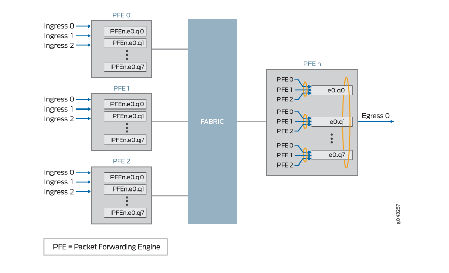
When congestion occurs because of the load on the egress output
queue, the ingress VOQs corresponding to the egress output queue contain
RED dropped packets.
Using the following procedure, you can identify the ingress
Packet Forward Engine (in terms of ingress traffic) that is contributing
to the egress congestion.
To determine which ingress Packet Forwarding Engine is contributing
to the RED dropped packets:
- Determine whether there are RED dropped packets on the
egress link.
Run the show interfaces queue interface-name command on the egress interface.
user@host> show interfaces queue et-7/0/0
In the show output, determine whether the interface
is experiencing RED dropped packets, by locating the RED-dropped packets
field and checking whether its value is greater than zero.
The following example shows RED-dropped statistics for the egress
Ethernet interface configured on port 0 of PIC 0, located on the FPC
in slot 7.
user@host> show interfaces queue et-7/0/0
Physical interface: et-7/0/0, Enabled, Physical link is Up
  Interface index: 206, SNMP ifIndex: 790
Forwarding classes: 16 supported, 8 in use
Egress queues: 8 supported, 8 in use
Queue: 0, Forwarding classes: fc0
  Queued:
    Packets              :             539433200              14896082 pps
    Bytes                :           38302319880            8461137824 bps
  Transmitted:
    Packets              :              67108815               1859497 pps
    Bytes                :            4294964160             952062464 bps
    Tail-dropped packets :                     0                     0 pps
    RL-dropped packets   :                     0                     0 pps
    RL-dropped bytes     :                     0                     0 bps
    RED-dropped packets  :             472324385              13036585 pps
    RED-dropped bytes    :           34007355720            7509075360 bps
Queue: 1, Forwarding classes: fc1
  Queued:
    Packets              :             539433555              14877096 pps
    Bytes                :           38302345472            8450201072 bps
  Transmitted:
    Packets              :              67108811               1859498 pps
    Bytes                :            4294963904             952062976 bps
    Tail-dropped packets :                     0                     0 pps
    RL-dropped packets   :                     0                     0 pps
    RL-dropped bytes     :                     0                     0 bps
    RED-dropped packets  :             472324744              13017598 pps
    RED-dropped bytes    :           34007381568            7498138096 bps
Queue: 2, Forwarding classes: fc2
  Queued:
    Packets              :             539433811              14892745 pps
    Bytes                :           38302363728            8459214984 bps
  Transmitted:
    Packets              :              67108833               1859501 pps
    Bytes                :            4294965312             952064512 bps
    Tail-dropped packets :                     0                     0 pps
    RL-dropped packets   :                     0                     0 pps
    RL-dropped bytes     :                     0                     0 bps
    RED-dropped packets  :             472324978              13033244 pps
    RED-dropped bytes    :           34007398416            7507150472 bps
Queue: 3, Forwarding classes: fc3
  Queued:
    Packets              :             539433461              14879323 pps
    Bytes                :           38302338584            8451484208 bps
  Transmitted:
    Packets              :              67108826               1859498 pps
    Bytes                :            4294964864             952062976 bps
    Tail-dropped packets :                     0                     0 pps
    RL-dropped packets   :                     0                     0 pps
    RL-dropped bytes     :                     0                     0 bps
    RED-dropped packets  :             472324635              13019825 pps
    RED-dropped bytes    :           34007373720            7499421232 bps
Queue: 4, Forwarding classes: fc4
  Queued:
    Packets              :             539433755              14884190 pps
    Bytes                :           38302359616            8454286816 bps
  Transmitted:
    Packets              :              67108843               1859508 pps
    Bytes                :            4294965952             952068096 bps
    Tail-dropped packets :                     0                     0 pps
    RL-dropped packets   :                     0                     0 pps
    RL-dropped bytes     :                     0                     0 bps
    RED-dropped packets  :             472324912              13024682 pps
    RED-dropped bytes    :           34007393664            7502218720 bps
Queue: 5, Forwarding classes: fc5
  Queued:
    Packets              :             539433849              14892950 pps
    Bytes                :           38302366384            8459333176 bps
  Transmitted:
    Packets              :              67108843               1859497 pps
    Bytes                :            4294965952             952062464 bps
    Tail-dropped packets :                     0                     0 pps
    RL-dropped packets   :                     0                     0 pps
    RL-dropped bytes     :                     0                     0 bps
    RED-dropped packets  :             472325006              13033453 pps
    RED-dropped bytes    :           34007400432            7507270712 bps
Queue: 6, Forwarding classes: fc6
  Queued:
    Packets              :             539434160              14879808 pps
    Bytes                :           38302388632            8451762856 bps
  Transmitted:
    Packets              :              67108861               1859514 pps
    Bytes                :            4294967104             952071168 bps
    Tail-dropped packets :                     0                     0 pps
    RL-dropped packets   :                     0                     0 pps
    RL-dropped bytes     :                     0                     0 bps
    RED-dropped packets  :             472325299              13020294 pps
    RED-dropped bytes    :           34007421528            7499691688 bps
Queue: 7, Forwarding classes: fc7
  Queued:
    Packets              :             539434364              14900946 pps
    Bytes                :           38302403328            8463940000 bps
  Transmitted:
    Packets              :              67108860               1859496 pps
    Bytes                :            4294967040             952061952 bps
    Tail-dropped packets :                     0                     0 pps
    RL-dropped packets   :                     0                     0 pps
    RL-dropped bytes     :                     0                     0 bps
    RED-dropped packets  :             472325504              13041450 pps
    RED-dropped bytes    :           34007436288            7511878048 bps
- If the interface is experiencing RED dropped packets,
run the
show interface voq interface-name command on the egress interface that is experiencing the RED
dropped packets.user@host> show interfaces voq et-7/0/0 non-zero
Tip: When using the show interfaces voq command,
you can use command filters to help locate the exact queue. For command
usage, see show interfaces voq.
- In the
show output, determine whether the interface
is experiencing RED dropped packets.The following example shows the count of the ingress RED-dropped
packets for the egress Ethernet interface configured on port 0 of
PIC 0, located on the FPC in slot 7.
The sample output shows that the cause of the congestion is
the ingress Packet Forwarding Engine PFE 0, on FPC number 4, and the
ingress Packet Forwarding Engine PFE 0 on FPC number 6, as denoted
by the count of RED-dropped packets.
user@host> show interfaces voq et-7/0/0 non-zero
Physical interface: et-7/0/0, Enabled, Physical link is Up
  Interface index: 156, SNMP ifIndex: 699

Queue: 0, Forwarding classes: q00

  FPC number: 4
    PFE: 0
      RED-dropped packets  :               6834995                 96929 pps
      RED-dropped bytes    :            5249276160             595537368 bps

  FPC number: 6
    PFE: 0
      RED-dropped packets  :               6835203                 96964 pps
      RED-dropped bytes    :            5249435904             595749256 bps

Queue: 1, Forwarding classes: q01

  FPC number: 4
    PFE: 0
      RED-dropped packets  :               6834998                 96967 pps
      RED-dropped bytes    :            5249278464             595766280 bps

  FPC number: 6
    PFE: 0
      RED-dropped packets  :               6835201                 96627 pps
      RED-dropped bytes    :            5249434368             593677664 bps

Queue: 2, Forwarding classes: q02

  FPC number: 4
    PFE: 0
      RED-dropped packets  :               6834997                 96921 pps
      RED-dropped bytes    :            5249277696             595482712 bps

  FPC number: 6
    PFE: 0
      RED-dropped packets  :               6835205                 96827 pps
      RED-dropped bytes    :            5249437440             594907344 bps

Queue: 3, Forwarding classes: q03

  FPC number: 4
    PFE: 0
      RED-dropped packets  :               6834997                 96961 pps
      RED-dropped bytes    :            5249277696             595731736 bps

  FPC number: 6
    PFE: 0
      RED-dropped packets  :               6835202                 96522 pps
      RED-dropped bytes    :            5249435136             593031808 bps

Queue: 4, Forwarding classes: q04

  FPC number: 4
    PFE: 0
      RED-dropped packets  :               6834995                 97021 pps
      RED-dropped bytes    :            5249276160             596099296 bps

  FPC number: 6
    PFE: 0
      RED-dropped packets  :               6835199                 96935 pps
      RED-dropped bytes    :            5249432832             595572304 bps

Queue: 5, Forwarding classes: q05

  FPC number: 4
    PFE: 0
      RED-dropped packets  :               6834996                 96949 pps
      RED-dropped bytes    :            5249276928             595656872 bps

  FPC number: 6
    PFE: 0
      RED-dropped packets  :               6835204                 96899 pps
      RED-dropped bytes    :            5249436672             595348960 bps

Queue: 6, Forwarding classes: q06

  FPC number: 4
    PFE: 0
      RED-dropped packets  :               6835000                 97019 pps
      RED-dropped bytes    :            5249280000             596088832 bps

  FPC number: 6
    PFE: 0
      RED-dropped packets  :               6835201                 96916 pps
      RED-dropped bytes    :            5249434368             595455624 bps

Queue: 7, Forwarding classes: q07

  FPC number: 4
    PFE: 0
      RED-dropped packets  :               6834999                 96929 pps
      RED-dropped bytes    :            5249279232             595536704 bps

  FPC number: 6
    PFE: 0
      RED-dropped packets  :               6835202                 96941 pps
      RED-dropped bytes    :            5249435136             595609968 bps
Note: For an aggregate interface, follow the same steps, but
you must run the show interface queue command on each
child link of the aggregate interface to determine which child egress
link is experiencing the congestion. Then run the show interface
voq command on that child link to determine which ingress Packet
Forward Engine is contributing to the congestion.